Advertisement
Table of Contents
- 1 Table of Contents
- 2 Getting Familiar with Your Welder - Read before Using
- 3 Getting Familiar with Your Gun
- 4 Creating a Proper Ground
- 5 Getting Ready to Weld
- 6 Welding Instructions
- 7 Identifying Common Issues
- 8 Welder Parts List
- 9 Welder Gun Parts List
- 10 Warranty Registration
- 11 Warranty
- Download this manual
Advertisement
Table of Contents

Related Manuals for Pro Spot AL-5


Summary of Contents for Pro Spot AL-5
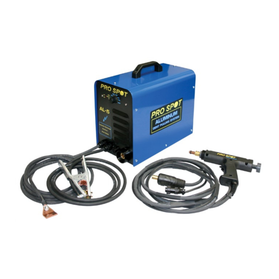
- Page 1 AL-5 Capacitor Discharge Aluminum Dent Pulling System Instruction Manual Version 1.02 Copyright © Pro Spot International, Inc. 2005-2011...
-
Page 2: Table Of Contents
GETTING FAMILIAR WITH YOUR WELDER - READ BEFORE USING GETTING FAMILIAR WITH YOUR GUN CREATING A PROPER GROUND GETTING READY TO WELD WELDING INSTRUCTIONS IDENTIFYING COMMON ISSUES WELDER PARTS LIST WELDER GUN PARTS LIST WARRANTY REGISTRATION WARRANTY Copyright © Pro Spot International, Inc. 2005-2011... -
Page 3: Getting Familiar With Your Welder - Read Before Using
(OH) Input Cable Ground Cable 1 Ground AL-5 Stud Gun Cable 2 Ground Cable 3 Positive Grounding Plate Cable 4 Input Cable Rear View Front Panel Zoom ON / OFF Switch Copyright © Pro Spot International, Inc. 2005-2011 Page 1... -
Page 4: Getting Familiar With Your Gun
AL-5 Getting Familiar with your Gun AL-5 Electrode Shaft Stud Electrode Adjustable Electrode Set Screws Pressure Knob Stud Trigger Switch Command Positive Cable Cable For Trigger Copyright © Pro Spot International, Inc. 2005-2011 Page 2... -
Page 5: Creating A Proper Ground
Creating A Proper Ground AL-5 Ground Plate Clean surface, weld a stud using the AL-5. Place the ground plate on top of the stud, use a wing nut or similar to tighten the plate to the panel. The closer the ground to the weld location, the better. -
Page 6: Getting Ready To Weld
Pressure Point Do Not Use The Arc melts the point Base of stud is fused to the panel Setting the Weld Voltage: Thickness: Set weld knob to: 60-90 70-110 80-130 Copyright © Pro Spot International, Inc. 2005-2011 Page 4... -
Page 7: Welding Instructions
Squeeze and hold trigger. Again, do not apply pressure to gun yet. With trigger still squeezed, apply downward pressure until the gun fires and the weld has been made. Copyright © Pro Spot International, Inc. 2005-2011 Page 5... -
Page 8: Identifying Common Issues
3. Point and head of stud touches the surface. BAD! 4. Head of stud touches the surface. BAD! 5. Electrode touches surface. BAD! Point. GOOD! No Point. BAD! 6. No point on stud. BAD! Will not work. Copyright © Pro Spot International, Inc. 2005-2011 Page 6... -
Page 9: Welder Parts List
NUT, BRASS N-96 FLANGE NUT 1/4-20 S-176 FHMS 8-32 X .75 S-38 PHMS 1/4-20 X .5 CLAMP, 76mm CAPACITOR 90-0155 COVER 80-5155 AL-5 COVER SIDE DECAL 51-0055 HANDLE 80-5154 FRONT PANEL DECAL Copyright © Pro Spot International, Inc. 2005-2011 Page 7... -
Page 10: Welder Gun Parts List
51-0314 SPRING M-108 1/4 X 1.0 DOWEL PIN 50-5501 TIP ASSY 52-2514 CABLE CLAMP 63-1357 PLUG WL-56 CABLE SHCS 1/4-20 X .625 80-5003 GUN DECAL ???? POSITIVE CABLE WL-05 TRIGGER CABLE Copyright © Pro Spot International, Inc. 2005-2011 Page 8... -
Page 11: Warranty Registration
AL-5 WARRANTY CARD Register Online: www.prospot.com 2625A Temple Heights Drive Oceanside CA 92056 USA FAX (760) 407-1421 PHONE (760) 407-1414... -
Page 12: Warranty
Pro Spot’s option of any part or parts, which may prove defective under intended use and service as determined by Pro Spot after said part or parts have been returned to and examined by Pro Spot whose address is 2625 Temple Hts. Drive ‘A’ ~ Oceanside, CA. - Page 13 Notes...
- Page 14 Notes...
- Page 15 Notes...
- Page 16 Pro Spot international, Inc. 2625 Temple Heights Dr Ste. A Oceanside, CA 92056 Toll Free: (877) PRO SPOT Phone: (760) 407-1414 Fax: (760) 407-1421 E-mail: info@prospot.com Web: www.prospot.com Copyright © Pro Spot International, Inc. 2005-2011...
Need help?
Do you have a question about the AL-5 and is the answer not in the manual?
Questions and answers