Table of Contents
Advertisement
Quick Links
Rev A
REF TEK 130-SMHR/9 Users Guide
This REF TEK manual provides startup and basic operating procedures for the 130-SMHR/9
Accelerograph (98060-00) using Command Line Firmware.
Reftek Systems Inc.
75 MacDonald Avenue, Unit 1
Dartmouth, Nova Scotia
B3B 1T8
Support Phone: 1-902-444-0539
Email: support@reftek.com
www.reftek.com
Reftek Systems Inc.
REF TEK 130-SMHR/9 Users Guide
98060-00-UG
98060-00-UG
Rev A
5/6/2021
5/6/2021
i
Advertisement
Table of Contents

Related Manuals for Reftek 130-SMHR/9


Summary of Contents for Reftek 130-SMHR/9
- Page 1 98060-00-UG REF TEK 130-SMHR/9 Users Guide 98060-00-UG Rev A 5/6/2021 This REF TEK manual provides startup and basic operating procedures for the 130-SMHR/9 Accelerograph (98060-00) using Command Line Firmware. Reftek Systems Inc. 75 MacDonald Avenue, Unit 1 Dartmouth, Nova Scotia...
- Page 2 Copyright© 2021 Reftek Systems Inc. All rights reserved. No part of this manual may be reproduced, copied or transmitted in any form outside the approved recipient’s organization without written permission from Reftek Systems Inc. Printed in CANADA Reftek Systems Inc.
- Page 3 Firmware Update: To update firmware from the FTP site 1. Login to our FTP site at: ftp.reftek.com/pub as: User name: Anonymous Password: Your E-mail address 2. Find the 130 firmware at ftp.reftek.com/pub/130/cpu/prom.
- Page 4 Rev A REF TEK 130-SMHR/9 Users Guide 5/6/2021 98060-00-UG Follow these steps to update the firmware of a 130 DAS: 1. Unzip the ‘main.s3’ file from the downloaded zip file of the most recently released firmware. 2. Copy the desired firmware image to the root of the Compact Flash as ‘main.s3’ using a PC with a Compact Flash reader or ftp into the 130 DAS, with a Compact Flash installed, in binary mode.
- Page 5 Rev A REF TEK 130-SMHR/9 Users Guide 5/6/2021 98060-00-UG Notation Conventions The following notation conventions are used throughout REF TEK documentation: Notation Description ASCII Indicates the entry conforms to the American Standard Code for Information Interchange definition of character (text) information.
- Page 6 Rev A REF TEK 130-SMHR/9 Users Guide 5/6/2021 98060-00-UG REF TEK Support and update notifications As a valued user of REF TEK equipment we would like to provide the best support possible. If you would like to know more about any of our REF TEK products and services, please visit our website at https://reftek.com/technical-support.
-
Page 7: Table Of Contents
General GPS operations ..........................26 Example configuration ..........................27 Formatting media ............................. 28 2.9.1 Clearing RAM on the 130-SMHR/9 ......................28 2.9.2 Formatting a disk in the 130-SMHR/9 ....................28 2.9.3 Checking status of a media device on 130-SMHR/9 ................29 Reftek Systems Inc. - Page 8 4.4.4 Delay Time/Speed ..........................44 5 130-SMHR/9 Assembly ................. 45 Introduction .............................. 45 Disassembly of the 130-SMHR/9 for service .................... 45 Assembly of the 130-SMHR/9........................46 130-SMHR/9 REF TEK IP67 Test ........................ 48 5.4.1 IP67 enclosure protection procedure ....................48 5.4.2...
- Page 9 Rev A REF TEK 130-SMHR/9 Users Guide 5/6/2021 98060-00-UG Introduction .............................. 55 Replacing the Compact Flash™ ......................... 55 RAM Backup Battery replacement ......................57 130-SMHR/9 cable list ..........................57 Connector Assembly & Maintenance ....................... 58 Warranty Statement ..........................60 Warranty/Non-Warranty Service ......................60 8 147A-01/3/INT/SM Triaxial Accelerometer Assembly ......
-
Page 11: 130-Smhr/9 Overview
This section describes connections and purpose of the REF TEK 130-SMHR/9. The 130-SMHR/9 (98060-00) unit is intended for deployment in buildings or other structures such as a bridge. This design, with an internal tri-axial accelerometer and external connectors for two external tri-axial accelerometers, is well suited for structural monitoring. -
Page 12: Specifications
Rev A REF TEK 130-SMHR/9 Users Guide 5/6/2021 98060-00-UG Specifications Mechanical Description Size 9.25” high x 8.0” long x 13.25” (235mm x 203mm x 336mm) Weight 10.5 lbs (4.8 kg) without internal battery Watertight Integrity IP67 Shock Survives 1 meter drop on any axis Operating Temperature -20°... - Page 13 Rev A REF TEK 130-SMHR/9 Users Guide 5/6/2021 98060-00-UG Calibration Enable User Command Type Step applied to feedback Communication Ethernet 10-Base-T: TCP/IP,UDP/IP,FTP,RTP Serial Asynchronous RS-232;1K,X-Modem,Y-Modem Serial Asynchronous RS-232;1K,X-Modem,Y-Modem Modem (optional) V.90 Recording Mode Trigger Type Continuous, External, Level, Vote Trigger...
-
Page 14: Purpose Of The 130-Smhr/9
3-point leveling. The standard accelerometer has a full scale range of +/- 4g. The 130-SMHR/9 is a rugged, portable, and versatile data recorder. The modular design of their hardware and software allows you to reconfigure the 130-SMHR/9 for various types of... -
Page 15: Recorder Connections
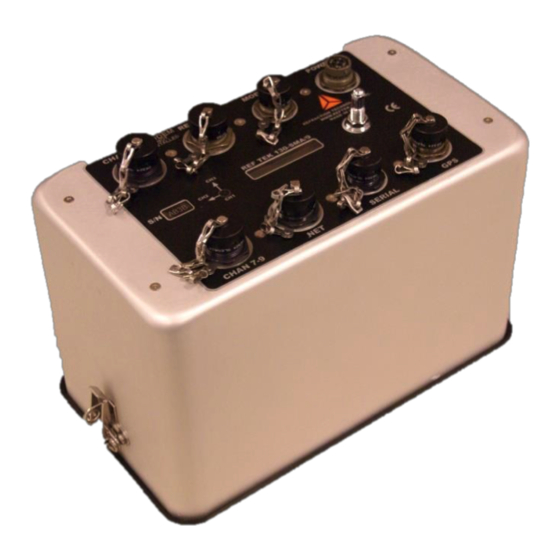
Rev A REF TEK 130-SMHR/9 Users Guide 5/6/2021 98060-00-UG Recorder Connections The functions of the standard connectors on the 130-SMHR/9 faceplate are as follows: Channels 4-6 Relays for External Optional Internal Power Connection Alarm Notification Modem (POTS) 130-GPS Channels 7-9... -
Page 16: Power Connector
98060-00-UG Power connector Power is supplied to the 130-SMHR/9 through one power connector. The hardware connection diagram on the previous page shows typical connections for the 130-SMHR/9. The following chart details individual connectors and REF TEK cable numbers. Recorder Connector and... -
Page 17: Gps Connector
130-SMHR/9 to an Ethernet port. Any IP addresses on one of the same subnets, as the 130-SMHR/9 unit, may connect using FTP and/or the command socket. However, the 130-SMHR/9 unit restricts the external IP addresses from which it will accept connections, to the equivalent of a Class C subnet containing the RTP host. - Page 18 Rev A REF TEK 130-SMHR/9 Users Guide 5/6/2021 98060-00-UG This connector also functions as the point of input for the external trigger. It also serves as the point of output for an event detection (trigger out) pulse. There is also a 12VDC nominal input on this connector to allow for lab setup via Ethernet using only this connector.
-
Page 19: Relay Connector
Rev A REF TEK 130-SMHR/9 Users Guide 5/6/2021 98060-00-UG Relay connector The relay connector on the 130-SMHR/9 provides three relay closures for certain software set able alarm conditions. Recorder Connector Pin Desc Electrical Desc Voltage Faceplate Range Relay PT0-7A-14-15P Relay 1 Normally Open Contact... -
Page 20: Channel 4-6 Connector
Rev A REF TEK 130-SMHR/9 Users Guide 5/6/2021 98060-00-UG Channel 4-6 connector The channel 4-6 connector on the 130-SMHR/9 provides inputs for an external sensor. Recorder Name Electrical Desc Voltage Range Note Faceplate Channel 4-6 CH4+ Channel 4 input + ±10 Volts... -
Page 21: Channel 7-9 Connector
Rev A REF TEK 130-SMHR/9 Users Guide 5/6/2021 98060-00-UG Channel 7-9 connector The channel 7-9 connector on the 130-SMHR/9 provides inputs for an external sensor. Recorder Name Electrical Desc Voltage Range Note Faceplate Channel 7-9 CH7+ Channel 7 input + ±10 Volts... -
Page 22: Hardware Modularity
Rev A REF TEK 130-SMHR/9 Users Guide 5/6/2021 98060-00-UG Hardware Modularity 130-SMHR/9 List of Hardware Four boards form the primary REF TEK 130-SMHR/9. The following table identifies each module. Board Description Purpose Lid Interconnect Board For 130-SMHR/9 (RT630-B01) Power Supplies Lightning Protection Internal V.90 Modem... -
Page 23: Frequently Asked Questions
ONLY then there is no effect, otherwise RAM will fill and acquisition will stop. For further clarification see the explanation in the section on the “Ethernet Port”. Question: What happens if the Compact Flash card is pulled from the 130-SMHR/9 when the LED is RED. - Page 24 Rev A REF TEK 130-SMHR/9 Users Guide 5/6/2021 98060-00-UG Question: Does the IBM Micro drive™ fit in the 130-SM Flash assembly? The IBM Micro drive™ does fit into the 130-SM but is unusable because the Micro drive is a rotating media and injects noise into the system that will affect the internal sensor (i.e.
-
Page 25: Operation With Command Line
Refer to the 130 Command Line Reference and 130 Command Line Theory of Operation for more information. The SMCC Users Guide also supplies useful information operation of the 130-SMHR/9. Reftek Systems Inc. -
Page 26: Establishing Minimal Hardware Connections
3. Provide a clear view of the sky for the GPS 4. Secure the appropriate cable from your control interface (PC) to your 130-SMHR/9 Serial port. 5. Secure the PT06A12-4S connector on your external power cable to the POWER connector on the recorder. -
Page 27: General Recorder Operation With Command Line
REF TEK pre-sets and tests the hardware of each 130-SMHR/9 before you receive the unit to ensure that it performs as specified. The 130-SMHR/9 does not require hardware adjustments for normal operations. You may use a 130-SMHR/9 as a stand-alone system, or you may use a Reftek Systems Inc. -
Page 28: Power Considerations
This section describes current draw, power load, and general power supply considerations for the 130-SMHR/9, peripherals, and subsystems. The 130-SMHR/9 operates on nominal 15-volt DC power (10 to 15 VDC). This range allows a 130- SMHR/9 to be powered from an ordinary lead acid battery that can be charged from either a solar or AC power source or through its internal battery charger. -
Page 29: Selectable Sensor Output Power
(between the 130-SMHR/9 and remote accelerometer) the output power should be changed on the 130-SMHR/9 to output +24 Volts power to the sensor. By supplying +24 Volts there can still be a high enough voltage to power the remote accelerometer even after the voltage drop due to the long cable run. - Page 30 Note: The accelerometer connection labels are on each cable and match the numbers on the RT570 board. Make sure the gasket stays in the base of the 130-SMHR/9 assembly. 7. Set the enclosure on a static free surface upside-down on its connectors.
-
Page 31: Port Settings And Modem Communications
To set up the configurations of the 130-SMHR/9 unit's ports, follow the instructions in the 130 Command Line Reference manual. Note: A 130-SMHR/9 is shipped pre-configured with a default IP address. Be sure to change this address before connecting the 130-SMHR/9 to an Ethernet port. -
Page 32: Command Port (Serial)
98060-00-UG Command Port (Serial) Each 130-SMHR/9 unit provides two bidirectional, asynchronous serial ports. The first of these ports is accessible at the Serial connector on the 130-SMHR/9 unit's faceplate. This port has the following primary functions and characteristics: Function Characteristics Primary Function Allows local command and control input through a serial connection to a terminal mode program. -
Page 33: Internal Modem Port
CAUTION: There will be only a loss of data while the acquisition state is off Internal modem port Each 130-SMHR/9 unit provides an optional internal modem, accessible at the Modem connector on the 130-SMHR/9 unit's faceplate. This port has the following primary functions and characteristics: Reftek Systems Inc. -
Page 34: To Remove The Internal Modem
130-SMHR/9 needs to be assembled. 4. Disconnect the cable from the RT570 board. Note: Make sure the seal strip stays on the enclosure lid of the 130-SMHR/9 assembly. 5. Place the dust caps on the unit and turn the enclosure lid on its connections. -
Page 35: Optional External Modem Port
98060-00-UG Modem 11. Cut the tie wrap on the modem module of the RT630 board located on the inside of the 130-SMHR/9 enclosure lid. 12. Remove the jumper (JP2) as shown in the figure below and remove the modem module from the RT630 board by gently pulling up the ends of the modem module (A slight rocking motion can be used if necessary). -
Page 36: General Gps Operations
2. Then into Push-to-fix mode (via serial commands), at which point the GPS will go to sleep. Note: The GPS is still powered from the 130-SMHR/9 but is drawing < 1 mA of power. The 130-SMHR/9 will stay asleep until reset by the 130-SMHR/9, or until it wakes up to check ephemeris data. -
Page 37: Example Configuration
4 Trigger votes level=50mG level=50mG 2 Detrigger votes 2 Detrigger votes level=30mG level=30mG 2. Save the file as trigger.prm 3. Put the file on the disk 4. Load the parameter file into the 130-SMHR/9 using the following command: {LP,0,\DSK1\trigger.prm Reftek Systems Inc. -
Page 38: Formatting Media
5/6/2021 98060-00-UG Formatting media The Media Format command can be used to clear the 130-SMHR/9 data RAM or to format a disk installed in the 130-SMHR/9. Clearing RAM on the 130-SMHR/9 1. To clear the 130-SMHR/9 data enter the following:... -
Page 39: Checking Status Of A Media Device On 130-Smhr/9
REF TEK 130-SMHR/9 Users Guide 5/6/2021 98060-00-UG Checking status of a media device on 130-SMHR/9 1. To check status of a device, based on the most recent MF command, on the 130-SMHR/9, enter the following: {MF,92CB,RQ Request status of the most recent MF command 2. -
Page 40: Sample Lcd Displays
Rev A REF TEK 130-SMHR/9 Users Guide 5/6/2021 98060-00-UG Sample LCD displays Display Initial power up LCD RAM Used out of Total Disk (Used out of Total) Date, Time and Temperature GPS status Position Power status of power to the 130 and battery backup power Acceptable Range: 10-15Volts Backup Range: 2.2-3.6 Volts... -
Page 41: 130-Smhr/9 Settings With Smcc
Port settings and modem communications DAS Control with SMCC Overview Communication with the 130-SMHR/9 occurs through a PC and the SMCC program or emulation program with command line. For further explanation of the SMCC program see the SMCC Users Guide. - Page 42 Rev A REF TEK 130-SMHR/9 Users Guide 5/6/2021 98060-00-UG Reftek Systems Inc.
- Page 43 5/6/2021 98060-00-UG The 130-SMHR/9 collects data based on the series of parameters that you select and implement. All 130-SMHR units have multiple datastream capability, allowing users a vast array of possible parameter combinations. You may set the following parameters for each datastream: •...
-
Page 44: Port Settings And Modem Communications
The 130-SMHR/9 does not require hardware adjustments for normal operations. You may use a 130-SMHR/9 as a stand-alone system, or you may use a network of many 130-SMHR/9 units deployed over a survey site. During field operations, the 130-SMHR/9 can store data in its own internal Compact Flash™... -
Page 45: Command Port (Serial)
98060-00-UG Command Port (Serial) Each 130-SMHR/9 unit provides two bidirectional, asynchronous serial ports. The first of these ports is accessible at the serial connector on the 130-SMHR/9 unit's faceplate. This port has the following primary functions and characteristics: Function Characteristics... -
Page 46: Toss Parameter
This port provides for connecting the optional internal modem to a phone line. Configuration By default, the 130-SMHR/9 software talks to the internal modem at 115,200 baud, no parity, 8 data bits, and 1 stop bit. Note: SMCC can be used to setup the modem port. The settings can be changed using the provided display. - Page 47 Rev A REF TEK 130-SMHR/9 Users Guide 5/6/2021 98060-00-UG This Page Left Intentionally Blank Reftek Systems Inc.
-
Page 49: Internal And 130-Modem Support
4 Internal and 130-Modem support Internal modem and the RT630 This section explains using a modem with the REF TEK 130-SMHR/9. A user should be familiar with whatever REF TEK host system is in current use. Documents for other REF TEK products are available on request. -
Page 50: Modem Features
(regardless of whether it is an internal or external modem). If the internal modem is used, or no modem is attached, the init string is not sent. 1. Enter the amount of time the 130-SMHR/9 waits, after turning on external power, before it tries to talk to the modem:... -
Page 51: Configure The Modem Initialization String
By doing this the external port can be used in a direct serial mode (presuming the internal modem is not installed). 1. To define the 130-SMHR/9 modem initialization parameters enter the following: Note: This is the Factory Default setting and is recommended when using the internal 130-MC modem. -
Page 52: Modem Dial Out Strings
There is also a second Dial string option in the 130-SMHR/9. Note: The 130-SMHR/9 will first call out using the first dial string Only if there is no answer at the first dial-string, the 130-SMHR/9 will call out using the second dial string. -
Page 53: Configure The Modem Initialization String
Rev A REF TEK 130-SMHR/9 Users Guide 5/6/2021 98060-00-UG Configure the modem initialization string The modem init string must have at least one AT command supplied. If the init and hang-up strings are null, then it is assumed that the modem port has no modem attached. By doing this the external port can be used in a direct serial mode (presuming the internal modem is not installed). -
Page 54: Modem Power Time Windows
Rev A REF TEK 130-SMHR/9 Users Guide 5/6/2021 98060-00-UG Modem Power Time Windows The Modem Power Time (Windows for external modem power) are used to define up to 10 different time windows (Start and duration) in which an external modem is supplied power. -
Page 55: 130-Smhr/9 Assembly
Note: The accelerometer connection labels are on each cable and match the numbers on the RT570 board. Make sure the gasket (Item 8) stays in the enclosure lid of the 130-SMHR/9 assembly. 5. If boards need to be removed place the unit on the connections that have the dust caps installed. -
Page 56: Assembly Of The 130-Smhr/9
7. Disconnect the CPU ribbon cables from the CPU board by spreading the ears on the connections of the CPU board. 8. At this point the individual boards may be gently lifted off the stack. 9. Refer to “Assembly of the 130-SMHR/9” to assemble the 130-SMHR/9. Number Description... - Page 57 Rev A REF TEK 130-SMHR/9 Users Guide 5/6/2021 98060-00-UG Note: If new replacement boards are added remember the SMI board is always last. 2. Insert the six removed #6-32 screws with the lock washers. 3. Tighten the board stack screws with a screwdriver.
-
Page 58: 130-Smhr/9 Ref Tek Ip67 Test
The 130-SMHR/9 meets the IP67 standard when properly sealed. In order to seal the unit for testing the following procedures need to be implemented. The REF TEK test is a simulation of the IP67 by removing air via the Prevent. -
Page 59: Pass Or Fail Vacuum Test Procedure
98060-00-UG Pass or Fail Vacuum Test procedure 1. Prepare the 130-SMHR/9 unit seal by lubricating the bottom and sides with an oil base lubricant. DC111 is recommended for this application, but petroleum jelly can be used. 2. Mate the lid to the base by aligning the lid’s seal with the base’s slot located on the perimeter of the base. - Page 60 Rev A REF TEK 130-SMHR/9 Users Guide 5/6/2021 98060-00-UG This Page Left Intentionally Blank Reftek Systems Inc.
-
Page 61: Permanent Field Installation
Assuming you have obtained or made up all the required cables, proceed to mount and level the 130-SMHR/9. The 130-SMHR/9 must be firmly mounted to a surface and leveled using the single pivot bolt and the three point leveling screws shown in the exploded 130-SMHR/9 view. -
Page 62: Disassemble The 130-Smhr/9 Case
6. Disconnect the ground cable from the base plate. Note: Make sure the gasket (Item 8) stays in the base of the 130-SMHR/9. 7. Secure the 130-SMHR/9 base plate to the platform location by placing over the installed Wedge Anchor (Item 16). -
Page 63: Re-Assemble The 130-Smhr/9
9. Install the 130-GPS with a clear view of the sky. 10. Secure the appropriate cable from your PC control interface to your 130-SMHR/9 Serial port of the recorder. 11. Secure the PT06A12-4S connector on your external power cable (130-8039) to the POWER connector on the recorder. - Page 64 Rev A REF TEK 130-SMHR/9 Users Guide 5/6/2021 98060-00-UG Number Description Assembly Cover Label, Lid Draw Latch #10-32x3/8 PPH #10-32 Seal Nuts #6-32x3/8 100 SEAL PFH #6-32x7/16 Standoff #Gasket Schrader Valve Cap, Dust Plastic Cap, Dust Shell #12 Cap, Dust Plastic...
-
Page 65: Periodic Maintenance Operations
Rev A REF TEK 130-SMHR/9 Users Guide 5/6/2021 98060-00-UG 7 Periodic Maintenance Operations Introduction The next two sections provide maintenance information for the 130-SMHR/9 on the following topics: • Replacing the Compact Flash™ • Connector Assembly & Maintenance • RAM Backup Battery replacement •... - Page 66 Loss of data on the drive The drive may have to be reformatted The 130-SMHR/9 recorder may have to be power-cycled 3. Grasp the Compact Flash™ from ONLY the sides. 4. Install a newly formatted drive in the slot and the LED, should turn GREEN.
-
Page 67: Ram Backup Battery Replacement
7. Snap and close the two draw latches. 130-SMHR/9 cable list Refer to the table below for the internal cable assemblies for the 130-SMHR/9 family Connection Internal Disk Interconnect cable CPU to Compact Flash Board... -
Page 68: Connector Assembly & Maintenance
Pin connections are supplied in the first section of the 130-SMHR/9 manual. When making the connections follow industry standard practices in dressing the cable end, soldering the connections and applying shrink tubing. - Page 69 3. The connectors have a machined groove inside. To avoid damaging this groove, you must apply a downward force while turning. Because connectors for the 130-SMHR/9 are constructed of an alloy, excessive force on the locking groove can cause burrs which make subsequent installation and removal of the connectors more difficult.
-
Page 70: Warranty Statement
Rev A REF TEK 130-SMHR/9 Users Guide 5/6/2021 98060-00-UG Warranty Statement REF TEK instruments are warranted free from defects of manufacture for one year from date of shipment. For the full text covering the Product Limited Warranty, Warranty Remedies, How to Obtain... -
Page 71: 147A-01/3/Int/Sm Triaxial Accelerometer Assembly
Rev A REF TEK 130-SMHR/9 Users Guide 5/6/2021 98060-00-UG 8 147A-01/3/INT/SM Triaxial Accelerometer Assembly Introduction This section describes the purpose of the REF TEK 147A-01/3/INT/SM Triaxial Accelerometer. Refer to the 147A-01/3/INT/SM Installation Guide for more information. Accelerometer Reftek Systems Inc. -
Page 72: Purpose Of The 147A-01/3/Int/Sm
Rev A REF TEK 130-SMHR/9 Users Guide 5/6/2021 98060-00-UG Purpose of the 147A-01/3/INT/SM The REF TEK tri-axial accelerometer assembly provides on-scale recording of earthquake motions at both near-fault locations and in a wide variety of building structure types. This accelerometer can be used in a variety of applications for measuring accelerations up to at least ±4.0g Full scale... -
Page 73: Logfile Example
Rev A REF TEK 130-SMHR/9 Users Guide 5/6/2021 98060-00-UG 9 Logfile example Timing examples 289:22:14:42 EXTERNAL CLOCK WAKEUP The DAS issues a command to turn on the power to the 130 GPS. 323:06:03:10 EXTERNAL CLOCK POWER IS TURNED ON The DAS gets a confirmation message from the 130-GPS that it has powered up. - Page 74 Rev A REF TEK 130-SMHR/9 Users Guide 5/6/2021 98060-00-UG 018:09:06:44 DSP CLOCK DIFFERENCE: 0 SECS AND -553 MSECS Indicates the difference, in milliseconds, between internal 1 Hz and 130-GPS 1 Hz before the DSP clock set or internal oscillator change.
- Page 75 Rev A REF TEK 130-SMHR/9 Users Guide 5/6/2021 98060-00-UG 018:09:06:45 DSP CLOCK HAS CHANGED 3 TIMES Indicates the DAS has made three changes to the internal clock since power up. 018:09:07:22 INTERNAL CLOCK PHASE ERROR OF -1 USECONDS The DAS internal clock or 1 Hz is compared to the 130-GPS 1 Hz periodically and the difference is noted. In this case: -1 µS...
-
Page 76: System Information
Rev A REF TEK 130-SMHR/9 Users Guide 5/6/2021 98060-00-UG System information 290:00:09:07 Using Ethernet RTP Link The DAS reports datastream parameters require data to be sent via Ethernet to an RTP host setup in the network parameters. 018:08:58:54 Serial Link K/T MODE: Keep STATE: Keep, LINE MODE: Direct Reporting Serial PPP parameters. - Page 77 Rev A REF TEK 130-SMHR/9 Users Guide 5/6/2021 98060-00-UG 018:08:58:54 Channel:Offset 4:$0001DF3A 5:$0001E00F 6:$0001DE49 Reports the DAS A/D offset in hex counts for channels 4 - 6. This offset is user selectable It is factory set for terminated input to center around zero counts. RT505 A/D inherent offset is approximately 123,000 decimal counts.
- Page 78 Rev A REF TEK 130-SMHR/9 Users Guide 5/6/2021 98060-00-UG 018:08:58:54 BATTERY VOLTAGE=12.775V, TEMPERATURE=4C, BACKUP= 03.346V Reports the status of battery voltages and temperature within the 130. Battery Voltage = External Supply Voltage Value Backup = Internal Backup Battery Voltage 323:06:03:11 POWERUP COMPLETE Indicates the DAS has booted correctly and reports it is now ready to acquire data now that basic system power checks are complete.
-
Page 79: Acquisition Information
Rev A REF TEK 130-SMHR/9 Users Guide 5/6/2021 98060-00-UG Acquisition Information 017:10:38:08 PARAMETERS ERASED Indicates the existing parameter set in the DAS has been erased. This is done before another parameter set is loaded. 017:10:38:08 PC1 Indicates the parameters for Channel 1 were received by the DAS. - Page 80 Rev A REF TEK 130-SMHR/9 Users Guide 5/6/2021 98060-00-UG 017:10:38:17 PK Indicates the parameters for Auto Center were received by the DAS. 017:10:38:16 PARAMETERS IMPLEMENTED Indicates that all new parameters were received by the DAS and have been loaded accordingly. For example gain relays for channels activated.
-
Page 81: Disk Access Information
Rev A REF TEK 130-SMHR/9 Users Guide 5/6/2021 98060-00-UG Disk Access Information 301:09:14:20 AUTO DUMP CALLED Indicates that RAM has reached the operator specified used amount and the DAS enables the RAM to Disk transfer. 357:10:55:02 IDE device: IBM-DSCM-11000 S/N: KHLZ9250 fw: SC2IC915 Specifies the disk device the RAM will be dumped to. - Page 82 Rev A REF TEK 130-SMHR/9 Users Guide 5/6/2021 98060-00-UG Reftek Systems Inc.
-
Page 83: Index
Rev A REF TEK 130-SMHR/9 Users Guide 5/6/2021 98060-00-UG 10 Index logfile examples ............... 61 A/D Converter ..............2 accelerometer - 147A ........... 3, 59 mating connectors ............. 1 assemble SMHR ............25, 45 media device status ............29 auxiliary channels ............... 2 media format.............. - Page 84 Rev A REF TEK 130-SMHR/9 Users Guide 5/6/2021 98060-00-UG relays and alerts ............33 trigger type supported ............. 17 station and channel parameters........32 status display ..............31 toss parameter ............. 35 triggers ................. 32 warranty ................58 specifications ..............2 RMA ................
- Page 85 Rev A REF TEK 130-SMHR/9 Users Guide 5/6/2021 98060-00-UG Reftek Systems Inc. 75 MacDonald Avenue, Unit 1 Dartmouth, Nova Scotia B3B 1T8 Support Phone: 1-902-444-0539 Email: support@reftek.com www.reftek.com Reftek Systems Inc.
Need help?
Do you have a question about the 130-SMHR/9 and is the answer not in the manual?
Questions and answers