Table of Contents
Advertisement
Quick Links
180-SMx2 Users Guide
180-SMx2-UG
Rev 1.0
11/29/2022
This REF TEK manual provides an overview and basic operating procedures for the SMA
2
(180-SMA)
and SMHR
2
(180-SMHR) and its related family of products.
Reftek Systems Inc.
75 MacDonald Avenue, Unit 1
Dartmouth, NS B3B 1T8
Canada
Tel: 1-902-444-0539
Email: support@reftek.com
www.reftek.com
Advertisement
Table of Contents

Subscribe to Our Youtube Channel
Related Manuals for Reftek 180-SM 2 Series


Summary of Contents for Reftek 180-SM 2 Series
- Page 1 11/29/2022 This REF TEK manual provides an overview and basic operating procedures for the SMA (180-SMA) and SMHR (180-SMHR) and its related family of products. Reftek Systems Inc. 75 MacDonald Avenue, Unit 1 Dartmouth, NS B3B 1T8 Canada Tel: 1-902-444-0539 Email: support@reftek.com...
- Page 2 Copyright© 2022 Reftek Systems Inc. All rights reserved. No part of this manual may be reproduced, copied or transmitted in any form outside the approved recipient’s organization without written permission from Reftek Systems Inc. Printed in CANADA Product warranty information For applicable product warranty information, please refer to the Warranty Card included with this product.
- Page 3 This alert warns of a potential hazard which, if not avoided, could result in WARNING severe injury or even death. This alert warns of a potential hazard or unsafe practice that could result in CAUTION minor injury or property damage or irretrievable data loss. NOTE: This is a note. Reftek Systems Inc.
- Page 4 On our support page, you can find information about submitting a support ticket, downloading sensor calibration sheets and exploring training options. You can contact us at: Support Email: support@reftek.com Support Phone: 1-902-444-0539 Thanks, Your REF TEK Support Team The latest version of REF TEK manuals can be found at https://manuals.reftek.com Reftek Systems Inc.
-
Page 5: Table Of Contents
4.1 Firmware Version .......................... 16 4.2 Update Firmware .......................... 16 5 Periodic Maintenance ....................17 5.1 Introduction ..........................17 5.2 Replacing the USB Disk ........................ 17 5.3 Replacing the RTC Battery ......................18 5.4 Replacing the Internal Main Battery ................... 18 Reftek Systems Inc. - Page 6 Rev 1.0 180-SMx2 Users Guide 11/29/2022 180-SMx2-UG 5.5 Connector Assembly and Maintenance ..................19 6 Recorder State of Health (Log) Messages ..............21 6.1 Keyword and Abbreviation Examples ..................21 6.2 Some Useful Message Examples ....................21 Reftek Systems Inc.
-
Page 7: Overview
NET: PT07A14-19P GPS: PT07A12-10S Power Input Voltage: Main power: 9.5 to 24 VDC Auxiliary battery: 11 to 20 VDC Average Power: 2.4W (3 channel, No Communications, No battery charging) 2.7W (3 channels, With Communications, No battery charging) Reftek Systems Inc. - Page 8 External pulse on trigger input line Recording Capacity RAM: 16 MB Internal non-volatile 8 GB SEEDlink ring buffer USB Flash Disk: 8/16/32/64 GB Recording Format: MRF Recording Format Format: MSD (miniSEED) Recording Format Compliance: Specifications: CE, FCC, RoHS Reftek Systems Inc.
-
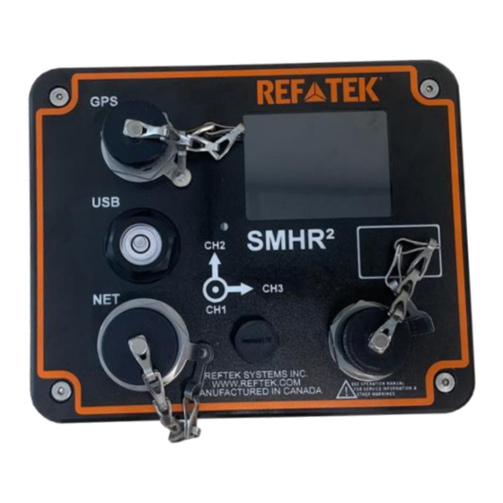
Page 9: Standard Faceplate Connections
NOTE: The internal battery, when installed, is only charged when Power A is above 14VDC. It is not charged from Pin B. An external battery on Pin B can also be charged when Power A is above 14VDC. Reftek Systems Inc. -
Page 10: Gps Connector: 10-Pin Pt07
The contents of the internal USB drive can be transferred to a computer using a USB-C to USB-A cable. The USB-C connector is in a sealed compartment underneath the bubble-level screw-cap. A USB-microAB port is also provided for factory diagnostic. Reftek Systems Inc. -
Page 11: Mating Connectors
DAS displays various status conditions using the color LCD display. In general, a green color indicates a positive working condition and a red color indicates a warning or error condition. The following table shows the various icons and their meaning. Reftek Systems Inc. - Page 12 Disk more than Wrap is USB% 99% total disabled USB used and Disk Wrap is enabled USB off and USB on USB off and a no data read read or write or write error errors occurred Reftek Systems Inc.
-
Page 13: General Recorder Control Considerations
• External trigger • Time Interval trigger • Time List trigger • Event trigger • Vote/External trigger Each trigger has its own set of parameters that determines the exact conditions under which the SMx DAS records data. Reftek Systems Inc. -
Page 14: Power Considerations
REF TEK if you require more accurate calculations or other information regarding power considerations. Solar power setups are frequently used in remote locations and these are available in several capacities that cover the various equipment configurations. Solar power arrays Reftek Systems Inc. -
Page 15: Sensor Control
NOTE: All channels of a datastream run at the same base sample rate. Question: Can I format the USB disk on the PC for use in the SMx recorder? For optimal performance in a REF TEK SMx recorder, USB disks should ALWAYS be formatted BY THE RECORDER. Reftek Systems Inc. -
Page 16: Warranty Statement
NOTE: It is advised to use a shipping company that can provide a tracking number. 3. Ship the unit to the this address, freight prepaid: Reftek Systems Inc. 75 MacDonald Avenue, Unit 1 Dartmouth, Nova Scotia B3B1T8... -
Page 17: Getting Started With Your Smx Das
7. Replace the screws in the 4 corners of the top. 8. Hold the magnet above the REF TEK triangle on the label until the LCD indicates the unit is shutting the unit down. Reftek Systems Inc. -
Page 18: Controlling Unit Power
184-GNSS power can be duty cycled. When the 184-GNSS is powered on, the DAS waits for time to become stable, and then phase locks its internal oscillator to the 184-GNSS pulse-per-second signal. Any drift and offset that was introduced while the 184-GNSS Reftek Systems Inc. -
Page 19: Ethernet For Configuration
5. On the mobile device, exit the Wi-Fi settings and open a web browser. 6. Enter the IP address of the DAS to display the configuration Web UI. 7. Check the status of the DAS using the Status tab and sub-menus. Reftek Systems Inc. -
Page 20: Setting Passwords
5. At the bottom of the screen, click Send. 6. Acquisition restarts immediately after sending the new datastream parameters. Acknowledge the alert. 7. Go back to the Monitor tab to see that only 1 channel is active. Reftek Systems Inc. -
Page 21: Installation
5. Adjust the leveling feet to level the unit, using the bubble level on the top of the unit. 6. Tighten each leveling foot as needed to secure each equally against the mounting surface. 7. Attach all cables to the unit. 8. Wave the magnet across the REF TEK triangle to power the unit up. Reftek Systems Inc. -
Page 22: Firmware Updates
DAS, you can alternatively hold the magnet to the DAS for 3 seconds to shut down the DAS, and then once the LEDs have all extinguished, hold the magnet for 1 second to start up the DAS again. Then wait for the ACQ LED to turn green. Reftek Systems Inc. -
Page 23: Periodic Maintenance
USB Disks not purchased from REF TEK may work at one temperature but not at another, or may work for some period of time and then fail all together. Reftek Systems Inc. -
Page 24: Replacing The Rtc Battery
10. Carefully replace the top of the unit back onto the base, making sure the edge connector of the Interface board attached to the bottom of the unit is properly inserted into its socket on the board stack inside the top. 11. Replace the screws in the 4 corners of the top. Reftek Systems Inc. -
Page 25: Connector Assembly And Maintenance
DAS units are constructed of an alloy, excessive force on the locking groove can cause burrs which make subsequent installation and removal of the connectors more difficult. 4. Do not attempt to remove a plug with pliers. Reftek Systems Inc. - Page 26 Rev 1.0 180-SMx2 Users Guide 11/29/2022 180-SMx2-UG 5. Assemble new connectors correctly as shown below. Reftek Systems Inc.
-
Page 27: Recorder State Of Health (Log) Messages
“CLOCK:PLL EXTERNAL POWER IS TURNED ON” This message is generated when the reference clock is powered on or activated. “CLOCK:PLL EXTERNAL POWER IS TURNED OFF” This message is generated when the reference clock is powered off or deactivated. Reftek Systems Inc. - Page 28 “CLOCK:PLL INTERNAL PHASE ERROR OF …” “CLOCK:PLL INTERNAL DRIFT OVER …” These messages are generated when a phase lock cycle is complete to indicate the observed phase and drift error present between the internal oscillator and the reference clock. Reftek Systems Inc.
Need help?
Do you have a question about the 180-SM 2 Series and is the answer not in the manual?
Questions and answers