Table of Contents
Advertisement
Quick Links
REF TEK 130-SMHR-C Users Guide
This REF TEK manual provides a basic overview of the 130-SMHR-C (97112-00) and its specifications when used
with Command Line Firmware.
Reftek Systems Inc.
75 MacDonald Avenue, Unit 1
Dartmouth, Nova Scotia
B3B 1T8
Support Phone: 1-902-444-0539
Email: support@reftel.com
www.reftek.com
96480-00-UG
Rev J
5/6/2021
Advertisement
Table of Contents

Subscribe to Our Youtube Channel
Related Manuals for Reftek 130-SMHR-C


Summary of Contents for Reftek 130-SMHR-C
- Page 1 REF TEK 130-SMHR-C Users Guide 96480-00-UG Rev J 5/6/2021 This REF TEK manual provides a basic overview of the 130-SMHR-C (97112-00) and its specifications when used with Command Line Firmware. Reftek Systems Inc. 75 MacDonald Avenue, Unit 1 Dartmouth, Nova Scotia...
- Page 2 Copyright© 2021 Reftek Systems Inc. All rights reserved. No part of this manual may be reproduced, copied or transmitted in any form outside the approved recipient’s organization without written permission from Reftek Systems Inc. Printed in CANADA Reftek Systems Inc.
- Page 3 Rev J REF TEK 130-SMHR-C Users Guide 5/6/2021 96480-00-UG REF TEK Support and update notifications As a valued user of REF TEK equipment we would like to provide the best support possible. If you would like to know more about any of our REF TEK products and services, please visit our website at https://reftek.com/technical-support.
- Page 4 Updating firmware in a 130-SMHR-C requires the presence of a firmware file on an installed Compact Flash device. 1. On power-up, the 130-SMHR-C checks the Compact Flash for the presence of ‘main.s3’ in the root directory. 2. If the ‘main.s3’ file is present on the Compact Flash, the 130-SMHR-C: Reads the file.
- Page 5 Compact Flash reader or ftp into the 130-SMHR-C, with a Compact Flash installed, in binary mode. 3. With the Compact Flash with the main.s3 image installed in the 130-SMHR-C, issue a reset command. (a) If you are at the 130-SMHR-C: 1.
- Page 6 Rev J REF TEK 130-SMHR-C Users Guide 5/6/2021 96480-00-UG Notation Conventions The following notation conventions are used throughout REF TEK documentation: Notation Description ASCII Indicates the entry conforms to the American Standard Code for Information Interchange definition of character (text) information.
-
Page 7: Table Of Contents
Optional Channel 4-6 connector ......................10 Hardware Modularity ..........................11 Frequently Asked Questions ........................12 2 Operation with Command Line ............. 13 Overview ..............................13 Getting started with your 130-SMHR-C ....................13 2.2.1 Establishing Minimal Hardware Connections ..................13 2.2.2 Basic setup steps: ........................... 15 DAS control overview .......................... - Page 8 96480-00-UG 2.16.2 Formatting a disk in the 130-SMHR-C ....................27 2.16.3 Checking status of a media device on 130-SMHR-C ................28 Sample LCD displays ..........................29 3 130-SMHR-C Settings with SMCC ............30 Overview ..............................30 DAS Control with SMCC Overview ......................30 Port settings and modem communications....................
- Page 9 Rev J REF TEK 130-SMHR-C Users Guide 5/6/2021 96480-00-UG 7 Periodic Maintenance Operations ............51 Introduction .............................. 51 Replacing the Compact Flash™ ......................... 51 RAM Backup Battery replacement ......................52 Installing an (Optional) Internal Battery ....................53 Connector Assembly & Maintenance ....................... 55 Warranty Statement ..........................
- Page 10 Rev J REF TEK 130-SMHR-C Users Guide 5/6/2021 96480-00-UG This Page Left Intentionally Blank Reftek Systems Inc.
-
Page 11: Smhr-C Overview
96480-00-UG 1 SMHR-C Overview Introduction This section describes operations and maintenance requirements for the REF TEK 130-SMHR-C. The 130-SMHR-C unit meets the USGS Advanced National Seismic System (ANSS) specifications for strong motion reference stations for deployment in urban areas. ANSS specification... -
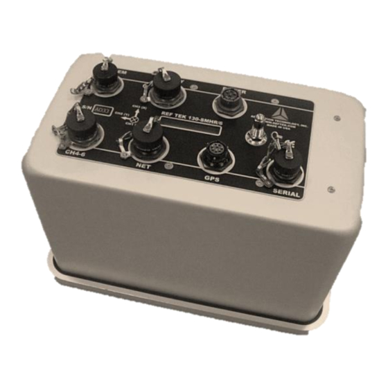
Page 12: Mating Connectors
Rev J REF TEK 130-SMHR-C Users Guide 5/6/2021 96480-00-UG Mating Connectors Function Mating Connector Serial PT06SE12-10S Power PT06A12-4P PT06SE12-8P PT06SE14-19S Channel PT06SE14-19P Modem PT06A12-3S Relay PT06SE14-15S 130-SMHR-C Specifications Mechanical Description Size 9.25” high x 8.0” long x 13.25” (235mm x 203mm x 336mm) Weight 10.5 lbs (4.8 kg) without internal battery... -
Page 13: Purpose Of The 130-Smhr-C
3-point leveling. The standard accelerometer has a full scale range of > ±4.0g. The 130-SMHR-C is a rugged, portable, and versatile data recorder. The modular design of their hardware and software allows you to reconfigure the 130-SMHR-C for various types of... -
Page 14: Recorder Connections
RT649 –B06 A/D for Ch 4-6 RT506-B01 CPU RT570-B01 Flash 147A-01/3/INT/SM Accelerometer Recorder Connections The functions of the standard connectors on the 130-SMHR-C faceplate are as follows: Relays for External 15V Power Internal Modem Optional Internal Alarm Notification 12V Battery... - Page 15 Rev J REF TEK 130-SMHR-C Users Guide 5/6/2021 96480-00-UG Reftek Systems Inc.
-
Page 16: Power Connector
Power connector Power is supplied to the 130-SMHR-C through one power connector. The hardware connection diagram on the previous page shows typical connections for the 130-SMHR-C. The following chart details individual connectors and REF TEK cable numbers. Recorder Connector and... -
Page 17: Gps Connector
0-3.3 Volts IRIGE 5 Volts Output1 0-5 Volts Modem connector The modem connector provides connections for the 130-SMHR-C internal modem. The modem connector is provided in order to connect the internal modem to the Plain-Old-Telephone- Service. Recorder Connector Pin Desc... -
Page 18: 130-Smhr-C Net Connector
130-SMHR-C to an Ethernet port. Any IP addresses on one of the same subnets, as the 130-SMHR-C unit, may connect using FTP and/or the command socket. However, the 130-SMHR-C unit restricts the external IP addresses from which it will accept connections, to the equivalent of a Class C subnet containing the RTP host. -
Page 19: Relay Connector
Rev J REF TEK 130-SMHR-C Users Guide 5/6/2021 96480-00-UG Relay connector The relay connector on the 130-SMHR-C provides three relay closures for certain software set able alarm conditions. Recorder Connector Electrical Desc Voltage Range Faceplate Desc Relay PT0-7A-14-15P Relay 1 Normally Open Contact... -
Page 20: Optional Channel 4-6 Connector
96480-00-UG Optional Channel 4-6 connector The optional channel 4-6 connector on the 130-SMHR-C provides inputs for an external sensor in place of the internal accelerometer. The internal A/D card must be re-configured in order to work with an optional external sensor. It is also optional to add another A/D card to use all six channels. -
Page 21: Hardware Modularity
Rev J REF TEK 130-SMHR-C Users Guide 5/6/2021 96480-00-UG Hardware Modularity 130-SMHR-C List of Hardware Four boards form the primary REF TEK 130-SMHR-C. The following table identifies each module. Board Description Purpose Lid Interconnect Board For 130-SMHR-C (RT530-B02) Power Supplies... -
Page 22: Frequently Asked Questions
Question: Does the IBM Microdrive™ fit in the 130-SMHR-C Flash assembly? The IBM Micro drive™ does fit into the 130-SMHR-C but is unusable because the Micro drive is a rotating media and injects noise into the system that will affect the internal sensor (i.e. Every time the Micro drive spins up, the rotational torque is transmitted through the case and measured by the sensor). -
Page 23: Operation With Command Line
5/6/2021 96480-00-UG 2 Operation with Command Line Overview This section provides information on the following topics: • Getting started with the 130-SMHR-C and quick power up. • Minimum hardware configuration. • General operation with command line control. • DAS control with the command line. - Page 24 Rev J REF TEK 130-SMHR-C Users Guide 5/6/2021 96480-00-UG • A cable to connect the control interface to the recorder. • One cable to connect the power supply to the recorder. Reftek Systems Inc.
-
Page 25: Basic Setup Steps
3. Provide a clear view of the sky for the GPS 4. Secure the appropriate cable from your control interface (PC) to your 130-SMHR-C Serial port. 5. Secure the PT06A12-4S connector on your external power cable to the POWER connector on the recorder. -
Page 26: General Recorder Operation With Command Line
The 130-SMHR-C does not require hardware adjustments for normal operations. You may use a 130-SMHR-C as a stand-alone system, or you may use a network of many 130-SMHR-C units deployed over a survey site. During field operations, the 130-SMHR-C can store data in its own internal Compact Flash™... -
Page 27: Power Considerations
130-SMHR-C, peripherals, and subsystems. The 130-SMHR-C operates on nominal 15-volt DC power (10 to 15 VDC). This range allows a 130- SMHR-C to be powered from an ordinary lead acid battery that can be charged from either a solar or AC power source or through its internal battery charger. -
Page 28: Battery Charger
The first operating mode is the normal float charge mode. In this mode the charging voltage will be approximately 13.7 Volts. The 130-SMHR-C will be in this mode when the current draw of the batteries is less than 500 mA. -
Page 29: Command Port (Serial)
5/6/2021 96480-00-UG Note: A 130-SMHR-C is shipped pre-configured with a default IP address. Be sure to change this address before connecting the 130-SMHR-C to an Ethernet port. Note: The 130-SMHR-C uses a 10BaseT Ethernet chip. The 130-SMHR-C Ethernet port may not work when connected to all 100BaseT and some 10/100BaseT Ethernet hubs. -
Page 30: Internal Modem Port
Primary Function This port provides for connecting the optional internal modem to a phone line. Configuration By default, the 130-SMHR-C software talks to the internal modem at 115,200 baud, no parity, 8 data bits, and 1 stop bit. Reftek Systems Inc. -
Page 31: To Remove The Internal Modem
5. Disconnect the 147A-01/3/ INT/SM Sensor Power cable and Sensor id cable from the RT570 board. Note: Make sure the gasket (Item 13) stays on the base of the 130-SMHR-C assembly. 6. Install the dust caps and set the 130-SMHR-C on its connections. - Page 32 Rev J REF TEK 130-SMHR-C Users Guide 5/6/2021 96480-00-UG 13. Remove the jumper (JP2) located on the RT530 board. 14. Remove the modem module from the RT530 board by gently pulling up the ends of the modem module (A slight rocking motion can be used if necessary).
-
Page 33: Re-Assemble The 130-Smhr-C
7. Connect the Sensor Power cable and Sensor ID cable to the RT570 board. Note: Make sure the gasket (Item 13) stays in the base of the 130-SMHR-C assembly. 8. Replace the enclosure lid setting it gently on the base lid avoiding contamination of the seal. - Page 34 Rev J REF TEK 130-SMHR-C Users Guide 5/6/2021 96480-00-UG Number Description Enclosure Lid Label, Lid Draw Latch #10-32x3/8 PPH #10-32 Seal Nuts #6-32x3/8 100 SEAL PFH #6-32x7/16 Standoff #Gasket Schrader Valve Cap, Dust Plastic Cap, Dust Shell #12 Cap, Dust Plastic...
-
Page 35: Optional External Modem Port
This port provides for connection to an external modem in lieu of the internal modem. Configuration By default, the 130-SMHR-C software sets it to 57,600 baud, no parity, 8 data bits, and 1 stop bit. The baud rate can be user configured. -
Page 36: Example Configuration
4 Trigger votes level=50mG level=50mG 2 Detrigger votes 2 Detrigger votes level=30mG level=30mG 2. Save the file as trigger.prm 3. Put the file on the disk 4. Load the parameter file into the 130-SMHR-C using the following command: {LP,0,\DSK1\trigger.prm Reftek Systems Inc. -
Page 37: Formatting Media
5/6/2021 96480-00-UG Formatting media The Media Format command can be used to clear the 130-SMHR-C data RAM or to format a disk installed in the 130-SMHR-C. Clearing RAM on the 130-SMHR-C 1. To clear the 130-SMHR-C data enter the following:... -
Page 38: Checking Status Of A Media Device On 130-Smhr-C
REF TEK 130-SMHR-C Users Guide 5/6/2021 96480-00-UG Checking status of a media device on 130-SMHR-C 1. To check status of a device, based on the most recent MF command, on the 130-SMHR-C, enter the following: {MF,92CB,RQ Request status of the most recent MF command 2. -
Page 39: Sample Lcd Displays
Rev J REF TEK 130-SMHR-C Users Guide 5/6/2021 96480-00-UG Sample LCD displays Display Initial power up LCD RAM Used out of Total Disk (Used out of Total) Date, Time and Temperature GPS status Position Power status of power to the 130 and battery backup power Acceptable Range: 10-15Volts Backup Range: 2.2-3.6 Volts... -
Page 40: 130-Smhr-C Settings With Smcc
Port settings and modem communications DAS Control with SMCC Overview Communication with the 130-SMHR-C occurs through a PC and the SMCC program or emulation program with command line. For further explanation of the SMCC program see the SMCC Users Guide. - Page 41 Rev J REF TEK 130-SMHR-C Users Guide 5/6/2021 96480-00-UG Reftek Systems Inc.
- Page 42 5/6/2021 96480-00-UG The 130-SMHR-C collects data based on the series of parameters that you select and implement. All 130-SMHR-C units have multiple datastream capability, allowing users a vast array of possible parameter combinations. You may set the following parameters for each datastream: •...
-
Page 43: Port Settings And Modem Communications
The 130-SMHR-C does not require hardware adjustments for normal operations. You may use a 130-SMHR-C as a stand-alone system, or you may use a network of many 130-SMHR-C units deployed over a survey site. During field operations, the 130-SMHR-C can store data in its own internal Compact Flash™... -
Page 44: Command Port (Serial)
96480-00-UG Command Port (Serial) Each 130-SMHR-C unit provides two bidirectional, asynchronous serial ports. The first of these ports is accessible at the serial connector on the 130-SMHR-C unit's faceplate. This port has the following primary functions and characteristics: Function Characteristics... -
Page 45: Toss Parameter
This port provides for connecting the optional internal modem to a phone line. Configuration By default, the 130-SMHR-C software talks to the internal modem at 115,200 baud, no parity, 8 data bits, and 1 stop bit. Note: SMCC can be used to setup the modem port. The settings can be changed using the provided display. - Page 46 Rev J REF TEK 130-SMHR-C Users Guide 5/6/2021 96480-00-UG This Page Left Intentionally Blank Reftek Systems Inc.
-
Page 47: Internal Modem
DSP data pump, a modem controller, on-chip RAM and ROM, an analog front end (AFE) a DAA, and analog output. Note: The 130-8279 modem cable is used with the 130-SMHR-C when supplied with an internal modem. Modem Connection This section provides general procedures for setting up and operating the REF TEK 130-SMHR-C with the internal SLM modem. -
Page 48: Modem Configuration
(regardless of whether it is an internal or external modem). If the internal modem is used, or no modem is attached, the init string is not sent. 1. Enter the amount of time the 130-SMHR-C waits, after turning on external power, before it tries to talk to the modem:... -
Page 49: Configure The Modem Initialization String
By doing this the external port can be used in a direct serial mode (presuming the internal modem is not installed). 1. To define the 130-SMHR-C modem initialization parameters enter the following: Note: This is the Factory Default setting and is recommended when using the internal 130-MC modem. -
Page 50: Modem Dial Out Strings
3. There is also a second Dial string option in the 130-SMHR-C. Note: The 130-SMHR-C will first call out using the first dial string. Only if there is no answer at the first dial-string, the 130-SMHR-C will call out using the second dial string. -
Page 51: Using Smcc For Modem Configuration
The SMCC command and control program is a multi-platform REF TEK program for command- line command and control of the 130-SMHR-C over a TCP/IP (LAN/WAN) connection through RTPD or through a serial connection. SMCC is a client-server application that serves up HTML pages to web browser clients. -
Page 52: Modem Power Time Windows
Rev J REF TEK 130-SMHR-C Users Guide 5/6/2021 96480-00-UG Modem Power Time Windows The Modem Power Time (Windows for external modem power) are used to define up to 10 different time windows (Start and duration) in which an external modem is supplied power. -
Page 53: 130-Smhr-C Assembly
Note: The accelerometer connection labels are on each cable and match the numbers on the RT570 board. Make sure the gasket (Item 8) stays in the base of the 130-SMHR-C assembly. Disconnect the (130-8371) Sensor Power cable and Sensor ID cable from RT570 board. -
Page 54: Assembly Of The 130-Smhr-C
8. Disconnect the CPU ribbon cables from the CPU board by spreading the ears on the connections of the CPU board. 9. At this point the individual boards may be gently lifted off the stack. 10. Refer to “Assembly of the 130-SMHR-C” to assemble the 130-SMHR-C. Number Description... -
Page 55: 130-Smhr-C Ref Tek Ip67 Test
A shut off is located in between the pump and the gauge. Pass or Fail Vacuum Test procedure 1. Prepare the 130-SMHR-C unit seal by lubricating the bottom and sides with an oil base lubricant. DC111 is recommended for this application, but petroleum jelly can be used. -
Page 56: Leak Test
1. Screw the plastic seal cap over the head of the mounting bolt. 2. Make sure that the O-ring is firmly compressed. 3. Prepare the 130-SMHR-C’s seal by lubricating the bottom and sides with an oil base lubricant. DC111 is recommended for this application, but petroleum jelly can be used. -
Page 57: Permanent Field Installation
Assuming you have obtained or made up all the required cables, proceed to mount, level and connect the GPS to the 130-SMHR-C. The 130-SMHR-C must be firmly mounted to a surface and leveled using the single pivot bolt and the three point leveling screws shown in the exploded 130-SMHR-C view. -
Page 58: Disassemble The 130-Smhr-C Case
Rev J REF TEK 130-SMHR-C Users Guide 5/6/2021 96480-00-UG 9. Unscrew the leveling screws (Item 14) three full turns. Remove the nut, washers, and spacer from the Wedge Anchor. Disassemble the 130-SMHR-C case 1. Power-off the 130-SMHR-C. 2. Flip the draw latches (Item 3). -
Page 59: Install Gps And Cables
2. Make sure the 130-GPS is in installed with a clear view of the sky. 3. Secure the appropriate cable from your PC control interface to your 130-SMHR-C Serial port of the recorder. 4. Secure the PT06A12-4S connector on your external power cable to the POWER connector on the recorder. -
Page 60: Final 147A-01/3 Adjustment
7. Push firmly on the top of the enclosure lid to ensure a complete seal. 8. Hook latches into the slot beneath the base plate. 9. Snap the two halves of the 130-SMHR-C together using the two draw latches (Item 3). Reftek Systems Inc. -
Page 61: Periodic Maintenance Operations
Rev J REF TEK 130-SMHR-C Users Guide 5/6/2021 96480-00-UG 7 Periodic Maintenance Operations Introduction The next two sections provide maintenance information for the 130-SMHR-C on the following topics: • Replace the Compact Flash™ • Connector Assembly & Maintenance • RAM Backup Battery replacement •... -
Page 62: Ram Backup Battery Replacement
• Loss of data on the drive • The drive may have to be reformatted • The 130-SMHR-C recorder may have to be power-cycled Green LEDs 4. Grasp the Compact Flash™ from ONLY the sides. 5. Install a newly formatted drive in the slot and the LED, should turn GREEN. -
Page 63: Installing An (Optional) Internal Battery
Rev J REF TEK 130-SMHR-C Users Guide 5/6/2021 96480-00-UG 4. Remove the enclosure lid (Item 1) and set it gently on the side of the base plate (not upside-down) to remove cables and avoid contamination of the seal Note: Be careful not to break the cables attached to the 147A-01/3/INT/SM Accelerometer and Compact Flash board. - Page 64 Rev J REF TEK 130-SMHR-C Users Guide 5/6/2021 96480-00-UG 4. Install the holding bracket with the screws provided in the kit. 5. Attach the internal battery cable from the RT530 board to the internal battery. 6. Re-position the enclosure top on the base plate matching the labels of orientation.
-
Page 65: Connector Assembly & Maintenance
Pin connections are supplied in the first section of the 130-SMHR-C manual. When making the connections follow industry standard practices in dressing the cable end, soldering the connections and applying shrink tubing. - Page 66 Rev J REF TEK 130-SMHR-C Users Guide 5/6/2021 96480-00-UG 4. Do not attempt to remove a plug with pliers. 5. Assemble new connectors correctly as shown below. Reftek Systems Inc.
-
Page 67: Warranty Statement
Rev J REF TEK 130-SMHR-C Users Guide 5/6/2021 96480-00-UG Warranty Statement REF TEK instruments are warranted free from defects of manufacture for one year from date of shipment. For the full text covering the Product Limited Warranty, Warranty Remedies, How to Obtain... -
Page 68: Logfile Example
Rev J REF TEK 130-SMHR-C Users Guide 5/6/2021 96480-00-UG 8 Logfile example Timing examples 289:22:14:42 EXTERNAL CLOCK WAKEUP The DAS issues a command to turn on the power to the 130 GPS. 323:06:03:10 EXTERNAL CLOCK POWER IS TURNED ON The DAS gets a confirmation message from the 130-GPS that it has powered up. - Page 69 Rev J REF TEK 130-SMHR-C Users Guide 5/6/2021 96480-00-UG 018:09:06:44 DSP CLOCK SET: OLD=04:018:09:06:44.553, NEW=04:018:09:06:44.000 The DAS internal clock change message that tells the operator: Time the internal clock was changed (DSP) Time the internal clock was at the time of the change Time it was changed to (The first change is always less than a second to line the internal 1 Hz to the 1 Hz of the 130-GPS.)
- Page 70 Rev J REF TEK 130-SMHR-C Users Guide 5/6/2021 96480-00-UG 018:09:06:45 INTERNAL CLOCK TIME SET During the first GPS power-on cycle the DAS waits 20 minutes, after initial LOCK, in case the GPS reports an additional 1 second shift due to a difference in its pages.
- Page 71 Rev J REF TEK 130-SMHR-C Users Guide 5/6/2021 96480-00-UG 305:02:37:56 SIRF: JERK The DAS compares the 130-GPS time to its internal oscillator time at the first GPS lock since 130 power-up or reset. If a change is required to equal the 130-GPS time, enables the timing algorithm that makes the change, Time Jerk. It gives the time it was enabled and will jerk the DAS internal clock with the next IPPS or 1 Hz rise from the 130-GPS.
-
Page 72: System Information
Rev J REF TEK 130-SMHR-C Users Guide 5/6/2021 96480-00-UG System information 290:00:09:07 Using Ethernet RTP Link The DAS reports datastream parameters require data to be sent via Ethernet to an RTP host setup in the network parameters. 018:08:58:54 Serial Link K/T MODE: Keep STATE: Keep, LINE MODE: Direct Reporting Serial PPP parameters. - Page 73 Rev J REF TEK 130-SMHR-C Users Guide 5/6/2021 96480-00-UG 018:08:58:54 Channel:Offset 1:$0001DE8A 2:$0001DFF7 3:$0001DDDD Reports the DAS A/D offset in hex counts for channels 1 - 3. This offset is user selectable. It is factory set for a terminated input to center around zero counts. RT505 A/D inherent offset is approximately 123,000 decimal counts.
- Page 74 Rev J REF TEK 130-SMHR-C Users Guide 5/6/2021 96480-00-UG 018:08:59:04 RTP: Stopped by event Open The DAS and the RTPD server use the TCP/IP stack to sync. If the connection is broken or a re-sync is initiated the DAS reports this message. It indicates the DAS and RTPD are negotiating a link or the DAS has lost its connection to RTPD and will attempt to re-sync.
-
Page 75: Acquisition Information
Rev J REF TEK 130-SMHR-C Users Guide 5/6/2021 96480-00-UG Acquisition Information 017:10:38:08 PARAMETERS ERASED Indicates the existing parameter set in the DAS has been erased. This is done before another parameter set is loaded. 017:10:38:08 PC1 Indicates the parameters for Channel 1 were received by the DAS. - Page 76 Rev J REF TEK 130-SMHR-C Users Guide 5/6/2021 96480-00-UG 017:10:38:16 PQ Indicates the parameters for calibration were received by the DAS. 017:10:38:17 PK Indicates the parameters for Auto Center were received by the DAS. 017:10:38:16 PARAMETERS IMPLEMENTED Indicates that all new parameters were received by the DAS and have been loaded accordingly. For example gain relays for channels activated.
-
Page 77: Disk Access Information
Rev J REF TEK 130-SMHR-C Users Guide 5/6/2021 96480-00-UG Disk Access Information 301:09:14:20 AUTO DUMP CALLED Indicates that RAM has reached the operator specified used amount and the DAS enables the RAM to Disk transfer. 357:10:55:02 IDE device: IBM-DSCM-11000 S/N: KHLZ9250 fw: SC2IC915 Specifies the disk device the RAM will be dumped to. -
Page 78: Index
Rev J REF TEK 130-SMHR-C Users Guide 5/6/2021 96480-00-UG 9 Index SLM2456 module ............35 SMCC configure ............39 modem connector .............. 7 accelerometer full-scale range ........... 3 NET connector ..............8 basic setup ................ 14 battery charger ................. 17 internal option .............. - Page 79 Rev J REF TEK 130-SMHR-C Users Guide 5/6/2021 96480-00-UG This Page Left Intentionally Blank Reftek Systems Inc.
- Page 80 Reftek Systems Inc. 75 MacDonald Avenue, Unit 1 Dartmouth, Nova Scotia B3B 1T8 Support Phone: 1-902-444-0539 Email: support@reftek.com www.reftek.com...
Need help?
Do you have a question about the 130-SMHR-C and is the answer not in the manual?
Questions and answers