Table of Contents
Advertisement
Quick Links
CS2RS Series RS485 Closed Loop Stepper Drive User Manual
User Manual
CS2RS Series
RS485 Closed Loop Stepper Drive
Revision 1.0
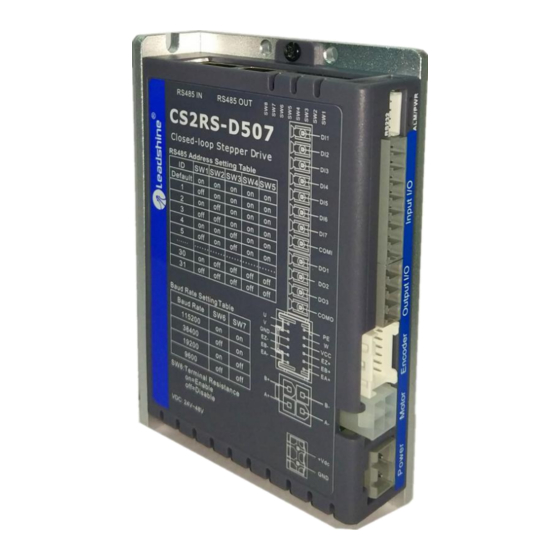
For Models of CS2RS-D503, CS2RS-D507, CS2RS-D1008
©2019 Leadshine Technology Co., Ltd.
Address: Floor 11, Block A3, Nanshan iPark, Xueyuan Avenue 1001, Shenzhen, Guangdong, 518055, China
Tel: (86)755-26409254
Fax: (86)755-26402718
Web:
www.leadshine.com
Sales:
sales@leadshine.com
Support:
tech@leadshine.com
1
Advertisement
Table of Contents
Troubleshooting

Subscribe to Our Youtube Channel
Related Manuals for Leadshine CS2RS Series


Summary of Contents for Leadshine CS2RS Series
- Page 1 CS2RS Series RS485 Closed Loop Stepper Drive User Manual User Manual CS2RS Series RS485 Closed Loop Stepper Drive Revision 1.0 For Models of CS2RS-D503, CS2RS-D507, CS2RS-D1008 ©2019 Leadshine Technology Co., Ltd. Address: Floor 11, Block A3, Nanshan iPark, Xueyuan Avenue 1001, Shenzhen, Guangdong, 518055, China...
- Page 2 Strictly adhere to the technical information regarding installation requirements. This manual is not for use or disclosure outside of Leadshine except under permission. All rights are reserved. No part of this manual shall be reproduced, stored in retrieval form, or transmitted by any means, electronic, mechanical, photocopying, recording, or otherwise without approval from Leadshine.
- Page 3 Preface Thank you for choosing CS2RS series RS485 closed loop stepper drive system of Leadshine Technology Co., Ltd. This manual gives required knowledge & precautions for using CS2RS series closed loop stepper drives. CS2RS Series are closed loop stepper drive based on standard Modbus RTU protocol, using RS485 communication can network up to 31 axes, built-in single axis control function with 16-segment position table (PR Mode).
-
Page 4: Table Of Contents
CS2RS Series RS485 Closed Loop Stepper Drive User Manual Contents 1 Introduction..............................1 1.1 Product Introduction..........................1 1.2 Features..............................1 1.3 Compare with Step/Direction.......................1 1.4 Check of Product..........................1 1.4.1 Arrival inspection........................1 1.4.2 Nameplate information......................2 1.4.3 Part number..........................2 1.4.4 Parts description........................3 1.4.5 Accessories Information......................3... - Page 5 CS2RS Series RS485 Closed Loop Stepper Drive User Manual 5 PR Functions..............................31 5.1 PR Main Features..........................32 5.2 Homing...............................33 5.2.1 Parameters..........................33 5.2.2. Homing by Origin Signal......................34 5.2.3. Homing by Limit Switch......................35 5.3 Position limit, JOG and E-stop function....................36 5.3.1 JOG............................38...
-
Page 6: Introduction
CS2RS Series also support the feature of teaching, the operation modes of Profile Position, Profile Velocity and Homing. They can power 2-phase NEMA 8, 11, 14, 17, 23, 24, 34 stepper motors with 1000 ppr to 5000 ppr incremental encoders. -
Page 7: Nameplate Information
CS2RS Series RS485 Closed Loop Stepper Drive User Manual Cheek if it is fully equipped with accessories. Accessories include power supply and I/O signals connector. CAUTION Neither the damaged nor missing accessories of stepper system is allowed to install. -
Page 8: Parts Description
CS2RS Series RS485 Closed Loop Stepper Drive User Manual 1.4.4 Parts Description 1.4.5 Accessories Information Name Necessary Picture Description (CABLEM-RZ*M*) for CS2RS-D503/507; Motor (CABLEH-RZ*M*) Motor Side: Drive Side: extension for CS2RS-D1008; Manufacturer: TE Manufacturer: Molex cable Optional length: Housing: 172159-1-4P Housing: 39012040 1.5m,3m,5m,8m,... -
Page 9: Installation
CS2RS Series RS485 Closed Loop Stepper Drive User Manual 2 Installation 2.1 Storage and Installation Conditions 2.1.1 Storage condition Correctly packaged and store in a clean and dry environment where direct sunlight is avoided. Store within an ambient temperature ranging from -20 to +65 ... -
Page 10: Installation Direction And Space
CS2RS Series RS485 Closed Loop Stepper Drive User Manual CS2RS-D1008 Figure 2.1: CS2RS Series Mechanical Drawing 2.3 Installation Direction and Space The mounting of drive, wiring and motor should be under the regulations of EN 61800-5-1. Incorrect installation may result in a drive malfunction or premature failure of the drive and /or motor. -
Page 11: Product Specifications
CS2RS Series RS485 Closed Loop Stepper Drive User Manual 3 Product Specifications CAUTION Don’t hot plug the motor wiring, encoder wiring and RS232 communication wiring during power on. Be sure to check the connections and make sure the power lead polarity is correct, ... -
Page 12: Wiring Instructions
CS2RS Series RS485 Closed Loop Stepper Drive User Manual 3.2 Wiring Instructions Figure 3.1 Wiring Instructions Note: (1) There are two RS485 communication ports above, one of them is input port which connects with master station or previous slave, and the other is output port which connects with the following slave. -
Page 13: Rs485 Communication Cable
CS2RS Series RS485 Closed Loop Stepper Drive User Manual 3.2.3 RS485 Communication Cable It is recommended to use shielded Ethernet network cables that do not exceed 100 meters. 3.3 Interface Specifications 3.3.1 Connectors Definition Figure 3.2: CS2RS series connectors Name... -
Page 14: Cn1 &Cn2 Input Power Connector For Cs2Rs-D503/507
CS2RS Series RS485 Closed Loop Stepper Drive User Manual 3.3.2 CN1 &CN2 Input Power Connector CS2RS-D503 / 507 Name Signal Description 24V- 48V Motor phase A+ Motor phase B+ Motor phase A- Motor phase B- CS2RS-D1008 Name Signal... -
Page 15: Cn4-I/O Signals Connector
CS2RS Series RS485 Closed Loop Stepper Drive User Manual 3.3.4 CN4-I/O Signals Connector Name Signal Description Configurable Single-ended Digital Inputs DI1-DI7, 12V - 24V. Compatible with common anode and common cathode wiring, max input frequency 10KHz, DI1 is enabling signal default,... -
Page 16: Cn6-Rs232 Tuning Port
3.3.6 CN6-RS232 Tuning Port Name Signal 3.3.7 DIP Switches The CS2RS series drives use an 8-bit DIP switched to set Slave ID (also called Site Alias), Baud Rate and Terminal Resistance, they are shown as below: Slave ID: SW1-SW5 (off=1, on=0) ... -
Page 17: I/O Connection
CS2RS Series RS485 Closed Loop Stepper Drive User Manual Note: “Default” means the parameter value can be set by Leadshine software or PLC software. “Factory” means the factory switch setting value Baud Rate: SW6 - SW7 Baud Rate 115200... -
Page 18: Digital Output
3.4.3 Brake Output Use PC software(from Leadshine or PLC vendor) to configure this output as a BRAKE CONTROL output. In this case, this signal can be used for automatic brake control while system power failure. This signal can be used for automatic brake control while system power failure. - Page 19 CS2RS Series RS485 Closed Loop Stepper Drive User Manual Figure 3.5: Brake output connection -14-...
-
Page 20: Modbus Rtu
CS2RS Series RS485 Closed Loop Stepper Drive User Manual 4 Modbus RTU 4.1 Communication Specifications Items Specifications Remarks Communication RS232 only for tuning RS485 and RS232 Port RS485 for motion control Baud Rate 9600/19200/38400/115200[bps] Parameter setting Synchronous Start / Stop Synchronization... -
Page 21: Function Codes
CS2RS Series RS485 Closed Loop Stepper Drive User Manual 4.2 Function Codes The current supported function codes as below 0x03: Read single or multiple data 0x06: Write single data 0x10: Write multiple data 4.2.1 FC= 0x01-- Read single or multiple bit... - Page 22 CS2RS Series RS485 Closed Loop Stepper Drive User Manual Slave->master data: Message: 00 0A 38 43 Number of bytes Description: Slave ID Value of 0x01 91 returned Note: 0x0191-- output peak current, 000A(Hexadecimal)=10(decimal, unit: 0.1A), it means the current 1A.
-
Page 23: 0X06-- Write Single Data
CS2RS Series RS485 Closed Loop Stepper Drive User Manual 4.2.4 FC= 0x06-- Write single address Sent Message (Master to Slave) Receive Message (Slave to Master) Slave ID 00 -- 1F Slaver ID 00 -- 1F High High Address write Address write... -
Page 24: 0X10-- Write Multiple Data
CS2RS Series RS485 Closed Loop Stepper Drive User Manual Note: 0x1801-- Auxiliary control word, and 0x2211 is to save the value to EEPROM. This step is required after the parameter has been modified, to prevent losing the written value after power-off. -
Page 25: Modbus Rtu Parameters
CS2RS Series RS485 Closed Loop Stepper Drive User Manual Message 01 46 00 04 00 00, 00 28, 00 00, 00 29 1C 14 First address Description Slave Number of Number Written value write address write of bytes Slave>master data:... - Page 26 CS2RS Series RS485 Closed Loop Stepper Drive User Manual closed loop motor vibration at this mode switching velocity point. Velocity switching 0x00A5 Pr2.02 point: closed loop to Usually keep the default value. 0-200 0.1RPS open loop Delay time of open 0x00A7 Pr2.03...
-
Page 27: Input And Output Function Configuration
CS2RS Series RS485 Closed Loop Stepper Drive User Manual 4: 8-bit data, no check,1 stop bit: 5: 8-bit data, no check,2 stop bits; 0x01C3 Pr5.25 RS485 control word 0-32767 0x01E1 Pr6.00 JOG speed 0-5000 r/min This JOG is triggered by RS485. - Page 28 SRV-ON 0x08 0x88 Clear error 0x07 0x87 4.3.3 PR Motion Parameters PR (Position Register) mode is developed by Leadshine, which supports uni-axis motion control function and can be configured with 16-segment position table. Register Par. # in Default Definition Range...
- Page 29 CS2RS Series RS485 Closed Loop Stepper Drive User Manual Origin signal The origin signal position on the coordinate system . Pr8.11 32767 0x600B position high bits Pr8.11 is high 16 bits, and Pr8.12 is low 16 bits Origin signal low Pr8.12...
- Page 30 CS2RS Series RS485 Closed Loop Stepper Drive User Manual =1---- interrupt(all the current ones are 1.); Bit5: OVLP, =0---- Non overlapping =1---- Overlapping Bit6: =0----absolute position =1----relative instructions Bit8-13: Jump to the corresponding PR path 0-15; bit14: JUMP, =0---- No jump...
-
Page 31: Status Monitoring Parameters
CS2RS Series RS485 Closed Loop Stepper Drive User Manual 4.3.5 Status Monitoring Parameters Register address Definition Attributes Unit Description 0x1001 Control Mode Invalid, always “0” Bit0: 0--normally, 1--faulty; Bit1: 0--drive disable, 1--enable; Bit2: 0--not running, 1--running; Bit4: 0-- Command not completed,... -
Page 32: Error Codes And Troubleshooting
CS2RS Series RS485 Closed Loop Stepper Drive User Manual 4.4 Error Codes and Troubleshooting 4.4.1 Communication Error Codes When the master station receive a message from the slave about a communication error, you can follow the table below for analysis Return Instructions (slave->master) -
Page 33: Alarm Information Parameter
CS2RS Series RS485 Closed Loop Stepper Drive User Manual Read Number of CRC check Description Slave ID Function code Register address registers code slave-> Master data: Message 81 60 Description Slave ID Function code+0x80 Error code CRC check code 4.4.2 Drive Alarm Codes and Troubleshooting... -
Page 34: Troubleshooting
CS2RS Series RS485 Closed Loop Stepper Drive User Manual working and red light will be flashed indicates the current error code. Whatever error occurs, the user need to power off the drive and restart it after removing the error. The user can read the corresponding error code through the PC software. The latest errors will be saved to EEPROM which supports 10 historical errors in the list. - Page 35 CS2RS Series RS485 Closed Loop Stepper Drive User Manual Clear history All history error records can be cleared by Leadshine History error error ProTuner -30-...
-
Page 36: Pr Functions
CS2RS Series RS485 Closed Loop Stepper Drive User Manual 5 PR Functions PR is uni-axial motion control function which is controlled by procedure software. Mainly uni-axial motion instructions control to, save the motion control function of the controller. Stepper Motion controller... -
Page 37: Pr Main Features
CS2RS Series RS485 Closed Loop Stepper Drive User Manual 5.1 PR Main Features PR (Position Register) mode is developed by Leadshine, which supports uni-axis motion control function and can be configured with 16-segment position table. Features Description The drive can detect homing signal by homing processing,and confirm the homing point of... -
Page 38: Homing
CS2RS Series RS485 Closed Loop Stepper Drive User Manual Note: 1) In PR control mode, the is 10000P/r and can not be modified 2) PR mode is valid when P0.01=0. Pulse/revolution 5.2 Homing Homing includes Homing by detecting limit signal , homing by detecting original signal set homing point by manual, auto homing after enabling drive. -
Page 39: Homing By Origin Signal
CS2RS Series RS485 Closed Loop Stepper Drive User Manual Note: Generally homing to find the origin signal, the motion is decelerating to stop, so after finding the origin will also move a distance, resulting in the actual read position value may not be 0, but in fact the position is accurate, and will output homing completion signal. -
Page 40: Homing By Limit Switch
CS2RS Series RS485 Closed Loop Stepper Drive User Manual (4) Origin Signal at Negative Direction 5.2.3. Homing by Limit Switch (1) Positive Limit Switch (2) Negative Limit Switch... -
Page 41: Position Limit, Jog And E-Stop Function
CS2RS Series RS485 Closed Loop Stepper Drive User Manual 5.3 Position limit, JOG and E-stop function Register Par. # in Default Definition Range Description address software Value Bit0: CTRG effective edge. 0--rising edge, 1--falling edge PR global control Bit1: Software limit.. - Page 42 CS2RS Series RS485 Closed Loop Stepper Drive User Manual Homing high Pr8.15 6000 The 1 segment speed of homing, unit: rpm 0x600F speed Pr8.16 Homing low speed 6000 The 2 segment speed of homing, unit: rpm 0x6010 Pr8.17 Homing Acc...
-
Page 43: Jog
CS2RS Series RS485 Closed Loop Stepper Drive User Manual 5.3.1 JOG JOG function JOG time sequence 5.3.2 Limit and E-stop Used for emergency stops E-stop time sequence... -
Page 44: Trigger Method
CS2RS Series RS485 Closed Loop Stepper Drive User Manual 5.4 Trigger Method Parameter Register address Definition Description Global Control function of PR: Bit0: CTRG =0: Rising edge trigger =1: Double edge trigger; Bit1: =0:Software limit is invalid =1: Software limit is valid;... -
Page 45: Immediately Trigger Method
CS2RS Series RS485 Closed Loop Stepper Drive User Manual Steps as below: 1. Firstly, configure required homing and path, it can be set through controller/PLC software after power-on , or through Leadshine PC software; 2. Enable drive; 3. Write corresponding command to the 0x6002 to realize the selection and startup of each action. -
Page 46: Trigger Path
CS2RS Series RS485 Closed Loop Stepper Drive User Manual Pr9.01 10-11 High position XXXX 12-13 Pr9.02 Low position XXXX 14-15 Pr9.03 Speed XXXX 16-17 Pr9.04 Acceleration XXXX Pr9.05 18-19 Deceleration XXXX 20-21 Pr9.06 Delay time XXXX 22-23 Pr9.07 Trigger control... -
Page 47: Timing Sequence
CS2RS Series RS485 Closed Loop Stepper Drive User Manual Pr9.02 0x6202 Position L Low 16 bit Pr9.03 0x6203 Speed Unit: rpm Pr9.04 0x6204 Unit: ms/1000rpm Pr9.05 0x6205 Unit: ms/1000rpm Pr9.06 0x6206 Suspend time Suspend time after the command is stopped Special PR Path 0 maps directly to Pr8.02, Others are... -
Page 48: Multi-Segment Jump
CS2RS Series RS485 Closed Loop Stepper Drive User Manual Single-end path sequence diagram 5.5.3 Multi-segment jump For example: set paths 5 and 9, set path 5 to jump to path 9. Multi-segment jump path sequence diagram 5.5.4 Continuous movement The bit5 of Pr9.00 is 0 , which does not overlap the continuous path. -
Page 49: Interrupt Function
CS2RS Series RS485 Closed Loop Stepper Drive User Manual Continuous movement timing sequence (no overlap). 5.5.5 Interrupt function The interrupt function is the priority of a PR path. Interrupts a valid path means that interrupting and abandoning the current path under trigger, and runs another path directly, which is similar as Interrupt priority of function.. As... -
Page 50: 8-Segment Pr Path, Which Can Be Selected By Combining
CS2RS Series RS485 Closed Loop Stepper Drive User Manual Set DI5 as trigger (CTRG) As shown in the table below, “on” means signal input on , “off “ means signal input off IO / PR path (ADD0) (ADD1) (ADD2) (ADD3) -
Page 51: 4-Segment Pr Path, Which Can Be Selected By Combining
CS2RS Series RS485 Closed Loop Stepper Drive User Manual 5.6.3 4-segment PR path, which can be selected by combining Set DI1 as path address 0 (ADD0), Set DI2 as path address 1 (ADD1), Set DI5 as trigger (CTRG). As shown in the table below, on means signal input on,off means signal input off...
Need help?
Do you have a question about the CS2RS Series and is the answer not in the manual?
Questions and answers