
Related Manuals for Leadshine EM542S


Summary of Contents for Leadshine EM542S
- Page 1 EM542S Digital Stepper Drive User Manual User Manual EM542S Digital Stepper Drive Revision 1.0 ©2017 All Rights Reserved ...
- Page 2 Leadshine assumes no responsibility for errors or omissions. Neither is any liability assumed for damages resulting from the use of the information contained herein. This document is proprietary information of Leadshine that is furnished for customer use ONLY. Information in this document is subject to change without notice and does not represent a commitment on the part of Leadshine. Therefore, information contained in this manual may be updated from time‐to‐time due to product improvements, etc., and may not conform in every respect to former issues. ...
-
Page 3: Table Of Contents
EM542S Digital Stepper Drive User Manual Table of Contents 1. Introduction ................................1 1.1 Features ................................1 1.2 Applications ................................. 1 2.1 Electrical Specifications ............................2 2.2 Environment ................................ 2 2.3 Mechanical Specifications ........................... 2 ... - Page 4 EM542S Digital Stepper Drive User Manual 11. Protection Functions ..............................12 12. Troubleshooting ............................... 13 13. Warranty .................................. 14 14. Contact Us ................................15 ...
-
Page 5: Introduction
(10-25%), quicker response time, control command smoothing, easy self-test, etc. The EM542S is able to power 2 phase (1.8°) and 4 phase (0.9°) stepper motors smoothly with very low motor heating & noise. It can take 20-50VDC supply voltage and output 1.0 to 4.2A current. All the micro step and output current configurations can be easily done via built in DIP switches. -
Page 6: Electrical Specifications
EM542S Digital Stepper Drive User Manual 2. Specifications 2.1 Electrical Specifications Parameters Typical Unit Output Current 4.2 (3.0 RMS) Supply Voltage 24 - 48 Logic signal current Pulse input frequency Minimal pulse width μS Minimal direction setup μS Isolation resistance MΩ... -
Page 7: Elimination Of Heat
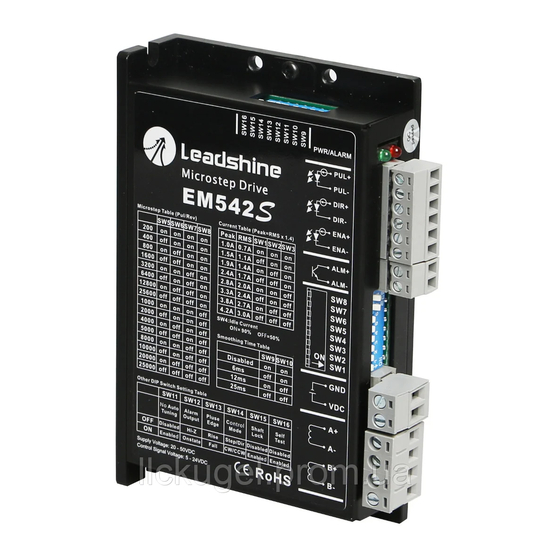
Figure 2 Connectors, DIP switches, and LED locations The EM542S has four terminal block connectors P1, P2, P3 & P4 (see above picture), and two DIP switch selectors S1 & S2. P1 is for control signal connections, P2 is for fault output, P3 is for power connection, and P4 is for motor connection. -
Page 8: P2 - Fault Output Connector
3.5 Status LED Lights There are two LED lights for EM542S. The GREEN one is the power indicator which should be always on in normal circumstance. The RED one is a drive status indication light, which will be OFF while working normally but ON and flash 1-2 times in a 3-second period in the case of enabled over-voltage or over-current protection. -
Page 9: Fault Output Connection
5.1 4-lead Motor Connection Refer to figure 7 for how to connect a 4-wire stepper motor. Configure EM542S output current to one of the 8 available values through DIP switches SW 1-3 of the DIP switch selector 1 (figure 2). -
Page 10: 6-Lead Motor Connection
Although setting the drive output current to 1.4 times of driven motor phase current will get the most torque, it is suggested to set an EM542S’s output current (peak of sinusoidal) to no more than 1.2 times the stepper motor’s phase current to prevent overheating. Refer to the next figure for how to connect an 8-lead stepper motor for parallel connection. -
Page 11: Power Supply Selection
PWM cycle, but not during the OFF duration. 6.2 Power Supply Sharing Multiple EM542S drives can share the same power supply, if that power supply has enough capacity. To avoid cross interference, connect each EM542S DIRECTLY to that shared power supply separately instead of connecting those power connectors of drives in daisy-chain connection. -
Page 12: Output Current Configuration (Sw1-3)
7.2 Idle Current Configuration (SW4) The SW4 of an EM542S is used to set output current percentage when motor is standstill. Idle current percentage will be set to 50% at OFF position, and 90% at ON position. When the driven stepper motor is idle (no movement) for 0.4... -
Page 13: Micro Step Configuration (Sw5-8)
EM542S will be automatically reduced to the configured percentage. 7.3 Micro Step Configuration (SW5-8) Each EM542S has 16 micro step settings which can be configured through DIP switch SW5, SW6, SW7, and SW8. See the following table for detail. Micro step Pulses/Rev. -
Page 14: Alarm Output Configuration (Sw12)
(SW14) DIP switch SW14 is used to configure the control mode of EM542S. By default it is set to OFF position for single pulse (step & direction, or pulse & direction) control. To change the control model to double pulse (CW/CCW) control type, set its position to OFF. -
Page 15: Typical Connection
EM542S Digital Stepper Drive User Manual 9. Typical Connection A complete stepping system should include stepping motor, stepping drive, power supply and controller (pulse generator). A typical connection is shown as figure 11. Figure 12 Typical connection 10. Sequence Chart of Control Signals... -
Page 16: Protection Functions
11. Protection Functions EM542S incorporates are built with over-voltage and over-current error protections. When it is under error protection, the red LED light will blink for one or two times in a period of 3 seconds. If fault output connection is connected, the impedance mode between ALM+ and ALM- will be changed (See “Fault Output Configuration”... -
Page 17: Troubleshooting
EM542S Digital Stepper Drive User Manual 12. Troubleshooting In the event that your drive doesn’t operate properly, the first step is to identify whether the problem is electrical or mechanical in nature. The next step is to isolate the system component that is causing the problem. As part of this process you may have to disconnect the individual components that make up your system and verify that they operate independently. -
Page 18: Warranty
Leadshine Technology Co., Ltd. warrants its products against defects in materials and workmanship for a period of 12 months from shipment out of factory. During the warranty period, Leadshine will either, at its option, repair or replace products which proved to be defective. -
Page 19: Contact Us
EM542S Digital Stepper Drive User Manual 14. Contact Us Leadshine Technology Co., Ltd Leadshine America Inc. (Headquarters) Address: Floor 11, Block A3, Nanshan iPark Address: 26050 Towne Centre Dr. 1001 Xueyuan Avenue Foothill Ranch, CA 92610 Nanshan District Shenzhen, Guangdong, 518055...
Need help?
Do you have a question about the EM542S and is the answer not in the manual?
Questions and answers