Table of Contents
Advertisement
CS-D1008 Closed Loop Stepper Drive User Manual
User Manual
CS-D1008
Closed Loop Stepper Drive
Revision 1.0
© 2016 Leadshine Technology Co., Ltd.
Address: Floor 11, Block A3, Nanshan iPark, Xueyuan Avenue 1001, Shenzhen, Guangdong, 518055, China
Tel: (86)755-26409254
Fax: (86)755-26402718
Web:
www.leadshine.com
Sales:
sales@leadshine.com
Support:
tech@leadshine.com
Advertisement
Table of Contents

Related Manuals for Leadshine CS-D1008


Summary of Contents for Leadshine CS-D1008
- Page 1 CS-D1008 Closed Loop Stepper Drive User Manual User Manual CS-D1008 Closed Loop Stepper Drive Revision 1.0 © 2016 Leadshine Technology Co., Ltd. Address: Floor 11, Block A3, Nanshan iPark, Xueyuan Avenue 1001, Shenzhen, Guangdong, 518055, China Tel: (86)755-26409254 Fax: (86)755-26402718 Web: www.leadshine.com...
- Page 2 Strictly adhere to the technical information regarding installation requirements. This manual is not for use or disclosure outside of Leadshine except under permission. All rights are reserved. No part of this manual shall be reproduced, stored in retrieval form, or transmitted by any means, electronic, mechanical, photocopying, recording, or otherwise without approval from Leadshine.
-
Page 3: Table Of Contents
9. Protection Functions ..............................9 10. Software Configuration ............................. 9 11. Accessories .................................. 9 12. Troubleshooting ................................. 9 13. Warranty .................................. 11 Appendix A. Leadshine CS-D1008 Compatible Stepper Motors ................12 Appendix B. Leadshine CS-D1008 Compatible Power Supplies ................13... -
Page 4: Introduction
CS-D1008 Closed Loop Stepper Drive User Manual 1. Introduction Leadshine CS-D1008 is a closed loop stepper drive designed to solve the loss of step problem in open loop stepper control systems, thus increase system reliability at minimal cost increase. It implements advanced control algorithm of Leadshine based on its tens of years’... -
Page 5: Environment
It is recommended to mount the drive vertically to maximize heat dissipation. Mount a cooling fan nearby if necessary. If multiple CS-D1008 drives are installed, it is suggested to keep a minimal 30mm (12 inches) between two of them. Page | 2... -
Page 6: Connections And Led Indication
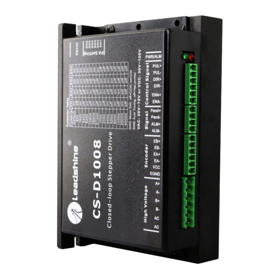
CS-D1008 Closed Loop Stepper Drive User Manual 3. Connections and LED Indication A CS-D1008 closed loop stepper drive has 5 connection blocks from P1 to P5 (see figure 2). Figure 2: CS-D1008 connectors 3.1 Connector P1 & P2– Control Input and Output Connections 3.1.1 Pin Assignments of P1 &... -
Page 7: Typical Control And Fault Output Connections
3.1.2 Typical Control and Fault Output Connections The CS-D1008 can accept differential and single-ended control signal inputs (open-collector and PNP output). A CS-D1008 has 3 optically isolated control inputs, PUL, DIR, and ENA. Refer to the following two figures for connections of open-collector and PNP signals. -
Page 8: Connector P4 - Motor And Power Supply Connection
3.5 LED Light Indication There are two LED lights for CS-D1008, one red and one green. The GREEN one is the power indicator which will be always on generally. The RED one is a protection indicator. It is off always when a CS-D1008 operates normally, but will flash 1, 2 or 7 times in a 5-second period when error protection is enabled. -
Page 9: Regulated Or Unregulated Power Supply
5.2 Power Supply Sharing Multiple CS-D1008 drives can share one power supply to save space and reduce cost, if that power supply has enough power capacity. To avoid cross interference, connect each stepper drive directly to the shared power supply separately. -
Page 10: Microstep Resolution (Sw1-Sw4)
CW (clockwise) CCW (counterclockwise) Auto Tuning 7. Typical Connection A complete closed loop stepper system should include a stepper motor with encoder, CS-D1008 drive, power supply and controller (pulse generator). A typical connection is illustrated in figure 6. Page | 7... -
Page 11: Sequence Chart Of Control Signals
CS-D1008 Closed Loop Stepper Drive User Manual Encoder Signal Controller CS-D1008 Connector PUL+ Encoder Encoder Step PUL- Extension Cable* Cable DIR+ *must be used Direction DIR- EA+: BLK EA-: BLU Power ENA+ EB+: YEL EB-: GRN Cable Enable +5V: RED GND: WHT... -
Page 12: Protection Functions
11. Accessories If you plan to use the ProTuner software, contact your supplier or Leadshine to purchase the RS232 cable with part number 1.4.4-0609505-B3 for connecting the CS-D1008 to a computer with Windows XP / 7 installed. In the case of... - Page 13 CS-D1008 Closed Loop Stepper Drive User Manual mechanical in nature. The next step is to isolate the system component that is causing the problem. As part of this process you may have to disconnect the individual components that make up your system and verify that they operate independently.
-
Page 14: Warranty
Leadshine Technology Co., Ltd. warrants its products against defects in materials and workmanship for a period of 12 months from shipment out of factory. During the warranty period, Leadshine will either, at its option, repair or replace products which proved to be defective. -
Page 15: Appendix A. Leadshine Cs-D1008 Compatible Stepper Motors
CS-D1008 Closed Loop Stepper Drive User Manual Appendix A. Leadshine CS-D1008 Compatible Stepper Motors The following Leadshine stepper motors with 1000-line encoders have been tested working with the CS-D1008 closed loop stepper drive. Frame Size Torque Length Model Series Notes (NEMA) (N.m / Oz-In) -
Page 16: Appendix B. Leadshine Cs-D1008 Compatible Power Supplies
CS-D1008 Closed Loop Stepper Drive User Manual Appendix B. Leadshine CS-D1008 Compatible Power Supplies It is highly suggested to use the following Leadshine power supplies to power CS-D1008 to get optimized performance. Those power supply are specially designed for stepper and servo controls.
Need help?
Do you have a question about the CS-D1008 and is the answer not in the manual?
Questions and answers