
Related Manuals for Leadshine EM Series


Summary of Contents for Leadshine EM Series
- Page 1 Hardware Installation Manual for EM Series Stepper Drives www.leadshine.com NTS-HWMN-EM-R2011101...
- Page 2 Leadshine reserves the right to make changes without further notice to any products herein to improve reliability, function or design. Leadshine does not assume any liability arising out of the application or use of any product or circuit described herein; neither does it convey any license under its patent rights of others.
- Page 3 Read this manual carefully before trying to install the stepper drive into your system. The person setup the stepper drive should have a better understanding on electronics and mechanics. Contact Leadshine technical guys when have questions on this document. Notice Make sure the power supply voltage dose not exceed the drive’s input range.
- Page 4 NTS-HWMN-EM-R20111018...
-
Page 5: Table Of Contents
Table of Contents 1. Family Overview ..............................1 Introduction ..............................1 .Product Covered .............................. 1 2-phase EM Stepper Drives ..........................1 3-phase EM Stepper Drives ................Fehler! Textmarke nicht definiert. Mechanical Specifications ..........................2 Elimination of Heat ............................3 3. Connectors and Pin Assignment ..........................3 4. - Page 6 Protection Indications ............................. 14 12. Frequently Asked Questions ..........................14 Problem Symptoms and Possible Causes ......................15 Appendix ................................16 Speed Torque Curves for Pre-Matching Leadshine Motors ................16 Twelve Month Limited Warranty ........................17 Exclusions ..............................17 Obtaining Warranty Service ..........................17 Warranty Limitations ............................
-
Page 7: Family Overview
They are capable of delivering high performance without damages to your machines or the materials. Leadshine EM series stepper drives are able to drive 2-phase stepper motors from NEMA8 to NEMA42. -
Page 8: Mechanical Specifications
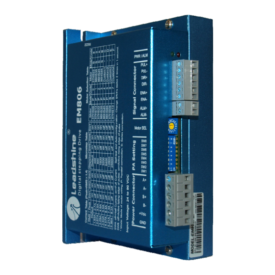
EM Series Drive Hardware Installation Manual Mechanical Specifications EM402 EM503 EM705 EM806 HWMN-EM-R20111018... -
Page 9: Elimination Of Heat
EM Series Drive Hardware Installation Manual Elimination of Heat Drive’s reliable working temperature(heat sink) should be <70 (158℉), and motor working temperature(surface) should be <80℃ (176℉); It is recommended to use automatic idle-current mode, namely current automatically reduce to 60% when motor stops, so as to reduce driver heating and motor heating;... -
Page 10: Control Signal Requirement
EM Series Drive Hardware Installation Manual 4. Control Signal Requirement Signal Mode and Sequence Chart Most EM drive can support Pulse/Direction and CW/CCW control signal modes. In order to avoid some fault operations and deviations, PUL, DIR and ENA should abide by some rules, shown as following diagram: Remark: ENA must be ahead of DIR by at least 5us. -
Page 11: Connecting Control Signal
EM Series Drive Hardware Installation Manual 5. Connecting Control Signal Most of the EM stepper drives can accept both differential and single-ended inputs (including open-collector and PNP output). Some only accept the single-ended inputs due to space limit NPN Signal Connections... -
Page 12: Connecting The Motor
EM Series Drive Hardware Installation Manual 6. Connecting the Motor The EM drive can drive any 2-pahse and 3-phase hybrid stepper motors. 2-phase, 4-lead Motors Connections 4 lead motors are the least flexible but easiest to wire. Speed and torque will depend on winding inductance. In setting the drive output current, multiply the specified phase current by 1.4 to determine the peak output current. -
Page 13: Phase, 8-Lead Motors Connections
EM Series Drive Hardware Installation Manual 2 phase, 8-lead Motors Connections 8 lead motors offer a high degree of flexibility to the system designer in that they may be connected in series or parallel, thus satisfying a wide range of applications. -
Page 14: Power Supply Selection
7. Power Supply Selection The DM drive can match medium and small size stepping motors (from NEMA frame size 8 to 34) made by Leadshine or other motor manufactures around the world. To achieve good driving performances, it is important to select supply voltage and output current properly. -
Page 15: Recommended Supply Voltage
EM Series Drive Hardware Installation Manual Recommended Supply Voltage The following table gives the recommended supply voltage for different drives. Model Voltage Range Typical Voltage Leadshine Power Supply DC(20-36)V DC 24V RPS2410(-L) EM402 DC(20-45)V DC 36V RPS369 EM503 EM705 DC(20-63)V... -
Page 16: Wiring Notes
EM Series Drive Hardware Installation Manual 9. Wiring Notes In order to improve anti-interference performance of the drive, it is recommended to use twisted pair shield cable. To prevent noise incurred in PUL/DIR signal, pulse/direction signal wires and motor wires should not be tied up together. It is better to separate them by at least 10 cm, otherwise the disturbing signals generated by motor will easily disturb pulse direction signals, causing motor position error, system instability and other failures. -
Page 17: Configuration Procedure
Active Edge Configuration Procedure If it is the first time installation and the EM drive works together with pre-matching Leadshine stepper motor, you can follow the steps below to configure the EM series stepper drive: Set the rotation switch according to the motor... -
Page 18: Auto Configuration
Auto Configuration If a non-Leadshine stepper motor is used in your system, switch SW3 (EM402) or SW4 (others) two times in one second to activate Auto-configuration for optimized performance if it is first time installation. Make sure the motor selection switch is set to one of the custom motor position. -
Page 19: Current Settings
When power supply voltage exceeds the limit, protection will be activated and red LED will blink twice within each periodic time. Sensorless Stall Detection By detecting motor voltage, current, and back-EMF signal, EM series drives can detect loss-of-synchronization of stepper motors without encoders. When the detection is activated, red LED will blink five times within each periodic time. -
Page 20: Protection Indications
EM Series Drive Hardware Installation Manual Note: When above protections are active, the motor shaft will be free or the LED will blink. Reset the drive by repowering it to make it function properly after removing above problems. For sensorless stall protection, you can also clear the error in ProTuner. See drive’s software operational manual for more information. -
Page 21: Problem Symptoms And Possible Causes
EM Series Drive Hardware Installation Manual Problem Symptoms and Possible Causes Symptoms Possible Problems No power Microstep resolution setting is wrong Motor is not rotating DIP switch current setting is wrong Fault condition exists The drive is disabled Motor rotates in the wrong direction... -
Page 22: Appendix
EM Series Drive Hardware Installation Manual Appendix Speed Torque Curves for Pre-Matching Leadshine Motors HWMN-EM-R20111018... -
Page 23: Twelve Month Limited Warranty
Leadshine Technology Co., Ltd. warrants its products against defects in materials and workmanship for a period of 12 months from shipment out of factory. During the warranty period, Leadshine will either, at its option, repair or replace products which proved to be defective.
Need help?
Do you have a question about the EM Series and is the answer not in the manual?
Questions and answers