Table of Contents
Advertisement
Quick Links
CS2RS Series
Modbus RS485 Stepper Drive
User Manual
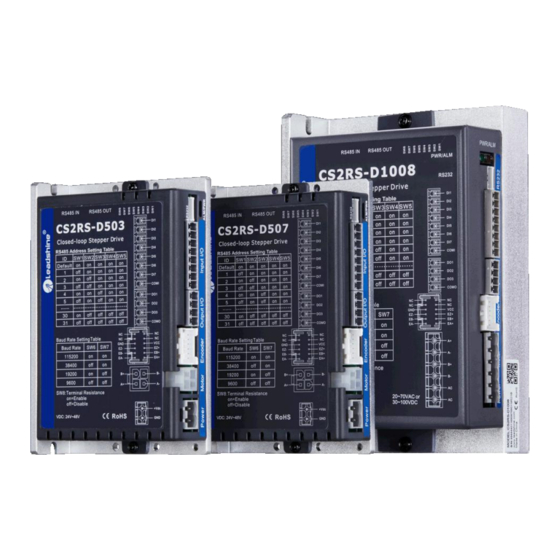
For Models of CS2RS-D503, CS2RS-D507 and CS2RS-D1008
©2019 Leadshine Technology Co., Ltd.
Address: 15-20/F, Block B, Nanshan I Valley, No.3185, Shahe West Road, Nanshan District,
Shenzhen, Guangdong, 518055, China
Tel: (86)755-26409254
Fax: (86)755-26402718
Web:
Sales:
www.leadshine.com
sales@leadshine.com
Support:
tech@leadshine.com
Advertisement
Table of Contents
Troubleshooting

Related Manuals for Leadshine CS2RS-D503


Summary of Contents for Leadshine CS2RS-D503
- Page 1 CS2RS Series Modbus RS485 Stepper Drive User Manual For Models of CS2RS-D503, CS2RS-D507 and CS2RS-D1008 ©2019 Leadshine Technology Co., Ltd. Address: 15-20/F, Block B, Nanshan I Valley, No.3185, Shahe West Road, Nanshan District, Shenzhen, Guangdong, 518055, China Tel: (86)755-26409254 Fax: (86)755-26402718...
- Page 2 Strictly adhere to the technical information regarding installation requirements. This manual is not for use or disclosure outside of Leadshine except under permission. All rights are reserved. No part of this manual shall be reproduced, stored in retrieval form, or transmitted by any means, electronic, mechanical, photocopying, recording, or otherwise without approval from Leadshine.
- Page 3 CS2RS Series Modbus RS485 Closed Loop Stepper Drive User Manual Safety Precautions Overall Notes Do not remove the housing with the drive powered on. Cables. Connectors and optional equipment. Please disconnect the power supply for at least 2 minutes and make sure the ...
- Page 4 CS2RS Series Modbus RS485 Closed Loop Stepper Drive User Manual Precautions for Installation Please install the drive in a cabinet that provides fire protection. Electrical protection in the control cabinet. Please install the driver and motor in a position with sufficient weight ...
-
Page 5: Table Of Contents
Table of Contents 1 Introduction.................................- 1 - 1.1 Product Introduction..........................- 1 - 1.2 Features..............................- 1 - 1.3 Application Scenarios..........................- 1 - 1.3.1 Hands-on Tuning..........................- 1 - 1.3.2 Practical Application Scenarios...................... - 2 - 1.4 Check of Product............................- 3 - 1.4.1 Arrival inspection..........................- 3 - 1.4.2 Nameplate information........................ - Page 6 4 Modbus RTU..............................- 15 - 4.1 Communication Specifications........................- 15 - 4.2 Modbus Function Codes (FC)......................... - 15 - 4.2.1 Read Holding Registers FC= 03....................- 16 - 4.2.2 Preset Single Register FC= 06......................- 17 - 4.2.3 Preset Multiple Registers FC= 10....................- 18 - 4.3 Modbus &...
- Page 7 6.1 Basic operation of Leadshine MotionStudio................... - 44 - 6.1.1 Preparation and Steps........................- 44 - 6.1.2 Operation of Trial Run........................- 46 - 6.1.3 Operation of PR Function......................- 47 - 6.2 Basic Operation of Serial Port Tools Software..................- 49 - 6.2.1 Preparation and Steps........................
-
Page 8: Introduction
Divided into simple hands-on tuning and practical application scenarios 1.3.1 Hands-on Tuning (1) The trial run can be performed with Leadshine's MS tuning software, which requires Leadshine’s tuning software, RS232 tuning cable (provided by Leadshine), RS232toUSB converter, drive and motor, as described in Section 6.1... -
Page 9: Practical Application Scenarios
CS2RS Series Modbus RS485 Closed Loop Stepper Drive User Manual 1.3.2 Practical Application Scenarios (1) Controlled by Modbus RS485 (PLC or HMI) The RS485 (Modbus-RTU protocol) communication triggers the drive's PR motion register, which can realize the drive's path motion. Both PLC and HMI have RS485 communication so user can choose one or both. -
Page 10: Check Of Product
Cheek if it is fully equipped with accessories. Accessories include power supply and I/O signals connector. Neither the damaged nor missing accessories of stepper system is allowed to install. Contact Leadshine or local distributor if any failure was found. 1.4.2 Nameplate information 1.4.3 Part number - 3 -... -
Page 11: Parts Description
CS2RS Series Modbus RS485 Closed Loop Stepper Drive User Manual 1.4.4 Parts description 1.4.5 Accessories Information Name Necessary Picture Description (CABLEM-RZ*M*) for CS2RS-D503/507; Motor (CABLEH-RZ*M*) Motor Side: Drive Side: extension for CS2RS-D1008; Manufacturer: TE Manufacturer: Molex cable Optional length: Housing: 172159-1-4P Housing: 39012040 1.5m,3m,5m,8m,... -
Page 12: Installation
DO NOT mount the drive and motor in a location subjected to airborne dust. Please ensure grounding wires are securely connected 2.2 Dimensions Unit: mm (1inch=25.4mm) CS2RS-D503 / 507 - 5 -... -
Page 13: Installation Direction And Space
CS2RS Series Modbus RS485 Closed Loop Stepper Drive User Manual CS2RS-D1008 Figure 2.1: CS2RS series mechanical drawing 2.3 Installation Direction and Space The mounting of drive, wiring and motor should be under the regulations of EN 61800-5-1. Incorrect installation may result in a drive malfunction or premature failure of the drive and /or motor. Please follow the ... -
Page 14: Product Specifications
Output Signals Brake, Alarm, In Position, GPIOs Protection Functions Over Current, Over Voltage, Position Following Error, Encoder Cable Error, etc. PC Software Leadshine ProTuner (coming soon) Environment Avoid dust, oil ,fog and corrosive gases Operating 0-50℃ (32 F – 122 F) -
Page 15: Wiring Instructions
CS2RS Series Modbus RS485 Closed Loop Stepper Drive User Manual 3.2 Wiring Instructions Figure 3.1 Wiring Instructions Note: (1) There are two RS485 communication ports one of them is input port which connects with master station or previous slave, and another is output port which connects with the following slave. (2) Single-ended inputs I1, I2, I3, I4, I5, I6 and I7 connection types can be common-cathode and common-anode. -
Page 16: Interface Specifications
RS485 communication connector RS232 tuning connector Encoder Signals Connector Salve ID: SW1-SW5 DIP Switch Baud Rate: SW6-SW7 Terminal Resistance: SW8 3.3.2 CN1 &CN2 Input Power Connector CS2RS-D503/507 Name Signal Description 24V- 48V Motor phase A+ Motor phase B+ Motor phase A-... -
Page 17: Cn3-I/O Signals Connector
Max. 24V/100mA, GPIOs. COMO Note:(1) DI or DO is shown as SI or SO in Leadshine MotionStudio. (2) DI1 is normally closed, default by Enable signal. It means the motor is locked shaft after the driver powered on. (3) When using brake output signals you need to connect a relay and a diode. -
Page 18: Cn5-Rs232 Tuning Port
CS2RS Series Modbus RS485 Closed Loop Stepper Drive User Manual RS485 RxD- 5, 6, 13, 14 7, 8, 15, 163, 4, 11, 12 Received Connector cover Shield GND 3.3.5 CN5-RS232 Tuning Port Name Signal 3.3.6 CN6-Encoder Input Signals Connector Name Signal Description 1, 2, 3, 4... - Page 19 CS2RS Series Modbus RS485 Closed Loop Stepper Drive User Manual (1) Slave ID: SW1-SW5 (off=1, on=0) Slave ID (default) (factory) Note: (1) When the SW1-SW5 is default (all are on), the Slave ID can be configured by the PC software - 12 -...
-
Page 20: I/O Connection
CS2RS Series Modbus RS485 Closed Loop Stepper Drive User Manual (2) Baud Rate: SW6 - SW7 Baud Rate 115200 (Default) 38400 (Factory) 19200 9600 Note: (1) When the SW6-SW7 is default (all are off), the Baud Rate can be configured by the PC software (3) Terminal Resistance Selection: SW8 SW8=ON: terminal resistance is valid;... -
Page 21: Brake Output
3.4.3 Brake Output Use PC software (from Leadshine or Controller or PLC vendor) to configure this output as a BRAKE CONTROL output. In this case, brake signal can be used for automatic brake control while system power failure. It is recommended to connect a fly- wheel diode in parallel to a 24VDC relay and brake coil connection. -
Page 22: Modbus Rtu
CS2RS Series Modbus RS485 Closed Loop Stepper Drive User Manual 4 Modbus RTU 4.1 Communication Specifications Items Specifications Remarks Communication RS232 only for fine tuning RS485 and RS232 Port RS485 for motion control Baud Rate 9600/19200/38400/115200[bps] Parameter setting Synchronous Start / Stop Synchronization Mode Communication Half-duplex, Master-slave Mode... -
Page 23: Read Holding Registers Fc
CS2RS Series Modbus RS485 Closed Loop Stepper Drive User Manual Function Type Description Code (FC) Read Holding Registers Requests content of holding registers Preset Single Register Writes to single holding register Preset Multiple Registers Writes to multiple holding register 4.2.1 Read Holding Registers FC= 03 Read Holding Registers Query (Master to Slave) Read Holding Registers Response (Slave to Master) Slave ID... -
Page 24: Preset Single Register Fc
CS2RS Series Modbus RS485 Closed Loop Stepper Drive User Manual Slave>master data: Message 00 00 00 02 00 00 00 01 00 00 00 04 Value Slave Number Value of Address Value of Value of Value of Description bytes returned 0x01BC 0x01BD 0x01BF... -
Page 25: Preset Multiple Registers Fc= 10
CS2RS Series Modbus RS485 Closed Loop Stepper Drive User Manual Example D: Save the written value to EEPROM Send message: 01 06 18 01 22 11 06 06 Receive message:01 06 18 01 22 11 06 06 Details as following: Master->slave data Message: 18 01... -
Page 26: Modbus & Pr Parameters
4.3.1 Basic Parameters Leadshine RS485 parameter data type is 32 bits, a parameter contains two registers of high 16 bits and low 16 bits, only the lower 16 bits are used in practice. However, when reading or writing multiple parameters in succession, the high 16 bits of the parameter need to be used as the start, usually 00. - Page 27 CS2RS Series Modbus RS485 Closed Loop Stepper Drive User Manual 0x21: Trigger homing; 0x014B Pr4.05 0-65535 SI4(input 4) 0x22: EMG (quick stop); 0x23: JOG+; 0x24: JOG-; 0x014D Pr4.06 0-65535 SI5(input 5) 0x25: POT (positive limit); 0x26: NOT (negative limit); 0x014F Pr4.07 0-65535 0x27: ORG (home switch);...
- Page 28 CS2RS Series Modbus RS485 Closed Loop Stepper Drive User Manual 0: 8-bit data, even check, 2 stop bits; 1: 8-bit data, odd check, 2 stop bits 2: 8-bit data, even check, 1 stop bit; 0x01C1 Pr5.24 RS485 data type selection 0-11 3: 8-bit data, odd check, 1 stop bit: 4: 8-bit data, no check,1 stop bit:...
-
Page 29: Input And Output Parameters
CS2RS Series Modbus RS485 Closed Loop Stepper Drive User Manual 4.3.2 Input and Output Parameters Register Par. # in Definition Description Range Default Unit Address software 0x0145 Pr4.02 SI1 (DI1) 0-65535 136 (0x88) (1) SI1 is set to enable by default, N.C 0x0147 Pr4.03 SI2 (DI2) - Page 30 The default state is 0000, which correspond to 10ms (2) If you need to set other filter times for the IO port, you can fill in the value manually in the parameter manage table of Leadshine MotionStudio. Example 1: IO input port 1 is set to enable function. Normally closed. Filter time 50ms The register value is configured as 0000 1100 1000 1000, which is converted to 3208 in decimal, i.e.
-
Page 31: Status Monitoring Parameters
CS2RS Series Modbus RS485 Closed Loop Stepper Drive User Manual Routine 3: IO input port 7 is set to JOG2 function. Normally open. Filter time 500ms The register configuration is 0000 1111 0010 1100, which is converted to 3884 in decimal, i.e. write 3884 to Pr4.08 to achieve the above configuration. -
Page 32: Error Codes And Troubleshooting
CS2RS Series Modbus RS485 Closed Loop Stepper Drive User Manual 4.4 Error Codes and Troubleshooting 4.4.1 Communication Error Codes When the master station receives a message from the slave about a communication error, you can follow the table below for analysis Return Commands (slave->master) Description... -
Page 33: Drive Alarm Codes And Troubleshooting
Shaft locking 0x80 1. Check whether the motor wire is broken error 1. Connect the drive to Leadshine software to 0x200 EEPROM error reset parameters to the factory 2. If it still exists, the hardware failure 1. Restart the drive;... -
Page 34: Register Mapping Continuous Read/Write Function
(2) There are two methods to clear the current alarm: one is via Clear current error Current error Leadshine MotionStudio, and the second is via external I/O, refer to Section 4.3.2. (3) If the current error cannot be cleared, please check the drive... -
Page 35: S-Code Application
CS2RS Series Modbus RS485 Closed Loop Stepper Drive User Manual 0x0F16 (Pr7.01: encoder resolution) ←--→ 0x0F17 (Pr7.09: over-voltage threshold) ←--→ 0x0F18 (Pr8.46: digital inputs) ←--→ 0x0F19 (Pr9.03: PR0 velocity) ←--→ Message Example Conditions: Drive ID is 1, motor is stationary. (1) Mapping Master→Slave: 01 10 0F 10 00 0A 00 00 01 00 09 00 A1 01 91 01 67 01 73 02 33 02 43 60 2E 62 03 4B 43... -
Page 36: Enable Drive
DI1 of CS2RS series drive is the enable input by default, normally closed, so CS2RS drive immediately enters the enable state after power on. RS485 communication: Pr0.07 of Leadshine MotionStudio (Register address 0x00F) set to value “1” indicates enable the drive by RS485 - 29 -... -
Page 37: Pr Mode (Indexer Table)
CS2RS Series Modbus RS485 Closed Loop Stepper Drive User Manual 5 PR Mode (Indexer Table) PR mode is a single-axis motion control function with 16-segment position table, also called indexer table. It can save the motion control function of the controller. 5.1 PR Main Features PR mode can mainly set the following functions: Features... -
Page 38: Homing Parameters
Trigger to homing: when IO port set to Home function triggered by external level, or trigger via Modbus RS485. Homing method: Limit switch homing: Set by register address 0x600A, or Leadshine software. If the homing direction is positive, then it is positive limit switch homing. Conversely, the negative limit homing. -
Page 39: Homing By Home Switch
CS2RS Series Modbus RS485 Closed Loop Stepper Drive User Manual Bit0: homing direction =0: CCW; =1: CW. Bit1: move to the Specified point after homing? =0: No; =1: Yes. Bit2- Bit3: homing method Pr8.10 0x600A Homing mode =00: Homing by detecting limit switch signal =01: Homing by detecting Home Switch signal =10: Homing by Z signal (index signal) Note:... - Page 40 CS2RS Series Modbus RS485 Closed Loop Stepper Drive User Manual (2) Home Switch at Positive Direction (3) Home Switch & Negative Limit Switch - 33 -...
-
Page 41: Homing By Limit Switch
CS2RS Series Modbus RS485 Closed Loop Stepper Drive User Manual (4) Home Switch at Negative Direction 5.2.3. Homing by Limit Switch (1) Positive Limit Switch (2) Negative Limit Switch - 34 -... -
Page 42: Soft Limit & Jog & Quick Stop
CS2RS Series Modbus RS485 Closed Loop Stepper Drive User Manual 5.3 Soft Limit & JOG & Quick Stop 5.3.1 Soft Limit The soft limit function means that the internal position feedback of the drive is compared with the limit position, an alarm and stop when determining that the motor exceeds the limit position. -
Page 43: Quick Stop
CS2RS Series Modbus RS485 Closed Loop Stepper Drive User Manual RS485 communication trigger JOG: Write value 0x4001 to 0x1801, JOG+. Write value 0x4002 to 0x1801, JOG-. JOG velocity: Pr6.00 (0x01E1). JOG acceleration and deceleration time: Pr6.03 (0x01E7). ... -
Page 44: Pr Path
5.4.1 PR Parameters Usually it is recommended using the PTP window of the Leadshine tuning software to configure the PR path parameters, but it can also use the following objects: Par. -
Page 45: Pr Path Configuration
CS2RS Series Modbus RS485 Closed Loop Stepper Drive User Manual paths paths Similar as above Similar as above Pr9.56- Pr9.63 PR path 7 paths paths Similar as above Similar as above Pr9.64- Pr9.71 PR path 8 paths paths 5.4.2 PR Path Configuration If use the digital input ports to configure the PR path, they can be set to ADD0, ADD1, ADD2 and ADD3, thus forming 16- segment PR path, and then trigger the path number to complete the PR motion. - Page 46 CS2RS Series Modbus RS485 Closed Loop Stepper Drive User Manual Single path sequence diagram 5.5.3 Multi-segment Jump For example: set paths 5 and 9, set path 5 to jump to path 9. Multi-segment jump path sequence diagram Continuous movement ...
-
Page 47: Trigger Methods
CS2RS Series Modbus RS485 Closed Loop Stepper Drive User Manual Continuous movement timing sequence (no overlap). Interrupt function The interrupt function is the priority of a PR path. Interrupts a valid path means that interrupting and abandoning the current path under trigger, and runs another path directly, which is similar as Interrupt priority of function.. -
Page 48: Io Combination Trigger
CS2RS Series Modbus RS485 Closed Loop Stepper Drive User Manual Register Par. # Definition Description address Global Control function of PR: Bit0: CTRG =0: Rising edge trigger =1: Double edge trigger; Bit1: Pr8.00 0x6000 PR control setting =0: Soft limit is invalid =1: Soft limit is valid;... -
Page 49: Fixed Trigger
Steps as below: 1. Firstly, configure required homing and path, it can be set through controller/PLC software after power-on , or through Leadshine PC software; 2. Enable drive; 3. Write corresponding command to the 0x6002 to realize the selection and startup of each action. - Page 50 CS2RS Series Modbus RS485 Closed Loop Stepper Drive User Manual The position & velocity& homing and so on are achieved through one data frame. This method uses PR0 to implement, which has 8 data, the last parameter Pr9.07 is mapped to Pr8.02, writing value 0x10 to it will trigger PR0 motion immediately, thus realizing the immediate trigger operation.
-
Page 51: Tuning Operations
CABLE-PC-1 Pin Definition It is recommended that users order this cable directly from Leadshine, not to make it yourself (2) USB to RS232 converter, sometimes it needs to manually install the drive program. (3) COM port selection, as shown in the figure below, the communication port is COM3: (4) Connect tuning software Select COM3, do not select baud rate and device number, keep the default settings. - Page 52 CS2RS Series Modbus RS485 Closed Loop Stepper Drive User Manual (5) Basic parameter setting (6) Input and output function and polarity setting - 45 -...
-
Page 53: Operation Of Trial Run
CS2RS Series Modbus RS485 Closed Loop Stepper Drive User Manual Note: After setting the parameters, click "OK". Then, in the parameter management window, click the Save button to prevent the parameter values from being lost after the drive is powered off. 6.1.2 Operation of Trial Run Trial run lets the motor to achieve forward and reverse rotation, or repeat motion. -
Page 54: Operation Of Pr Function
CS2RS Series Modbus RS485 Closed Loop Stepper Drive User Manual 6.1.3 Operation of PR Function (1) This window can set the CTGR trigger and Homing parameters of PR motion: (2) This window is the PR path parameter setting, including operation mode, target position, speed value, etc. Double click to modify parameters. - Page 55 CS2RS Series Modbus RS485 Closed Loop Stepper Drive User Manual After the setting is completed, please click to download and save, as follows (3) Manually run the PR path As shown in the figure below, the default is the motion parameter of PR0. As long as click Start, the motor will run according to the path of PR0.
-
Page 56: Basic Operation Of Serial Port Tools Software
CS2RS Series Modbus RS485 Closed Loop Stepper Drive User Manual 6.2 Basic Operation of Serial Port Tools Software This is to control the motor through RS485 communication, user can realize the movement of the motor by sending commands to the corresponding registers. 6.2.1 Preparation and Steps (1) RS485 tuning cable RS458 to USB (User-provided) -
Page 57: Operation Instruction Format
CS2RS Series Modbus RS485 Closed Loop Stepper Drive User Manual (4) Connect tuning software Select COM3, select the same baud rate as the drive settings. After clicking connect. 6.2.2 Operation Instruction Format Data format: Here is an example of setting the PR0 path: (Data is in hexadecimal) Slave Function Code Register Address... - Page 58 CS2RS Series Modbus RS485 Closed Loop Stepper Drive User Manual 01 06 62 02 0D 40 32 D2 Set PR0 position low 01 06 62 03 02 58 66 E8 Set PR0 speed value 01 06 62 04 00 32 56 66 Set PR0 acceleration 01 06 62 05...
-
Page 59: Appendix A Parameters List
1. Modbus RTU Parameters The Leadshine RS485 parameter data type is 32-bit data, and a parameter contains two registers, high 16 bits and low 16 bits, but in practice most parameters only need to use the low 16 bits. When reading and writing multiple parameters in succession, the high 16 bits of the parameter need to be used as the start. - Page 60 CS2RS Series Modbus RS485 Closed Loop Stepper Drive User Manual 0x0167 Pr4.19 0-1500 Delay of brake released Keep default normally 0x0169 Pr4.20 0-1500 Delay of brake locked Keep default normally Threshold value of brake 0x016B Pr4.21 0-500 Keep default normally locking velocity Bit setting: =1: Yes;...
- Page 61 CS2RS Series Modbus RS485 Closed Loop Stepper Drive User Manual Read only: Bit NO. Read value =1 means Bit0 Fault Bit1 Enable Bit2 Running 0x1003 Motion status Bit4 Command completed Bit5 Path completed Bit6 Homing completed Write value Function 0x1111 Reset current alarm 0x1122 Reset history alarm...
- Page 62 CS2RS Series Modbus RS485 Closed Loop Stepper Drive User Manual Pr8.15 0x600F Homing high velocity The 1 segment velocity of homing, unit: rpm Pr8.16 0x6010 Homing low velocity The 2 segment velocity of homing, unit: rpm Pr8.17 0x6011 Homing Acc Acc of homing, unit: ms/1000rpm Pr8.18 0x6012...
- Page 63 CS2RS Series Modbus RS485 Closed Loop Stepper Drive User Manual Pr9.03 0x6203 velocity Unit: rpm Pr9.04 0x6204 Unit: ms/1000rpm Pr9.05 0x6205 Unit: ms/1000rpm Pr9.06 0x6206 Pause time Pause time after the command is stopped Pr9.07 0x6207 Special parameter PR Path 0 maps directly to Pr8.02, Others are reserved Pr9.08 0x6208 Motion of Path 1...
Need help?
Do you have a question about the CS2RS-D503 and is the answer not in the manual?
Questions and answers