
Subscribe to Our Youtube Channel
Related Manuals for Leadshine DMA860E


Summary of Contents for Leadshine DMA860E
- Page 1 User Manual DMA860E 2-Phase Digital Stepper Drive Hardware Version 2.0 Manual Revision 1.0...
- Page 2 Strictly adhere to the technical information regarding installation requirements. This manual is not for use or disclosure outside of Leadshine except under permission. All rights are reserved. No part of this manual shall be reproduced, stored in retrieval form, or transmitted by any means, electronic, mechanical, photocopying, recording, or otherwise without approval from Leadshine.
-
Page 3: Table Of Contents
DMA860E Digital Stepper Drive User Manual Table of Contents 1. Introductions ............................................1.1 Features ............................................1 1.2 Applications ..........................................1 ............................................2. Specifications 2.1 Electrical Specifications ......................................1 2.2 Environment ..........................................2 2.3 Mechanical Specifications ....................................2 2.4 Elimination of Heat . -
Page 4: Introductions
Over-voltage and over-current protections 1.2 Applications The DMA860E stepper drive are designed to power 2 phase (1.8°) or 4-phase (0.9°) NEMA 23, 24, 34, and 42 hybrid stepper motors. It can be easily adopted in many industries (CNC, medical, automation, packaging…), such as X-Y tables, engraving machines, labeling machines, mills, plasma, laser cutters, pick and place devices, and so on. -
Page 5: Environment
Side mounting recommended for better heat dissipation 2.4 Elimination of Heat DMA860E reliable working temperature should be < 60℃ (140°F) It is recommended to use automatic idle-current mode to reduce motor heating. That means set the SW4 pin of DIP switch at “OFF”... -
Page 6: Connection Pin Assignments And Led Indication
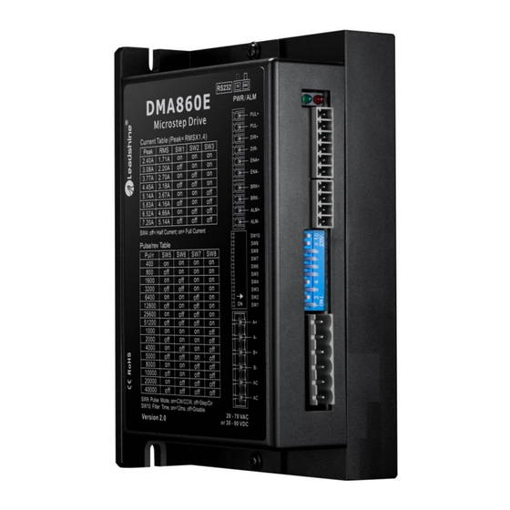
Connectors, DIP switches, and LED locations The DMA860E has three connector blocks P1&P2&P3 (see above picture). P1 is for control signals connections, and P2 is for output signals connections, P3 is for power and motor connections. The following tables are brief descriptions of the three connectors. -
Page 7: P3 - Motor And Power Supply Connector
3.4 P4 - Tuning Connector DMA860E has a tuning port with RS232 to modify the drive parameters, it is just used to modify parameter, not for equipment control because neither precision nor stability is sufficient. If you need a field bus drive, use a Leadshine RS485 or EtherCAT type drives: (http://www.leadshine.com/ProductSubType.aspx?type=products&category=stepper-products&producttype=stepper-dr... -
Page 8: Fault And Brake Output Connection
Fault Output When over voltage or over current protection happens, DMA860E red status LED light will blink and the impedance state between ALM+ and ALM- will change (from low to high or high to low depending on configuration) and can thus be detected. -
Page 9: Motor Connection
DMA860E Digital Stepper Drive User Manual 5. Motor Connection The DMA860E can drive 2-phase and 4-pahse bipolar hybrid stepper motors with 4, 6, or 8 wires. 5.1 Connections of 4-lead Motor The 4 lead motors are the least flexible and easy to connect. And the Speed – torque of motor depends on winding inductance. -
Page 10: Connections Of 8-Lead Motor
(frame size from NEMA 23 to 42) made by Leadshine or other motor manufacturers. To get good driving performances, it is important to select supply voltage and output current properly. Generally speaking, supply voltage determines the high speed performance of the motor, while output current determines the output torque of the driven motor (particularly at lower speed). -
Page 11: Power Supply Sharing
7. DIP Switch Configurations The DMA860E has one 10-bit DIP switch and one 1-bit selector. The first 10-bit is used to configure settings of micro step resolution, output current, motor standstill current, pulse type and smoothing time as shown below. -
Page 12: Output Current Configurations
DMA860E Digital Stepper Drive User Manual 51200 1000 2000 4000 5000 8000 10000 20000 40000 7.2 Output Current Configurations For a given motor, higher drive current will make the motor to output more torque, but at the same time causes more heating in the motor and drive. -
Page 13: Smoothing Time Configuration
12ms acceleration time. 7.3 Automatic Motor Matching & Self Configuration When powered on a DMA860E will automatically configure itself with the best settings to match the driven stepper motor for optimal performance. No action is needed. 8. Wiring Notes ... -
Page 14: Sequence Chart Of Control Signals
DMA860E Digital Stepper Drive User Manual 10. Sequence Chart of Control Signals In order to avoid some fault operations and deviations, PUL, DIR and ENA should abide by some rules, shown as following diagram: Figure 15: Sequence chart of control signals... -
Page 15: Troubleshooting
DMA860E Digital Stepper Drive User Manual 12. Troubleshooting In the event that your drive doesn’t operate properly, the first step is to identify whether the problem is electrical or mechanical in nature. The next step is to isolate the system component that is causing the problem.
Need help?
Do you have a question about the DMA860E and is the answer not in the manual?
Questions and answers