Table of Contents
Advertisement
Quick Links
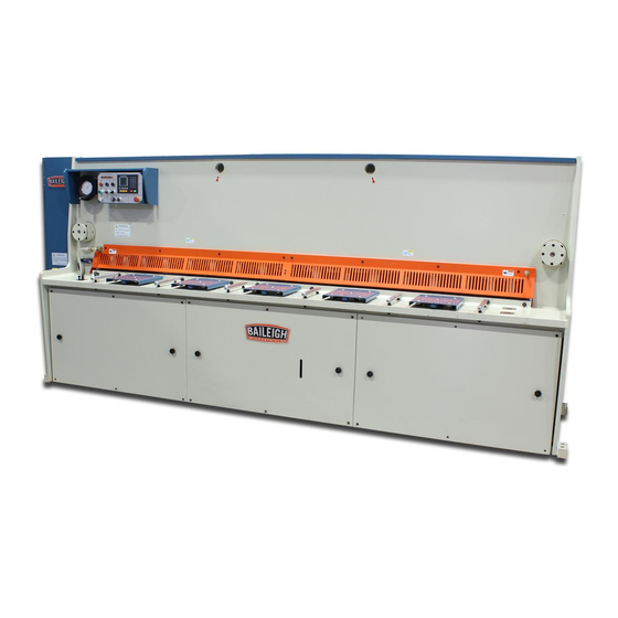
OPERATOR'S MANUAL
HYDRAULIC SHEAR
MODEL: SH-120250-HD
Baileigh Industrial Holdings LLC
P.O. Box 531
Manitowoc, WI 54221-0531
Phone: 920.684.4990
Fax: 920.684.3944
sales@baileigh.com
REPRODUCTION OF THIS MANUAL IN ANY FORM WITHOUT WRITTEN APPROVAL OF BAILEIGH INDUSTRIAL
HOLDINGS LLC IS PROHIBITED. Baileigh Industrial Holdings LLC, Inc. does not assume and hereby disclaims any
liability for any damage or loss caused by an omission or error in this Operator's Manual, resulting from accident,
negligence, or other occurrence.
Rev. 10/2019
© 2019 Baileigh Industrial Holdings LLC
Advertisement
Table of Contents
Troubleshooting

Related Manuals for Baileigh Industrial SH-120250-HD


Summary of Contents for Baileigh Industrial SH-120250-HD
- Page 1 REPRODUCTION OF THIS MANUAL IN ANY FORM WITHOUT WRITTEN APPROVAL OF BAILEIGH INDUSTRIAL HOLDINGS LLC IS PROHIBITED. Baileigh Industrial Holdings LLC, Inc. does not assume and hereby disclaims any liability for any damage or loss caused by an omission or error in this Operator’s Manual, resulting from accident, negligence, or other occurrence.
-
Page 2: Table Of Contents
Table of Contents THANK YOU & WARRANTY ..................1 INTRODUCTION ......................3 GENERAL NOTES ......................3 SAFETY INSTRUCTIONS ....................4 SAFETY PRECAUTIONS ....................6 Dear Valued Customer: ....................6 TECHNICAL SPECIFICATIONS ..................9 TECHNICAL SUPPORT ....................9 UNPACKING AND CHECKING CONTENTS ..............10 TRANSPORTING AND LIFTING .................. - Page 3 Multi-Step Programming .................... 42 Manual Movement ..................... 45 Parameter Setting ...................... 46 ALARM .......................... 48 Appendix Common Fault And Troubleshooting ............49 ALARM .......................... 50 Appendix A Common Fault and Troubleshooting ............51 Appendix B Alarm List ..................... 52 Appendix C Parameter Description ................. 53 MACHINE ADJUSTMENTS ..................
-
Page 4: Thank You & Warranty
THANK YOU & WARRANTY Thank you for your purchase of a machine from Baileigh Industrial Holdings LLC. We hope that you find it productive and useful to you for a long time to come. Inspection & Acceptance. Buyer shall inspect all Goods within ten (10) days after receipt thereof. Buyer’s payment shall constitute final acceptance of the Goods and shall act as a waiver of the Buyer’s rights to inspect or... - Page 5 We apologize for any discrepancies that may occur. Baileigh Industrial Holdings LLC reserves the right to make any and all changes deemed necessary in the course of business including but not limited to pricing, product specifications, quantities, and product availability.
-
Page 6: Introduction
INTRODUCTION The quality and reliability of the components assembled on a Baileigh Industrial Holdings LLC machine guarantee near perfect functioning, free from problems, even under the most demanding working conditions. However, if a situation arises, refer to the manual first. If a solution cannot be found, contact the distributor where you purchased our product. -
Page 7: Safety Instructions
IMPORTANT PLEASE READ THIS OPERATORS MANUAL CAREFULLY It contains important safety information, instructions, and necessary operating procedures. The continual observance of these procedures will help increase your production and extend the life of the equipment. SAFETY INSTRUCTIONS LEARN TO RECOGNIZE SAFETY INFORMATION This is the safety alert symbol. - Page 8 SAVE THESE INSTRUCTIONS. Refer to them often and use them to instruct others. PROTECT EYES Wear safety glasses or suitable eye protection when working on or around machinery. PROTECT AGAINST NOISE Prolonged exposure to loud noise can cause impairment or loss of hearing.
-
Page 9: Safety Precautions
HIGH VOLTAGE USE CAUTION IN HIGH VOLTAGE AREAS. DO NOT assume the power to be off. FOLLOW PROPER LOCKOUT PROCEDURES. EMERGENCY STOP BUTTON In the event of incorrect operation or dangerous conditions, the machine can be stopped immediately by pressing the E-STOP button. Twist the emergency stop button clockwise (cw) to reset. - Page 10 ! ..P SAFELY! LEASE ENJOY YOUR AILEIGH MACHINE LEASE ENJOY IT 1. FOR YOUR OWN SAFETY, READ INSTRUCTION MANUAL BEFORE OPERATING THE MACHINE. Learn the machine’s application and limitations as well as the specific hazards. 2. Only trained and qualified personnel can operate this machine. 3.
- Page 11 18. Keep children away. Children must never be allowed in the work area. DO NOT let them handle machines, tools, or extension cords. 19. Keep visitors a safe distance from the work area. 20. Store idle equipment. When not in use, tools must be stored in a dry location to inhibit rust. Always lock up tools and keep them out of reach of children.
-
Page 12: Technical Specifications
TECHNICAL SPECIFICATIONS Mild Steel Maximum Thickness .25" (6.35mm) Mild Steel* Stainless Steel Maximum Thickness .118" (3mm) Minimum Material Thickness 24ga (0.607mm) Shear Length 122" (3100mm) Blade Rake Angle .5° - 2.5° Manual Hand Wheel .002” - .024” (.05 - .60mm) Blade Clearance Strokes 14-45/min. -
Page 13: Unpacking And Checking Contents
UNPACKING AND CHECKING CONTENTS Your Baileigh machine is shipped complete. Separate all parts from the packing material and check each item carefully. Make certain all items are accounted for before discarding any packing material. WARNING: SUFFOCATION HAZARD! Immediately discard any plastic bags and packing materials to eliminate choking and suffocation hazards to children and animals. -
Page 14: Transporting And Lifting
TRANSPORTING AND LIFTING CAUTION: Lifting and carrying operations should be carried out by skilled workers, such as a truck operator, crane operator, etc. If a crane is used to lift the machine, attach the lifting chain carefully, making sure the machine is well balanced. -
Page 15: Installation
INSTALLATION IMPORTANT: Consider the following when looking for a suitable location to place the machine: • Overall weight of the machine. • Weight of material being processed. • Sizes of material to be processed through the machine. • Space needed for auxiliary stands, work tables, or other machinery. •... - Page 16 readjust and level to within 0.002”/39.5” (0.05/1000mm) and tighten the anchor bolts (The level should be placed on the support of lower blade for level adjustment). The tolerance in the machine's longitudinal and transversal directions .008”/39.5” (0.2/1000mm).
-
Page 17: Overall Dimensions
OVERALL DIMENSIONS... -
Page 19: Assembly And Set Up
ASSEMBLY AND SET UP WARNING: For your own safety, DO NOT connect the machine to the power source until the machine is completely assembled and you read and understand the entire instruction manual. Connecting the Foot Pedal 1. Unpack the foot pedal and route the plug connector to the bottom of the electrical enclosure. 2. -
Page 20: Guards And Light Curtains
Guards and Light Curtains 1. Unpack the left and right back guards and the support pads. 2. Install the support pads into each guard so that at least 1” (25mm) of thread is in the guard and the pad. 3. Set the initial length of the pad to be about 10” (254mm) from the bottom edge of the guard. - Page 21 11. Install the reflectors onto the inside of the right side back guard so that they are to toward the machine and pointing toward the far end of the machine. Note: When tightening the reflectors to the guard tube, slide the bracket outboard away from the shear as far as possible.
-
Page 22: Electrical
3-phase power source other than direct 3-phase. If you are using an alternate power source, consult a certified electrician or contact Baileigh Industrial Holdings LLC prior to energizing the machine. CAUTION: HAVE ELECTRICAL UTILITIES CONNECTED TO MACHINE BY A CERTIFIED ELECTRICIAN! Check if the available power supply is the same as listed on the machine nameplate. - Page 23 WARNING: In all cases, make certain the receptacle in question is properly grounded. If you are not sure, have a qualified electrician check the receptacle • Improper connection of the equipment-grounding conductor can result in risk of electric shock. The conductor with insulation having an outer surface that is green with or without yellow stripes is the equipment-grounding conductor.
- Page 24 Power cord connection: 1. Unlock and open the electrical enclosure door. 2. Insert a strain relief fitting into an open hole at the bottom of the electrical cabinet to grip the power cord (supplied by customer) and route a power cord into the cabinet to the top of the terminal strip at the upper right side of the cabinet (XT1).
-
Page 25: Controls Functions
CONTROLS FUNCTIONS Used to set and store bending parameters for either single or YSD6000 programmed usage. Displays the rake angle of the upper blade in degrees as DRO (Digital Read compared to the lower stationary blade. This is a display and Out) does not program or control the rake angle. -
Page 26: Systems Operation
Sets the system to function with the operator full foot pedal Stroke Cycle Switch stroke control or operator single touch foot pedal stroke control. Motor Start/Run Press to start and run the hydraulic pump. The switch button Switch will illuminate green when the pump motor is running. In the event of an unwanted or unsafe condition, press the E- Emergency Stop Stop to stop all machine functions. -
Page 27: Operation Procedure
Operation Procedure 1. Turn ON the main power disconnect switch and press the motor start button to start the motor. 2. If not already completed during the wiring, inspect if the motor is rotating in the correct direction as by the arrow on the motor fan cover. If not, stop the motor and change the wiring immediately. -
Page 28: Blade Clearance Adjustment
Blade Clearance Adjustment To obtain a high-quality shearing section, a suitable blade clearance must be selected according to the material to be cut. This shear is equipped with a fast adjustment handwheel for blade clearance. Note: This is a general guide for setting the blade gap. Your specific settings may change based upon several factors regarding specific material and other machine settings and conditions. -
Page 29: Material Selection
MATERIAL SELECTION CAUTION: It must be determined by the customer that materials being processed through the machine are NOT potentially hazardous to operator or personnel working nearby. When selecting materials keep these instructions in mind: • Material must be clean and dry. (without oil) •... -
Page 30: Return Stroke
Return Stroke When the cutting beam reaches the return point, coil YA2 is deenergized. With no valve energized the hydraulic pump will run at idle with fluid flowing back to tank. At the same time pressurized oil from the accumulator will reverse the flow of oil into the cylinders causing the beam to rise back to the TDP. -
Page 31: Electrical System Operation
ELECTRICAL SYSTEM OPERATION CAUTION: Always wear proper eye protection with side shields, safety footwear, and leather gloves to protect from burrs and sharp edges. When handling large heavy materials make sure they are properly supported. Main power switch Turn the main disconnect switch QS located on the back side of electrical cabinet ON, the power indicator HL1 lights. -
Page 32: Rack Angle
Rack Angle Push the SB7 (+) button and the valve YA3 is energized. When the other hydraulic and mechanical functions are met, the rack angle will increase until it contacts the limit switch SQD. Push the SB6 (-) button and the relay KA2, KT3 and valve YA1, 2, and 3 are energized. When the other hydraulic and mechanical functions are met, the rack angle will increase until it contacts the limit switch SQC. -
Page 33: Accumulator Charging
Accumulator Charging Important: This is not a common function. The accumulator has been charged from the factory and will not require charging unless someone has tempered with or inadvertently actuated the accumulator hydraulic circuit ball valve. This story is only intended to provide understanding of the accumulator circuit. -
Page 34: Operation Instruction, Ysd6000S
OPERATION INSTRUCTION, YSD6000s Keys Clear/Delete key, clear current numbers entered Enter: in programming interface, press this key to confirm the parameter entered. Stop, Stops operation and the LED in the corner will illuminate. Start, to let the controller operate in the automatic running interface. The LED in the corner will illuminate when running. - Page 35 Interface switching, mainly used to switch among parameter interface, programming interface and diagnose interface and to modify in program sequence. Left Direction key, moves the cursor to the left or page back. Right Direction key, moves the cursor right or page forward. Cursor up, press this key to show previous parameter.
-
Page 36: Display Screen
Low speed forward moving key. High/low speed selection, press this key to output high speed and release to output low speed key. Display Screen The display screen is a 160 x 160 dot matrix LCD display. • Title bar: display relevant information of current page, such as its name, Title Bar etc. -
Page 37: Basic Operation Flowchart
BASIC OPERATION FLOWCHART The controller interface switches as the flowchart shows as follows: Power On Manual Single Run Single-Step Programs Multi-Step Multi-Step Run Const IO Monitor Alarm Record Password XXXXX Password 5656 Password 1212 System Diagnose TchIn PARA Parameter... -
Page 38: Operation Examples
Start and Stop After finishing the programming, press to run the device. The device starts, the green indicator light will be on. Only on the SINGLE page, PROAGRAM page or STEP page, the machine can run after pressing . In other pages, press to run is invalid. - Page 39 Parameter Setting 6.00” Not used. 0.2” 80 (typical default. Normally does not change. Others According to the actual situation to set. 1. Power on, the device displays the single-step parameter page automatically. 2. Press either the , or arrow keys to highlight and then modify the selected parameter.
- Page 40 This operation will edit and save in the number 2 program folder setting the following parameters on the PROGRAM page. Page Parameter Setting PROGRAM 4” Not used. 1 / 3ST 0.25” Repeat Times 12” Not used. 2 / 3ST 0.25” Repeat Times 24”...
- Page 41 4. Press the enter button to enter the number 2 folder program page. 5. Using the information from the chart above, press either the , or arrow keys to highlight and then modify the selected parameter. 6. Press the arrow button to enter 1/3ST page, and modify the parameters using the information in the 1 / 3ST row of the chart above.
-
Page 42: Programming
8. Repeat the steps for the 3 / 3ST page. 9. Press the button to switch to PROGRAMS manage page. 10. Press the start button to run the device. The device will enter the running page. PROGRAMMING This device has two programming methods, which are single-step programming and multi-step programming. - Page 43 3. Use the numerical keys to input program value and then press the enter button to complete input. 4. Press the start button to run the device. The device will enter the running page. 5. Press to stop the machine and return to the SINGLE screen. Note: Parameter can only be set when Stop indicator is on.
- Page 44 Operation example On single-step program page, program back gauge position to 6 inches, retract distance to 0.1 inches, work piece to 0. Operation steps are shown in Table 2-2. Table 2-2 Operation steps of single step example Operation Steps Operation Step 1 down arrow to select “XP”...
-
Page 45: Multi-Step Programming
Multi-Step Programming Multi-step program is used for processing single work piece of different processing steps, realize consecutive implementation of multi-steps, and improve processing efficiency. Operation Steps 1. Power on, the device displays the single-step parameter page automatically. 2. Press the button to switch to program manage page as shown. - Page 46 The description of the PROGRAM parameters Parameter Default Range Unit Description 0-25 The total number of steps in this program. The number of processing workpiece in this 0-99999 program. PP = O: This value is the current work piece. 0-99999 PP >...
- Page 47 11. Press the button to switch to PROGRAMS manage page. Description of Step parameters Parameter Default Range Unit Description 0.00 -9999.999 - 9999.999 mm/inch Program position of X-axis. Not Active 0.00 0 - 9999.999 mm/inch Retract distance of X axle. Cut Length Not Active Repeat Times 1...
-
Page 48: Manual Movement
Step 11 Press the arrow to return to the setup page of the first step. Press the start button and the system will execute according to this Step 12 program. Note: • In completion of multi-step programming, return to start step before launching the system; otherwise the program will start position processing at the current step. -
Page 49: Parameter Setting
Parameter Setting User can setup all parameters required for normal operation of the system, including system parameter and X axis parameter. Operation Steps 1. On program management page, press the button to enter programming constant page, as shown in Figure 2-8. On this page, programming constant can be set. Figure 2-8 Programming constant page Range of programming constant setup is shown in Table 2-5. - Page 50 2. Input password "1212", press to enter system parameter setting page, as shown in Figure 2-9. SYS PARA 1/1PG X digits: X-safe: 1.000 Step Delay: 0 ~ 3 : Range: Figure 2-9 System parameter setting page Step up parameter, parameter setup range is shown in Table 2-6. Table 2-6 system parameter setup range Parameter range Unit...
-
Page 51: Alarm
ALARM The device can detect internal or external abnormalities automatically and send out alarm prompt. The alarm messages are available on alarm list. Operation steps 1. On the programming management page, press the button to enter programming constant page. 2. On the programming constant page, press the arrow button to enter "Alarm History"... -
Page 52: Appendix Common Fault And Troubleshooting
Appendix Common Fault And Troubleshooting Fault Symptom Troubleshooting When power on, the device will not Check whether No. 1 (24V) and No.2 (OV) terminal display. is connected or not, or signal is reversed. When X axis programming is operating, the back gauge motor does Check wiring to motor not move. -
Page 53: Alarm
ALARM The device can detect internal or external abnormalities automatically and send out alarm prompt. The alarm message are available on alarm list. Operation steps 1. On the CONST page, press the , button to enter IO Monitor page. 2. On the CONST page, press the arrow button to enter "Alarm Record"... -
Page 54: Appendix A Common Fault And Troubleshooting
Appendix A Common Fault and Troubleshooting Fault Troubleshooting The electrode of power supply terminal is connected error; please see the information of power When power on, the device will not nameplate. display. Voltage is too low. Electrical outlet is not connected. Check whether mechanical part has been locked or When program is operating, motor slider (ram) returns to Upper Dead Point. -
Page 55: Appendix B Alarm List
Appendix B Alarm List Alarm NO. Alarm Information Alarm Description A.01 Pieces reached Normal message, that the count reaches a preset value. The current position of X-axis is out of the minimum value, A.02 X Pos <minimum it is necessary to move the X-axis to the soft limit range manually. -
Page 56: Appendix C Parameter Description
Appendix C Parameter Description Parameter Default Range Unit Description CONST 0: mm mm/inch 1: inch 0: Chinese Chinese/English 1: English The current software version Version number. TchIn PARA When the teaching of X-axis is enabling, the operator assigns X-tea. in 10.00 0-9999.999 mm/inch... - Page 57 work piece. STEP -9999.999 ⁓ 0.00 mm/inch Program position of X-axis. 9999.999 0.00 0-99.99 mm/inch Program position of G-axis. 0.00 0-9999.999 mm/inch Retract distance of X axle. Actual time of the cut length = Cut Length 0-100 Max time of the cut length XCut Length Repeat Times 1-99...
-
Page 58: Machine Adjustments
MACHINE ADJUSTMENTS WARNING: Whenever possible, be sure the electrical disconnect is OFF before working on the machine. Adjustments should be performed as needed by qualified personnel. Because some adjustments require the machine to be operational, ALWAYS follow proper safety precautions when working on or around any machinery. Back Gauge Alignment Following the norm, the clearance evenness between the stopper of back gauge and the lower blade should be 0.1mm/m. - Page 59 The procedures for the readjustment of blade clearance: 1. Reduce the rake angle until the upper blade is parallel to the lower blade. 2. Turn the main motor off and loose slowly the braking valve (No. 13) (see the hydraulic scheme) until the upper and lower blades are overlapped for 1mm and then tighten the valve.
- Page 60 BAILEIGH INDUSTRIAL HOLDINGS LLC 1625 D , WI 54220 UFEK RIVE ANITOWOC : 920. 684. 4990 F : 920. 684. 3944 HONE www.baileigh.com BAILEIGH INDUSTRIAL HOLDINGS LTD. U WIFT OINT WIFT ALLEY NDUSTRIAL STATE UGBY , CV21 1QH U IDLANDS...
Need help?
Do you have a question about the SH-120250-HD and is the answer not in the manual?
Questions and answers