Table of Contents
Advertisement
OPERATOR'S MANUAL
BOX AND PAN BRAKE
MODEL: BB-12014
Baileigh Industrial, Inc.
P.O. Box 531
Manitowoc, WI 54221-0531
Phone: 920.684.4990
Fax: 920.684.3944
sales@baileigh.com
REPRODUCTION OF THIS MANUAL IN ANY FORM WITHOUT WRITTEN APPROVAL OF BAILEIGH INDUSTRIAL, INC.
IS PROHIBITED. Baileigh Industrial, Inc. does not assume and hereby disclaims any liability for any damage or loss
caused by an omission or error in this Operator's Manual, resulting from accident, negligence, or other occurrence.
Rev. 09/2015
© 2015 Baileigh Industrial, Inc.
Advertisement
Table of Contents

Related Manuals for Baileigh Industrial BB-12014


Summary of Contents for Baileigh Industrial BB-12014
- Page 1 REPRODUCTION OF THIS MANUAL IN ANY FORM WITHOUT WRITTEN APPROVAL OF BAILEIGH INDUSTRIAL, INC. IS PROHIBITED. Baileigh Industrial, Inc. does not assume and hereby disclaims any liability for any damage or loss caused by an omission or error in this Operator’s Manual, resulting from accident, negligence, or other occurrence.
-
Page 2: Table Of Contents
Table of Contents THANK YOU & WARRANTY ..................1 INTRODUCTION ......................3 GENERAL NOTES ......................3 SAFETY INSTRUCTIONS ....................4 SAFETY PRECAUTIONS ....................6 TECHNICAL SPECIFICATIONS ..................8 TECHNICAL SUPPORT ....................8 UNPACKING AND CHECKING CONTENTS ..............9 Cleaning ........................9 TRANSPORTING AND LIFTING .................. -
Page 3: Thank You & Warranty
THANK YOU & WARRANTY Thank you for your purchase of a machine from Baileigh Industrial. We hope that you find it productive and useful to you for a long time to come. Inspection & Acceptance. Buyer shall inspect all Goods within ten (10) days after receipt thereof. Buyer’s payment shall constitute final acceptance of the Goods and shall act as a waiver of the Buyer’s rights to inspect or... - Page 4 A 30% re-stocking fee applies to all returns. Baileigh Industrial makes every effort to ensure that our posted specifications, images, pricing and product availability are as correct and timely as possible. We apologize for any discrepancies that may occur. Baileigh Industrial reserves the right to make any and all changes deemed necessary in the course of business including but not limited to pricing, product specifications, quantities, and product availability.
-
Page 5: Introduction
After receiving your equipment remove the protective container. Do a complete visual inspection, and if damage is noted, photograph it for insurance claims and contact your carrier at once, requesting inspection. Also contact Baileigh Industrial and inform them of the unexpected occurrence. Temporarily suspend installation. -
Page 6: Safety Instructions
IMPORTANT PLEASE READ THIS OPERATORS MANUAL CAREFULLY It contains important safety information, instructions, and necessary operating procedures. The continual observance of these procedures will help increase your production and extend the life of the equipment. SAFETY INSTRUCTIONS LEARN TO RECOGNIZE SAFETY INFORMATION This is the safety alert symbol. - Page 7 SAVE THESE INSTRUCTIONS. Refer to them often and use them to instruct others. PROTECT EYES Wear safety glasses or suitable eye protection when working on or around machinery. PROTECT AGAINST NOISE Prolonged exposure to loud noise can cause impairment or loss of hearing.
-
Page 8: Safety Precautions
SAFETY PRECAUTIONS Metal working can be dangerous if safe and proper operating procedures are not followed. As with all machinery, there are certain hazards involved with the operation of the product. Using the machine with respect and caution will considerably lessen the possibility of personal injury. However, if normal safety precautions are overlooked or ignored, personal injury to the operator may result. - Page 9 11. Use eye and ear protection. Always wear ISO approved impact safety goggles. Wear a full- face shield if you are producing metal filings. 12. Do not overreach. Maintain proper footing and balance at all times. DO NOT reach over or across a running machine.
-
Page 10: Technical Specifications
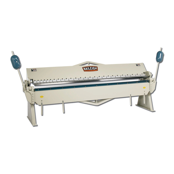
**100000 PSI – stainless steel DESCRIPTION The Baileigh Model BB-12014 Box and Pan Brake is hand operated and capable of bending up to 14ga. (2mm) mild steel and 18ga. (1.25mm) stainless x 120” (3048mm) lg. The machine has 26 removable fingers and a 6” (152mm) box depth allowing it to fabricate pans, boxes, channels, angles, and other shapes. -
Page 11: Unpacking And Checking Contents
UNPACKING AND CHECKING CONTENTS Your Baileigh machine is shipped complete. Separate all parts from the packing material and check each item carefully. Make certain all items are accounted for before discarding any packing material. WARNING: SUFFOCATION HAZARD! Immediately discard any plastic bags and packing materials to eliminate choking and suffocation hazards to children and animals. - Page 12 Remove the top portion of the crate. Take off the nuts and remove the supports (1) from the pallet. Remove the loose parts and set aside. Remove the nuts securing the main body (2) to the pallet. ...
- Page 13 Item Description Qty. Brake Main Body Supports Counterweight Assemblies Open End Wrench Handles w/Bolts & Lockwashers Stop Rod w/Cotter Pin Hex Bolt ½-13x1.75” Lg. Lock washer ½” Flatwasher Hex Nut ½-13...
-
Page 14: Transporting And Lifting
TRANSPORTING AND LIFTING IMPORTANT: Lifting and carrying operations should be carried out by skilled workers, such as a truck operator, crane operator, etc. If a crane is used to lift the machine, attach the lifting chain carefully, making sure the machine is well balanced. Follow these guidelines when lifting with truck or trolley: ... -
Page 15: Installation
INSTALLATION IMPORTANT: Consider the following when looking for a suitable location to place the machine: Overall weight of the machine. Weight of material being processed. Sizes of material to be processed through the machine. Space needed for auxiliary stands, work tables, or other machinery. ... -
Page 16: Anchoring The Machine
(7.87mm) the stand. This machine requires a solid floor such as concrete at a minimum of 4” (102mm) thick. 6” (153mm) minimum is preferred. .50" (12.7mm) 2.00" 126.00" (51mm) (3200mm) Clearance for 5/8" bolt (16mm) BB-12014 mounting holes 1.50" (38mm) -
Page 17: Overall Dimensions
OVERALL DIMENSIONS 163.00” (4140mm) 130.00” (3302mm) 56.00” (1422mm) 67.00” (1702mm) 48.50” (1232mm) 33.50” (851mm) -
Page 18: Getting To Know Your Machine
GETTING TO KNOW YOUR MACHINE Item Description Function Counterweight Adjustable weights to assist in raising the bending leaf. Clamping Leaf Secures the piece part against the clamping block. Finger Blocks Movable dies that the piece part is bent against. Clamping Handles Used to raise, lower, and lock the clamping leaf. -
Page 19: Installation Assembly
INSTALLATION ASSEMBLY Removing Finger Assemblies To remove the finger block assemblies you must first raise the clamping leaf with the clamping handles. Now for each finger block, loosen the capscrew shown in (fig. 3) and slide the finger assembly off of the finger guide. After thoroughly cleaning each finger assembly, coat them with a metal protectant to prevent corrosion. - Page 20 figure 6 figure 5 WARNING: DO NOT position yourself under the main body at any time while attaching the supports. 4. Raise the main body from the pallet, avoiding sudden accelerations or quick changes of direction and carefully pull the pallet out of the way. 5.
-
Page 21: Attaching The Handles
Attaching the Handles Locate and secure the (4) handles to the backside of the bending plate with (8) M10 x 40mm lg. capscrews, flat washers, and lock washers as shown. figure 8 Installing the Counterweights 1. Loosen the (2) jamnuts and back out the hex bolts of each counterweight pocket for clearance. -
Page 22: Mounting The Stop Rod
Mounting the Stop Rod Cotter pin 1. Loosen the (2) socket head bolts on the stop collar and remove from the stop rod. 2. Insert the stop rod into the rotating stop block. 3. Push the short end of the stop rod into the tab on the bending leaf and secure with the cotter pin (supplied). -
Page 23: Setup And Adjustments
SETUP AND ADJUSTMENTS Finger Alignment After removing and cleaning the fingers they must be aligned correctly to assure a proper bend. They can be aligned either as a group or individually. 1. Make sure there is no downward pressure on the fingers by first disengaging the two clamping handles. -
Page 24: Adjusting The Setback
Adjusting the Setback Setback Finger Distance Setback is the distance from the front edge of the finger to the front edge of the clamp block as shown in (fig. 14). This distance is determined by the gauge (thickness) Bending Wing of the piece part and inside radius of the bend. -
Page 25: Positioning The Stop Collar
Positioning the Stop Collar The stop collar is used for repeat bending when you want the bending leaf to stop at the same position each time. 1. Loosen the stop collar and make your bend, stopping at the top of the bend. -
Page 26: Adjusting The Clamping Pressure
Adjusting the Clamping Pressure CAUTION: Excessive clamping pressure can “pre load” and permanently distort the brake. DO NOT bend material heavier than the rated capacity, even in shorter lengths. Use material with square-sheared edges. (a rolled edge will cause bowing). ... -
Page 27: Counterweight Adjustments
Counterweight Adjustments CAUTION: DO NOT allow the weight to free fall down the shaft or fall off the shaft where it might cause personal injury. DO NOT lower the weights to a point where they restrict the motion of the locking clamp arms. The counterweights provide added leverage when bending thicker piece parts. -
Page 28: Bending Leaf Edge Alignment
Crowning adjustment is made by tightening or loosening the center leaf nuts (C and D). 1. Move the clamp handles to the forward position. 2. If the bend is open on the middle as in example (B), evenly tighten the top leaf center truss nut (C) and the lower leaf center truss nut (D) 1/2 turn each and test the bend angle. -
Page 29: Operation
OPERATION CAUTION: Always wear proper eye protection with side shields, safety footwear, and leather gloves to protect from burrs and sharp edges. CAUTION: Keep hands and fingers clear of the clamping beam. Stand off to the side of the machine to avoid getting hit with the bending apron as it comes up to bend. -
Page 30: Understanding Springback
UNDERSTANDING SPRINGBACK Springback, also known as elastic recovery, is the result of the metal wanting to return to its original shape after undergoing compression and stretch. After the bending leaf is removed from the metal and the load is released, the piece part relaxes, forcing the bent portion of the metal to return slightly to its original shape. -
Page 31: Lubrication And Maintenance
LUBRICATION AND MAINTENANCE WARNING: Maintenance should be performed on a regular basis by qualified personnel. Always follow proper safety precautions when working on or around any machinery. Check daily for any unsafe conditions and fix immediately. Check that all nuts and bolts are properly tightened. ... -
Page 32: Beam Parts Identification Drawing
BEAM PARTS IDENTIFICATION DRAWING... -
Page 33: Bending Leaf Parts Identification Drawing
BENDING LEAF PARTS IDENTIFICATION DRAWING... -
Page 34: Parts List
Parts List Item Description Qty. Bending leaf assembly Handle bar Screw Bottom bar Round screw Angle bar Round head screw Hinge (R.H.) Hinge (L.H.) Hinge rod Round head screw Hex head screw Hex set screw Round head screw Counterweight rod Counterweight assembly Stand assembly Hex head screw... -
Page 35: Troubleshooting
Item Description Qty. U-clamp (assorted widths) 3”, 4”, 5”, & 6” Soc. head screw Finger holder (assorted widths) 3”, 4”, 5”, & 6” Finger washer (assorted widths) 3”, 4”, 5”, & 6” Finger (assorted widths) 3”, 4”, 5”, & 6” Spring cover assembly Bracket bar Shaft, clamp handle... - Page 36 , WI 54220 UFEK RIVE ANITOWOC : 920. 684. 4990 F : 920. 684. 3944 HONE www.baileigh.com BAILEIGH INDUSTRIAL, INC. 1455 S. C , CA 91761 AMPUS VENUE NTARIO : 920. 684. 4990 F : 920. 684. 3944 HONE BAILEIGH INDUSTRIAL LTD. U...
Need help?
Do you have a question about the BB-12014 and is the answer not in the manual?
Questions and answers