Table of Contents
Advertisement
Quick Links
Advertisement
Table of Contents

Related Manuals for Baileigh Industrial B8075


Summary of Contents for Baileigh Industrial B8075
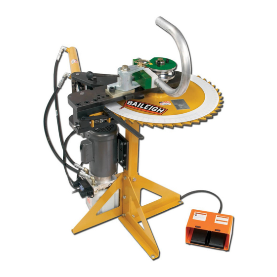
- Page 1 OPERATOR’S MANUAL ROTARY DRAW BENDER MODEL: RDB-125 (B8075)
-
Page 2: Table Of Contents
TABLES, CHARTS, & DIAGRAMS ................31 Diagram 1 ........................34 Diagram2 ........................35 PARTS DIAGRAM ......................36 Power Unit Assembly Parts Diagram ................. 36 Stand Assembly Parts Diagram ................. 37 Main Frame Assembly Parts Diagram ............... 38 Rev. 03/2015 © 2015 Baileigh Industrial, Inc. - Page 3 Spring Back Lever Assembly Parts Diagram ............. 39 Ratchet Wheel Assembly Parts Diagram ..............40 Swing Arm Assembly Parts Diagram ................. 41 Spring Latch Assembly Parts Diagram ..............42 Cylinder Assembly Parts Diagram ................43 Parts List ........................44...
-
Page 4: Introduction
INTRODUCTION The quality and reliability of the components assembled on a Baileigh Industrial machine guarantee near perfect functioning, free from problems, even under the most demanding working conditions. However if a situation arises, refer to the manual first. If a solution cannot be found, contact the distributor where you purchased our product. -
Page 5: Safety Instructions
Note: This symbol refers to useful information throughout the manual. IMPORTANT PLEASE READ THIS OPERATORS MANUAL CAREFULLY It contains important safety information, instructions, and necessary operating procedures. The continual observance of these procedures will help increase your production and extend the life of the equipment. SAFETY INSTRUCTIONS LEARN TO RECOGNIZE SAFETY INFORMATION This is the safety alert symbol. - Page 6 General precautions are listed on CAUTION safety signs. CAUTION also calls attention to safety messages in this manual. SAVE THESE INSTRUCTIONS. Refer to them often and use them to instruct others. PROTECT EYES Wear safety glasses or suitable eye protection when working on or around machinery.
- Page 7 BEWARE OF PINCH POINTS Keep hands and fingers away from the drive mechanisms, cylinders, ratchets, and other moving linkage while the machine is in operation. KEEP CLEAR OF MOVING OBJECTS Always be aware of the position of the material and the swing area in which the material will travel.
-
Page 8: Safety Precautions
SAFETY PRECAUTIONS Metal working can be dangerous if safe and proper operating procedures are not followed. As with all machinery, there are certain hazards involved with the operation of the product. Using the machine with respect and caution will considerably lessen the possibility of personal injury. However, if normal safety precautions are overlooked or ignored, personal injury to the operator may result. - Page 9 11. Do not overreach. Maintain proper footing and balance at all times. DO NOT reach over or across a running machine. 12. Stay alert. Watch what you are doing and use common sense. DO NOT operate any tool or machine when you are tired. 13.
-
Page 10: Technical Specifications
TECHNICAL SPECIFICATIONS Maximum Center Line Radius (CLR)* 10.5" (266mm) Minimum Center Line Radius (CLR)* .5" (12.7mm) Minimum OD .25" (6.35mm) Mild Steel Pipe (Schedule 40) Based on a material tensile strength of 60000 PSI – mild 2" (50.8mm) steel Aluminum Pipe (Schedule 40) 2"... -
Page 11: Unpacking And Checking Contents
UNPACKING AND CHECKING CONTENTS Your Baileigh machine is shipped complete in one crate. Separate all parts from the packing material and check each item carefully. Make certain all items are accounted for before discarding any packing material. WARNING: SUFFOCATION HAZARD! Immediately discard any plastic bags and packing materials to eliminate choking and suffocation hazards to children and animals. -
Page 12: Transporting And Lifting
TRANSPORTING AND LIFTING CAUTION: Lifting and carrying operations should be carried out by skilled workers, such as a truck operator. Make sure the machine is well balanced. Choose a location that will keep the machine free from vibration and dust from other machinery. Keep in mind that having a large clearance area around the machine is important for safe and efficient working conditions. -
Page 13: Assembly And Set Up
• Remove scrap and waste materials regularly, and make sure the work area is free from obstructing objects. • If long lengths of material are to be fed into the machine, make sure that they will not extend into any aisles. •... -
Page 14: Getting To Know Your Machine
GETTING TO KNOW YOUR MACHINE... -
Page 15: General Design Description
Item Description Function Forward Foot Pedal Will operate the machine in the cw direction Reverse Foot Pedal Will operate the machine in the ccw direction Hydraulic Reservoir Holds the oil for operating the hydraulics. Hydraulic Pump and Valve Provides and controls the oil flow. Assembly Electric Motor Provides the power to power the hydraulics. -
Page 16: Electrical
ELECTRICAL CAUTION: HAVE ELECTRICAL UTILITIES CONNECTED TO MACHINE BY A CERTIFIED ELECTRICIAN! Check if the available power supply is the same as listed on the machine nameplate. WARNING: Make sure the grounding wire (green) is properly connected to avoid electric shock. DO NOT switch the position of the green grounding wire if any electrical plug wires are switched during hookup. - Page 17 • Improper connection of the equipment-grounding conductor can result in risk of electric shock. The conductor with insulation having an outer surface that is green with or without yellow stripes is the equipment-grounding conductor. If repair or replacement of the electric cord or plug is necessary, do not connect the equipment-grounding conductor to a live terminal.
-
Page 18: Operation
OPERATION CAUTION: Always wear proper eye protection with side shields, safety footwear, and leather gloves to protect from burrs and sharp edges. CAUTION: Keep hands and fingers clear of the dies and swing arms. Stand to the front of the machine to avoid getting hit with the material during the bending process. -
Page 19: Material Removal
7. After full extension, press the reverse foot pedal, as the drive lever retracts, the anti- springback lock pin will hold the ratchet wheel in place. You can restart the bending process at any tooth on the ratchet wheel or return the machine to the home position and get the maximum degrees per stroke. -
Page 20: Die Selection And Installation
DIE SELECTION AND INSTALLATION Before any bending can take place, the proper die set must be chosen to match the material being bent. (EX) 1-1/2” diameter tubing requires a die set marked 1-1/2” tube. Hook Arm Bend Die Hold down Bolts Plastic Slide Counter Die Mount Bronze Counter Die Insert... - Page 21 3. Install and tighten the 1/2-13 socket head bolts provided with the die. Tighten these bolts enough to hold the die firmly down to the spindle. Approximately 30-40ft-lb. (40- 50N•m). IMPORTANT: FAILURE TO PROPERLY BOLT DOWN DIE WILL RESULT IN DAMAGE TO MACHINE AND TOOLING. 4.
- Page 22 Incorrect Counterdie Position Too far away from die Touching die Correct Counter Die Position Approximately 1/8” (3mm) away IMPORTANT: Be sure the long end of the counter die points away from the hook arm, or to the right of machine.
-
Page 23: Material Insertion
Material Insertion 1. Once the die set is properly installed, the material that matches the die can be inserted (I.E. 1-1/4”tube would go into a die mark D-1250T-R***). 2. Open the counter die quick release assembly and insert the material past the hook arm. The start of bend mark is engraved with an “O”... -
Page 24: Material Insertion Limitations
Material Insertion Limitations Left Right • The left figure shows the recommended minimum / correct amount of material remaining to be fully supported in plastic slide. • The right figure shows the maximum amount the material can be pulled through the counterdie. -
Page 25: Bending More Than 180 Degrees
Bending More than 180 Degrees • This machine is capable of bending more than 180 degrees. Contact your distributor about your application. o It will require a password to make the machine go past 200 degrees. o Requires special tooling to allow removal of bent part. If standard tooling is used, the material will be locked onto the die. - Page 26 This software is available from Baileigh Industrial. Contact your distributor. • Bending with a rotary draw bender requires determining the start of bend point which will line up with the “0”...
-
Page 27: Pipe And Tube Bending Diagrams
PIPE AND TUBE BENDING DIAGRAMS L = Arc length (outside) R = Rise (inside) D = Tube outside diameter t = Tube wall thickness a = First bend arc angle H = Height of offset b = Second bend arc angle L = Length of offset A = First tangent R1 = First radius... -
Page 28: Bending Glossary
BENDING GLOSSARY Arc Length The length of material along the centerline of the tubing Distance in inches from the center of curvature to the centerline Centerline Radius (CLR) axis of the tube bending or pipe bending bends. Abbreviated as CLR. See Tube Bending and Pipe Bending Diagram Angle in degrees to which the tube/pipe bends are formed (i.e. -
Page 29: Bending Suggestions
BENDING SUGGESTIONS Aluminum Bending If bending aluminum, lubrication is very important, if the results are less than desirable with WD- 40 other lubricants can be used such as: • Johnson Paste Wax (seems to work the best) • High Pressure grease •... -
Page 30: Bending With Square Dies
Bending With Square Dies • Die Parts Main Bending Die Die Cap Quick Release Handles Hook-Arm Hook-Arm Clamp Plastic Slide Slide Mount Quick Release Studs Square Tooling Setup 1. Install the bending die (1) on to the spindle. Be careful not to pinch your fingers as you lower the die on to the spindle. -
Page 31: Large Size Square
6. If the material slips during the bending operation, install the hook arm clamp (5). Do not use it unless you have to. 7. Activate the bender and bend to the desired angle. 8. To remove the material, open the counter die and return bender to the “home position”. Using a soft mallet, gently tap the cap clamps open and the material will spring out of the die (1). -
Page 32: Lubrication And Maintenance
LUBRICATION AND MAINTENANCE WARNING: Make sure the electrical disconnect is OFF before working on the machine. Maintenance should be performed on a regular basis by qualified personnel. Always follow proper safety precautions when working on or around any machinery. • Check daily for any unsafe conditions and fix immediately. •... -
Page 33: Rdb-125 Electrical Schematic
RDB-125 ELECTRICAL SCHEMATIC... -
Page 34: Tables, Charts, & Diagrams
TABLES, CHARTS, & DIAGRAMS Table 1 Standard Pipe Sizes and Schedules PIPE O.D. Pipe Schedules and Wall Thickness SIZES XX STRONG 0.405 0.400 0.050 0.068 0.095 0.540 0.500 0.070 0.088 0.119 0.675 0.500 0.070 0.091 0.126 0.840 0.700 0.080 0.109 0.147 0.188 0.294... - Page 35 Table 3 ARC LENGTH TABLE EXAMPLE: Arc Length = Constant x Bend Radius. Example: 90deg bend with 6” clr EXAMPLE: 1.575 (from table) x 6” (clr) = 9.45” (Arc Length) For bends more than 90deg, Constants can be added together. Degrees Constant Degrees...
- Page 36 Table 4 Counter Die Placement Chart 1" THICK 1.5" THICK 2" THICK (Centerline COUNTERDIES COUNTERDIES COUNTERDIES Radius) #N/A #N/A SILVER HOLE# 1 #N/A SILVER HOLE# 1 GOLD HOLE# 1 SILVER HOLE# 1 GOLD HOLE# 1 SILVER HOLE# 2 GOLD HOLE# 1 SILVER HOLE# 2 GOLD HOLE #2 SILVER HOLE# 2...
-
Page 37: Diagram 1
Diagram 1... -
Page 38: Diagram2
Diagram2... -
Page 39: Parts Diagram
PARTS DIAGRAM Power Unit Assembly Parts Diagram... -
Page 40: Stand Assembly Parts Diagram
Stand Assembly Parts Diagram... -
Page 41: Main Frame Assembly Parts Diagram
Main Frame Assembly Parts Diagram... -
Page 42: Spring Back Lever Assembly Parts Diagram
Spring Back Lever Assembly Parts Diagram... -
Page 43: Ratchet Wheel Assembly Parts Diagram
Ratchet Wheel Assembly Parts Diagram... -
Page 44: Swing Arm Assembly Parts Diagram
Swing Arm Assembly Parts Diagram... -
Page 45: Spring Latch Assembly Parts Diagram
Spring Latch Assembly Parts Diagram... -
Page 46: Cylinder Assembly Parts Diagram
Cylinder Assembly Parts Diagram... -
Page 47: Parts List
Parts List Part Number Description Qty. ME-M100-6A026 Stand Tube ME-M100-6A025 Leg Brace M12 x 1.75 x 25 Hex Flange ME-M100-6A014-V2 Base Plate ME-M125-6A014 Pump Mounting Plate (Taiwan) M8 x 1.25 x 14 Hex Flange ME-M125-7A009 Motor Spacer Imperial 3/8 Lock Washer ME-M125-6A002 Bottom Plate ME-M125-7A001... - Page 48 Part Number Description Qty. M150-6A019 5/8 Drive Key M300-7A031 Thrust Washer ME-M125-5A003 Ratchet Wheel M12 x 1.75 x 50 SHCS ME-M125-6A005 Bottom Lever Arm PP-0294 Flanged Sleeve Bearing PP-0293 2.0 Split Clamp Collar PP-0935 1.0 ID x 1.5 OD x .0625 THK M125-6A008 Clevis Plate M125-7A002...
- Page 49 Part Number Description Qty. M125-6A011 M125 Pointer M6 x 1.0 x 25 SHCS M5 x 0.8 x 5 Set Screw PP-0858 (6-F5OLO-S) Straight O Ring Adapter PP-0969 (6-C6LO-S) 90Deg Adapter PP-0853 (6-8C5OLO-S) 90Deg Cylinder Fitting PP-1294 WEG European Switch M5 x 0.8 x 12 SHCS M8 x 1.25 x 30 SHCS...
- Page 50 NOTES...
- Page 51 NOTES...
- Page 53 General Machinery Safety Instructions Machinery House requires you to read this entire Manual before using this machine. 1. Read the entire Manual before starting 14. Use correct amperage extension cords. machinery. Machinery may cause serious injury if Undersized extension cords overheat and lose not correctly used.
- Page 54 Elec/Mech Pipe/Tube Bender Safety Instructions Machinery House requires you to read this entire Manual before using this machine. 1. Maintenance. 10. Avoiding Entanglement. Make sure the Pipe/Tube Bender Pipe/Tube Bender guards is turned off and disconnect from the main power must be used at all times.
Need help?
Do you have a question about the B8075 and is the answer not in the manual?
Questions and answers