Table of Contents
Advertisement
OPERATOR'S MANUAL
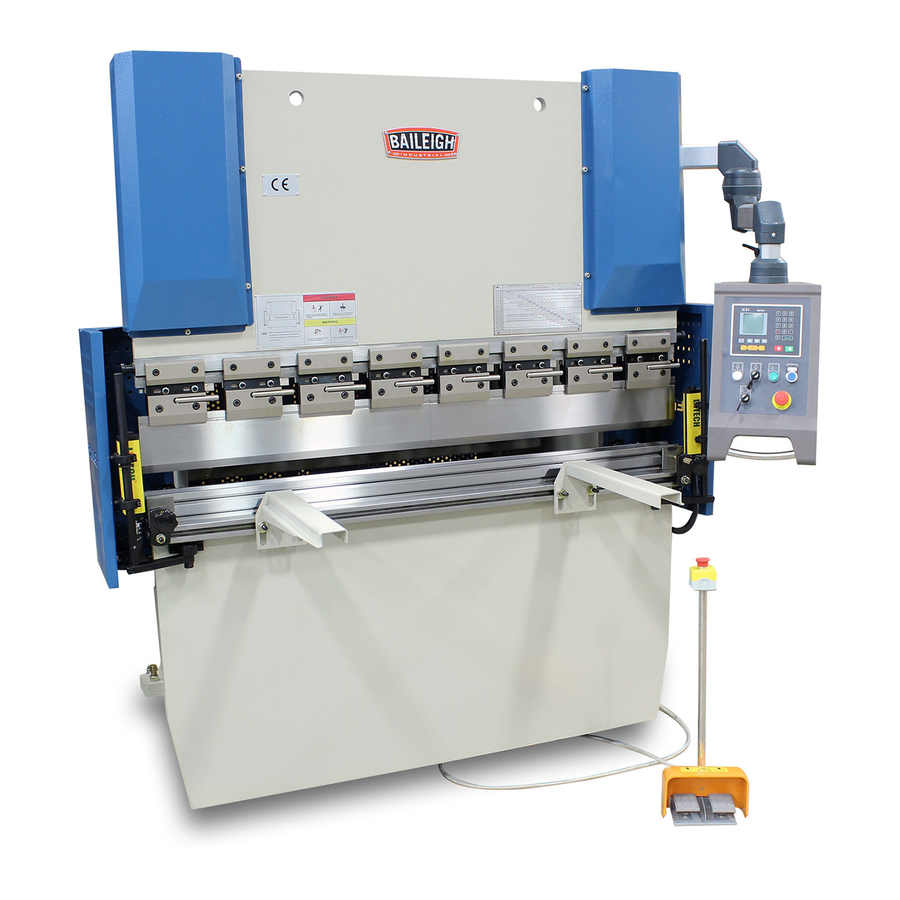
HYDRAULIC PRESS BRAKE
MODEL: BP-3305CNC
Baileigh Industrial Holdings LLC
P.O. Box 531
Manitowoc, WI 54221-0531
Phone: 920.684.4990
Fax: 920.684.3944
sales@baileigh.com
REPRODUCTION OF THIS MANUAL IN ANY FORM WITHOUT WRITTEN APPROVAL OF BAILEIGH INDUSTRIAL
HOLDINGS LLC IS PROHIBITED. Baileigh Industrial Holdings LLC, Inc. does not assume and hereby disclaims any
liability for any damage or loss caused by an omission or error in this Operator's Manual, resulting from accident,
negligence, or other occurrence.
Rev. 07/2019
© 2019 Baileigh Industrial Holdings LLC
Advertisement
Table of Contents

Related Manuals for Baileigh Industrial BP-3305CNC


Summary of Contents for Baileigh Industrial BP-3305CNC
- Page 1 REPRODUCTION OF THIS MANUAL IN ANY FORM WITHOUT WRITTEN APPROVAL OF BAILEIGH INDUSTRIAL HOLDINGS LLC IS PROHIBITED. Baileigh Industrial Holdings LLC, Inc. does not assume and hereby disclaims any liability for any damage or loss caused by an omission or error in this Operator’s Manual, resulting from accident, negligence, or other occurrence.
-
Page 2: Table Of Contents
Table of Contents THANK YOU & WARRANTY ..................1 INTRODUCTION ......................3 GENERAL NOTES ......................3 SAFETY INSTRUCTIONS ....................4 SAFETY PRECAUTIONS ....................7 Dear Valued Customer: ....................7 TECHNICAL SPECIFICATIONS ..................9 TECHNICAL SUPPORT ....................9 UNPACKING AND CHECKING CONTENTS ..............10 TRANSPORTING AND LIFTING .................. - Page 3 Back Gauge Adjustment .................... 48 BEND TONNAGE CHART .................... 50...
-
Page 4: Thank You & Warranty
THANK YOU & WARRANTY Thank you for your purchase of a machine from Baileigh Industrial Holdings LLC. We hope that you find it productive and useful to you for a long time to come. Inspection & Acceptance. Buyer shall inspect all Goods within ten (10) days after receipt thereof. Buyer’s payment shall constitute final acceptance of the Goods and shall act as a waiver of the Buyer’s rights to inspect or... - Page 5 We apologize for any discrepancies that may occur. Baileigh Industrial Holdings LLC reserves the right to make any and all changes deemed necessary in the course of business including but not limited to pricing, product specifications, quantities, and product availability.
-
Page 6: Introduction
INTRODUCTION The quality and reliability of the components assembled on a Baileigh Industrial Holdings LLC machine guarantee near perfect functioning, free from problems, even under the most demanding working conditions. However, if a situation arises, refer to the manual first. If a solution cannot be found, contact the distributor where you purchased our product. -
Page 7: Safety Instructions
IMPORTANT PLEASE READ THIS OPERATORS MANUAL CAREFULLY It contains important safety information, instructions, and necessary operating procedures. The continual observance of these procedures will help increase your production and extend the life of the equipment. SAFETY INSTRUCTIONS LEARN TO RECOGNIZE SAFETY INFORMATION This is the safety alert symbol. - Page 8 SAVE THESE INSTRUCTIONS. Refer to them often and use them to instruct others. PROTECT EYES Wear safety glasses or suitable eye protection when working on or around machinery. PROTECT AGAINST NOISE Prolonged exposure to loud noise can cause impairment or loss of hearing.
- Page 9 HYDRAULIC HOSE FAILURE Exercise CAUTION around hydraulic hoses in case of a hose or fitting failure. BEWARE OF PINCH POINTS Keep hands and fingers away from the servo motors drive belt and pulleys when performing maintenance. Keep motor guards in place at all times while the machine is running.
-
Page 10: Safety Precautions
SAFETY PRECAUTIONS Metal working can be dangerous if safe and proper operating procedures are not followed. As with all machinery, there are certain hazards involved with the operation of the product. Using the machine with respect and caution will considerably lessen the possibility of personal injury. However, if normal safety precautions are overlooked or ignored, personal injury to the operator may result. - Page 11 8. Do not force tool. Your machine will do a better and safer job if used as intended. DO NOT use inappropriate attachments in an attempt to exceed the machine’s rated capacity. 9. Use the right tool for the job. DO NOT attempt to force a small tool or attachment to do the work of a large industrial tool.
-
Page 12: Technical Specifications
TECHNICAL SPECIFICATIONS 63" x 7” (1600 x 176mm) Table Length x Width 21.5” (546mm) Back Gauge Length Maximum Pressure 33 tons (29.9metric tons) Throat Depth 7.87" (200mm) Distance Between Housings 51.3" (1304mm) Distance From Table To Ram 11.8" (300mm) Stroke Distance 3.9"... -
Page 13: Unpacking And Checking Contents
UNPACKING AND CHECKING CONTENTS Your Baileigh machine is shipped complete. Separate all parts from the packing material and check each item carefully. Make certain all items are accounted for before discarding any packing material. WARNING: SUFFOCATION HAZARD! Immediately discard any plastic bags and packing materials to eliminate choking and suffocation hazards to children and animals. -
Page 14: Transporting And Lifting
TRANSPORTING AND LIFTING CAUTION: Lifting and carrying operations should be carried out by skilled workers, such as a truck operator, crane operator, etc. If a crane is used to lift the machine, attach the lifting chain carefully, making sure the machine is well balanced. -
Page 15: Installation
• Level the machine so that all the supporting feet are taking the weight of the machine and no rocking is taking place. INSTALLATION IMPORTANT: Consider the following when looking for a suitable location to place the machine: • Overall weight of the machine. •... -
Page 16: Anchoring The Machine
• FLOOR: This machine distributes a large amount of weight over a small area. Make certain that the floor is capable of supporting the weight of the machine, work stock, and the operator. The floor should also be a level surface. If the unit wobbles or rocks once in place, be sure to eliminate by using shims. -
Page 18: Assembly
Assembly Front Support The front support arms install on the front face of the worktable. The support can mount in any position along the front T-slot. The support can be raised or lowered to align with the lower die as needed. Foot Pedal Connection Position the foot pedal and route the cable to the electrical enclosure in a manner that will allow easy access during... -
Page 19: Electrical
3-phase power source other than direct 3-phase. If you are using an alternate power source, consult a certified electrician or contact Baileigh Industrial Holdings LLC prior to energizing the machine. CAUTION: HAVE ELECTRICAL UTILITIES CONNECTED TO MACHINE BY A CERTIFIED ELECTRICIAN! Check if the available power supply is the same as listed on the machine nameplate. -
Page 20: Power Cord Connection
WARNING: In all cases, make certain the receptacle in question is properly grounded. If you are not sure, have a qualified electrician check the receptacle • Improper connection of the equipment-grounding conductor can result in risk of electric shock. The conductor with insulation having an outer surface that is green with or without yellow stripes is the equipment-grounding conductor. -
Page 21: Getting To Know Your Machine
GETTING TO KNOW YOUR MACHINE... - Page 23 Item Description Bending Cylinders. Moves the ram, (Y Axis) down and up. Internal stops are used to set the depth of bend. Upper Ram Plate. Holds the bending punch and moves down to press the punch into the material and then the die to create the form of the punch and die set. Control Pendent Swing Arm.
-
Page 24: Switch And Button Functions
Back Gauge Motor (X Axis). This motor is used to change the position of the back- gauge support arm. This changes how far in the material is positioned before the bend. The back gauge and the material stops may be manually adjusted as needed by the operator for the specific bend desired. -
Page 25: E21 Controller
CYCLE MODE SELECTOR SWITCH – The Cycle Mode Selector switch (E) is a 2-position switch which allows you to pick one of two bend modes. • In the left “inch” mode, the die will move down or up when the foot pedal is pressed and stop when the foot pedal is released. - Page 26 Start/Run, To let the controller operate. The LED in the corner will illuminate when running. Interface switching, mainly used to switch among parameter interface, programming interface and diagnose interface and to modify in program sequence. Left Direction key, moves the cursor to the left or page back. Right Direction key, moves the cursor right or page forward.
-
Page 27: Safety Equipment
High/low speed selection, Press the corresponding double plus or double minus key along with the slow speed key to double the travel speed for the axis that is highlighted on the Single screen. Safety Equipment WARNING: This section describes the safety equipment installed on this machine so that the operator is aware of how it functions. -
Page 28: Machine Operation
MACHINE OPERATION CAUTION: Always wear proper eye protection with side shields, safety footwear, and leather gloves to protect from burrs and sharp edges. When handling large heavy materials make sure they are properly supported. Keep hands and fingers clear of the bending dies. Stand off to the side of the machine to avoid getting hit with the work material while the punch is pressing the material into the bending die. - Page 29 For the first time testing, select “INCH” mode to test the machine actions, and then test “Semi- Auto” mode and the ram stroke adjustment, the back-gauge control etc. Only when the machine actions are confirmed to be completely correctly, operation can be done as per the following procedures: 1.
- Page 30 6. Define the lower limit position of the rams. This is the YP value. 7. Adjust the limit switch ramps for the travel limit switches so that the distance between the upper die and lower die is only slightly more than the thickness of the material being run. Doing so will reduce the chance of a foreign object getting between the dies and provide a faster cycle time when doing production work.
-
Page 31: Programming
PROGRAMMING This device has two programming methods, which are single-step programming and multi-step programming. The user can set up programming according to actual demand. At start up, the control screen will display the “Single” mode programing screen. Pressing the key will toggle between the three main programming screens. The Single screen may be programmed directly to complete a single... -
Page 32: Bending Operation
Bending Operation NOTICE: This machine is designed for balanced operation. That means that the material should be evenly positioned between the dies from the center out. Loading material on one end of the machine will cause excessive loading on one ram and slide. This will shorten the life of the components and possibly damage the machine frame beyond repair. - Page 33 This value is the programmed piece count desired for the job to be run. This value is a value that shows number of bends completed. The bottom line of the screen (pencil symbol) will display the parameter limits when the parameter is highlighted. When a value is entered, that value will display until the Enter key or Cancel key is pressed.
- Page 34 7. Press the Enter key. This will enter the value into the YP line and move the highlight to the next line. The DX line. 8. Enter the value desired for the back-gauge to retract away from the work piece (DX). 0 (zero) will keep the back gauge in position for the entire bend.
- Page 35 17. Press the Enter key. This will enter the value into the CP line and move the highlight to the next line. The XP line. 18. Place the Mode key switch in the semi-auto (right) position. 19. Press the Start/Run key to enter the operational page.
-
Page 36: Multi-Step Programming
Multi-Step Programming Multi-step program is used for processing single work piece of different processing steps, realize consecutive implementation of multi-steps, and improve processing efficiency. The following items may be programmed into the controller on this screen to be used for Multi Stage bending. - Page 37 Multi-Bend Operation Steps 1. Start the press and allow the controller to boot up. 2. Start the hydraulic pump. 3. The “Single” screen will appear with the “XP” line highlighted. 4. Press the button to switch to Program manage screen. 5.
- Page 38 a. The CP line is a bend counter line. If 0 (zero) is entered for the PP value, the CP line will continue to count each bend cycle as one bend. If the PP line has a value, the CP number will count down from the programmed value to 0 (zero) to complete the counted parts.
- Page 39 24. Enter the value desired for the back-gauge to retract away from the work piece (DX). 0 (zero) will keep the back gauge in position for the entire bend. This value will be displayed in the bottom line of the screen. 25.
-
Page 40: Understanding Springback
34. When the die area and work piece swing area are clear, press and hold the Down foot pedal to complete the bend. a. The foot pedal may be released when the ram is lowered enough to engage the down travel limit switch. -
Page 41: Axis Fine Adjustment
• Chemical structure of material must be consistent. • Buy certificated steel from the same vendor when possible. X AXIS FINE ADJUSTMENT WARNING: Entanglement Hazard! Always keep hands and fingers away from the adjustment handwheel when the press is adjusting the X axis automatically. The handwheel spins at a high rate of speed and will injure hands and fingers if contact is made when the handwheel is in motion. -
Page 42: Axis Teach In
X AXIS TEACH IN The X axis teach in is used to calibrate the exact position of the X axis (back gauge) at the specific time it is being measured. This calibration is done by bending a piece of material and then measuring the length of the material from the edge of the material that contacted the stop fingers to the bend radius. -
Page 43: Y Axis Teach In
Y AXIS TEACH IN The Y axis teach in is used to calibrate the relative position of the Y axis (bending ram) at the specific time it is being measured. This is not a common adjustment to be performed. This calibration is done by placing a piece of paper on the top of the die and then lowering the ram so that the bottom of the punch just touches the paper on the top of the die without bending the paper. -
Page 44: Included Lower And Upper Tooling
INCLUDED LOWER AND UPPER TOOLING Lower Tool (Die) Upper Tool (Punch) -
Page 45: Changing And Adjusting Dies
CHANGING AND ADJUSTING DIES Rotating Lower Die WARNING: Always keep hands and fingers from between the dies. The dies supplied with the press are heavy. Have an assistant and a suitable lifting device available. DO NOT try and remove by yourself. Note: Never install or use dies that are cracked, chipped, or otherwise damaged. -
Page 46: Replacing Lower Die
Replacing Lower Die WARNING: Always keep hands and fingers from between the dies. The dies supplied with the press are heavy. Have an assistant and a suitable lifting device available. DO NOT try and remove by yourself. Note: Never install or use dies that are cracked, chipped, or otherwise damaged. Make sure dies are the correct size and type to reduce the risk of overload. -
Page 47: Replacing Upper Die
Replacing Upper Die The upper die is a two piece design which allows each half to be slid out the side of the press table area. The quick change handles allow for fast tooling changes. WARNING: Always keep hands and fingers from between the dies. The dies supplied with the press are heavy. -
Page 48: Adjusting Upper Die
Adjusting Upper Die The upper die is a two piece design with each section held in position by four mounting block. Each mounting block uses a wedge block to allow for alignment of the two die sections as well as making the upper die set parallel to the lower die. WARNING: Always keep hands and fingers from between the dies. -
Page 49: Machine Adjustment
MACHINE ADJUSTMENT Ram Stroke Limit Switch Adjustment The ram travel is controlled by four different switch/control groups. • The E21 Controller has depth of and mode of operation, travel settings, and time delays for travel. • The Foot Pedals signal to start and stop up and down motion. •... -
Page 50: Up Stroke
NOTICE: DO NOT allow the contact blocks to be adjusted so that the switch roller is able to get positioned on the back (square) end of the block. Because there is no ramp, the roller and the switch will be damaged. This is NOT covered by warranty. Up Stroke When the ram raises, the ram will stop at the position in which the up contact block triggers the up stroke... - Page 51 2. Firmly tighten the thumb screw. Back Gauge Adjustment Along with the adjustment of the back gauge via the CNC controller the back gauge can be adjusted manually for height, and width. This is used to fine tune the back gauge setting and/or adapt the stops to the specific application.
- Page 52 Stop Block Adjustment Typically, this adjustment is to fine tune the stop block for squaring and accuracy, however, within the limits of the adjustment slots, this may also be used to create small angles between the stop blocks and the bending center line. This may be useful in creating a slight conning effect to the work material.
- Page 53 BEND TONNAGE CHART Select the V-Die opening that matches the needed bend type and remains within the press operating tonnage. The opening choices are .31, .39, .47, 5/8, .94, 1-1/4, 2" (8, 10, 12, 16, 24, 32, 50mm)
- Page 54 NOTES...
- Page 55 NOTES...
- Page 56 BAILEIGH INDUSTRIAL HOLDINGS LLC 1625 D , WI 54220 UFEK RIVE ANITOWOC : 920. 684. 4990 F : 920. 684. 3944 HONE www.baileigh.com BAILEIGH INDUSTRIAL HOLDINGS LTD. U WIFT OINT WIFT ALLEY NDUSTRIAL STATE UGBY , CV21 1QH U IDLANDS...
Need help?
Do you have a question about the BP-3305CNC and is the answer not in the manual?
Questions and answers