Table of Contents
Advertisement
Quick Links
Download this manual
See also:
User Manual
Advertisement
Table of Contents

Related Manuals for Adaptec DURASTOR 6320SS


Summary of Contents for Adaptec DURASTOR 6320SS
- Page 1 NSTALLATION AND UIDE 412R/6320SS/7320SS...
- Page 2 Copyright ©2002 Adaptec, Inc. All rights reserved. No part of this publication may be reproduced, stored in a retrieval system, or transmitted in any form or by any means, electronic, mechanical, photocopying, recording or otherwise, without the prior written consent of Adaptec, Inc., 691 South Milpitas Blvd., Milpitas, CA 95035.
- Page 3 Regulatory Compliance Statements Federal Communications Commission Radio Frequency Interference Statement WARNING: Changes or modifications to this unit not expressly approved by the party responsible for compliance could void the user’s authority to operate the equipment. This equipment has been tested and found to comply with the limits for a Class A digital device, pursuant to Part 15 of the FCC rules.
-
Page 4: Table Of Contents
Turning the Power Off 2-7 Configuring DuraStor 2-8 Basic Configuration – DuraStor 412R 2-8 Basic Configuration – DuraStor 6320SS 2-12 Basic Configuration – DuraStor 7320SS 2-13 Cabling Your Storage System to the Host 2-15 Basic Connections – DuraStor 6320SS 2-15 Basic Connections –... - Page 5 Enclosure SAF-TE Monitoring 4-9 Uploading SAF-TE Controller Card Firmware 4-11 Understanding and Maintaining Components Front Bezel 5-2 RAID Controllers (6320SS and 7320SS only) 5-3 Replacing a RAID Controller 5-4 Replacing a “Killed” Controller 5-5 Upgrading the Memory Module 5-6 Replacing the Battery 5-7...
- Page 6 Errors 6-15 Disk Errors 6-16 Disk Channel Errors 6-17 Theory of Controller Operation Operating Modes Overview A-2 Operating Modes – DuraStor 6320SS A-4 Stand-Alone Mode A-4 Active-Active Mode A-7 Active-Passive Mode A-11 Operating Modes – DuraStor 7320SS A-14 Stand-Alone Mode A-14...
- Page 7 DuraStor 412R/6320SS/7320SS Installation and User’s Guide Hubs Disabled (Single External Hub) B-9 Hubs Enabled B-10 SAN Configuration Not Supported B-11 True LUN Sharing B-11 Advanced Configurations and Cabling Advanced Configurations – DuraStor 412R C-1 JBOD – 24-Drive Configuration C-1 Advanced Configurations – DuraStor 6320SS C-4 RAID –...
- Page 8 VHDCI SCSI Connectors D-2 RS-232 Service Ports D-5 Null-Modem Cable D-6 Technical Specifications DuraStor 412R Drive Enclosure E-2 DuraStor 6320SS Storage Subsystem E-3 DuraStor 6200S External RAID Controller E-4 DuraStor 7320SS Storage Subsystem E-6 DuraStor 7200S External RAID Controller E-7 Glossary...
-
Page 9: Introduction
About This Guide This Installation and User’s Guide describes how to install, use, and maintain these Adaptec DuraStor products: DuraStor 412R drive enclosure DuraStor 6320SS SCSI-to-SCSI external RAID storage subsystem DuraStor 7320SS Fibre Channel-to-SCSI external RAID storage subsystem This Guide does not describe the two storage management software tools provided as part of the complete DuraStor package. -
Page 10: Overview
DuraStor 412R/6320SS/7320SS Installation and User’s Guide Overview DuraStor 412R Figure 1-1 shows the components of the DuraStor 412R drive enclosure. 350-watt hot-pluggable independent power supplies Dual in-line 80-CFM hot swappable cooling fans SAFTE Disk I/O Card SAF-TE Service & VT-100 Ports... -
Page 11: Durastor 6320Ss
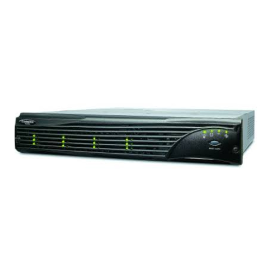
DuraStor 6320SS Figure 1-2 shows the components of the DuraStor 6320SS Storage Subsystem. 350-watt hot-pluggable independent power supplies Dual in-line 80-CFM hot swappable cooling fans SAFTE Disk I/O Card I/O Card (SCSI) Host I/O Card SAF-TE Service & VT-100 Ports... -
Page 12: Durastor 7320Ss
DuraStor 412R/6320SS/7320SS Installation and User’s Guide DuraStor 7320SS Figure 1-3 shows the components of the DuraStor 7320SS Storage Subsystem. 350-watt hot-pluggable independent power supplies Dual in-line 80-CFM hot swappable cooling fans SAFTE Disk I/O Card I/O Card (SCSI) Host I/O Card SAF-TE Service &... -
Page 13: About The Storage Management Software Tools
RS-232 serial port connection on the rear panel of the DuraStor RAID appliance. See on page 3-4 for detailed instructions. You can find the Adaptec Disk Array Administrator User’s Guide on the DuraStor CD. for details. Accessing Disk Array Administrator... -
Page 14: Setting Up Your Storage Subsystem
Configuring DuraStor Cabling Your Storage System to the Host Upgrading DuraStor This chapter explains how to set up the DuraStor 6320SS and 7320SS storage subsystems. Unless otherwise noted, the installation instructions apply to both storage subsystems. For a smooth and trouble-free installation, thoroughly review this chapter and perform the procedures in the order in which they are presented. -
Page 15: Installation Overview
DuraStor 412R/6320SS/7320SS Installation and User’s Guide Installation Overview The installation procedures are divided into three main tasks: 1 Installing your storage subsystem into a rack cabinet 2 Configuring your storage subsystem setting SAF-TE Disk I/O card switches and completing subsystem-to-subsystem cabling. - Page 16 2 Unlock the front bezel by turning the screws one-quarter turn to the left. See Figure Figure 2-1 Unlocking the Front Bezel 3 Using both hands, pull the front bezel from the storage subsystem. See Figure Figure 2-2 Removing the Front Bezel Setting Up Your Storage Subsystem 2-1.
- Page 17 DuraStor 412R/6320SS/7320SS Installation and User’s Guide 4 Select a location within your rack. If you are installing more than one storage subsystem, consider the location of the first one in relation to the others to ensure that there will be adequate airflow and that the cables can be easily reached.
- Page 18 9 Slide one of the rack’s mounting rails into the slot on the left side of the RAID appliance’s back panel. See Push the rail in until it fits the depth of the rack. The rail should mate with mounting slots on the rack’s rear vertical member and make the appliance level and tight-fitting.
-
Page 19: Connecting The Power Cords
DuraStor 412R/6320SS/7320SS Installation and User’s Guide 13 Install the disk drives. See instructions on attaching drive carriers to disk drives and installing disk drives into the storage subsystem. 14 Replace the front bezel. Ensure that it mounts to the two posts and that the bezel lip fits under the chassis top. -
Page 20: Powering On And Powering Off
Powering On and Powering Off Note: Before turning on the power, ensure that none of the data cables or power cables are obstructing the airflow to the cooling fan modules. Turning the Power On 1 Locate the PSUs’ subsystem. 2 Turn each PSU. -
Page 21: Configuring Durastor
DuraStor 412R/6320SS/7320SS Installation and User’s Guide Configuring DuraStor Note: This section provides configuration information for basic 12-disk drive systems. For more advanced configuration information, see Cabling. Configure your storage subsystem by setting the switches and jumpers and connecting the data cables. Follow the instructions... - Page 22 Note: In these logical view diagrams, the numbers 1 to 12 represent disk drive slots and are used to indicate which drives are connected to which channel. They should not be confused with the disk drive SCSI IDs. Those IDs are pre- determined by the SCSI disk I/O card switch settings.
- Page 23 DuraStor 412R/6320SS/7320SS Installation and User’s Guide 3 Locate the switches on the card and set them as shown in figures through 2-10. Some configurations have multiple switch setting options available. Choose the setting that is appropriate for your system. There is one switch setting for single-bus mode and two possible settings for dual-bus mode.
- Page 24 5 (Single-Bus Mode installations only) Install the single-bus module in the Controller 1 slot. (See Cover Plate on page 5-9 6 Connect the SCSI data cable from the host system HBA to the SAF-TE Disk I/O card Channel connector as shown in Figure 2-12.
-
Page 25: Basic Configuration - Durastor 6320Ss
DuraStor 412R/6320SS/7320SS Installation and User’s Guide Basic Configuration – DuraStor 6320SS The DuraStor 6320SS can be set up to provide a storage solution with up to 12 disk drives. This configuration uses the primary RAID enclosure only. If you need to use more disk drives, you can add up to two additional 412R drive enclosures to the DuraStor 6320SS storage subsystem. -
Page 26: Basic Configuration - Durastor 7320Ss
RAID Controllers = 6 & 7 Switch Settings UP (1) DOWN (0) Figure 2-14 Dual-Bus Switch Setting – Option 2 (DuraStor 6320SS) 4 Reinstall the SAF-TE disk I/O card. See page 5-21 for detailed instructions. The configuration is complete. Refer to the Storage Manager Pro User’s Guide or the Disk Array Administrator User’s Guide for... - Page 27 DuraStor 412R/6320SS/7320SS Installation and User’s Guide There are two possible switch settings for this configuration. You may choose either setting to fit your needs. SAF-TE ID = 8/8 RAID Controllers = (6 & 7) Switch Settings UP (1) DOWN (0) Figure 2-15 Dual-Bus Switch Setting –...
-
Page 28: Cabling Your Storage System To The Host
See Controller Operation for descriptions of each operating mode. Follow the instructions provided for your storage subsystem: For the DuraStor 6320SS, see the next section – DuraStor 6320SS). For the DuraStor 7320SS, see DuraStor 7320SS on page Basic Connections –... - Page 29 DuraStor 412R/6320SS/7320SS Installation and User’s Guide 4 Power your storage subsystem. See page 2-7 for instructions. 5 Once everything is powered operating mode. By default, the RAID controller’s operating mode is set to active-active single-port. Use Storage Manager Pro or Disk Array Administrator to change the operating mode.
- Page 30 Connect the SCSI data cables as shown in Termination Termination Figure 2-17 Logical Diagram – Stand-Alone Single-Port Figure 2-18 Host Cabling Diagram – Single Host, Single HBA Setting Up Your Storage Subsystem Figure 2-17 Figure Termination Termination Termination 2-18. 2-17...
- Page 31 DuraStor 412R/6320SS/7320SS Installation and User’s Guide Stand-Alone Dual-Port: Host Cabling Choose this topology when your application requires a low-cost high-performance, fault-tolerant disk storage solution with multiple paths to storage. This solution provides a single controller configuration that supports multiple or dual ported access to one or more host system computers.
- Page 32 Active-Active Single-Port: Host Cabling Choose this topology when your application requires a high- performance, robust, full system-level fault-tolerant disk storage solution and transparent controller failover/failback. This dual controller configuration supports a host with a single-port HBA and is ideal when the host driver software does not support LUNs that appear twice.
- Page 33 DuraStor 412R/6320SS/7320SS Installation and User’s Guide Active-Passive Dual-Port: Host Cabling Choose this topology when your application requires a high- performance, robust, full system-level fault-tolerant disk storage solution. This dual controller configuration supports multiple hosts and failover and failback operations. All LUNs are available to all hosts.
-
Page 34: Basic Connections - Durastor 7320Ss
Basic Connections – DuraStor 7320SS Note: This section provides cabling information for basic topologies. For more advanced topology information, see Appendix C, Advanced Configurations and Appendix A, Theory of Controller Operation each operating mode. 1 Install your host bus adapter(s) into the host system(s). Refer to your HBA user’s guide for specific details. - Page 35 DuraStor 412R/6320SS/7320SS Installation and User’s Guide Basic Stand-Alone Dual-Port Topology – DuraStor 7320SS Only Choose a stand-alone dual-port topology when your application requires a low-cost, entry-level, fault-tolerant disk storage solution. This solution provides a single controller configuration that supports dual-ported access with the internal hubs disabled.
- Page 36 Basic Active-Active Single-Port Topology Choose this topology when your application requires a high- performance, robust, full system-level fault-tolerant disk storage solution with transparent controller failover/failback. This dual controller configuration supports a host with a single-port HBA and is ideal when the host driver software does not support LUNs that appear twice.
- Page 37 DuraStor 412R/6320SS/7320SS Installation and User’s Guide Basic Active-Active Dual-Port Topology Choose this topology when your application requires a high- performance, robust, full system-level fault-tolerant disk storage solution. This dual controller configuration supports multiple hosts and failover and failback operations. All LUNs are available to all hosts.
- Page 38 Basic Active-Passive Dual-Port Topology Choose this topology when your application requires a high- availability, high-access, fault-tolerant disk storage solution. This dual controller configuration supports multiple hosts and failover and failback operations. All LUNs are available to all hosts. The dual host configuration is ideal for shared storage clustering. Connect the fibre channel data cables as shown in Figure 2-32.
-
Page 39: Upgrading Durastor
DuraStor 412R/6320SS/7320SS Installation and User’s Guide Upgrading DuraStor You may need to change your storage subsystem from one drive configuration to another or add another RAID controller to expand your storage subsystem capabilities and capacity. The DuraStor RAID controllers features drive roaming. Drive... -
Page 40: Accessing Your Storage Management Tools
Management Tools In this Chapter Installing Storage Manager Pro Accessing Disk Array Administrator Your DuraStor 6320SS or 7320SS includes two different storage management software tools to help you create and manage your external RAID storage subsystems, Storage Manager Disk Array Administrator. -
Page 41: Installing Storage Manager Pro On Windows
You must also delete the old StorageManagerPro directory. To uninstall Storage Manager Pro, refer to the Adaptec Storage Manager Pro User’s Guide. When you install Storage Manager Pro for Windows, you automatically install Java Runtime Environment (JRE) 1.1.8, which... -
Page 42: Installing Storage Manager Pro On Solaris
Storage Manager Pro. The installation is complete. You can now perform all of the functions described in the Adaptec Storage Manager Pro User’s Guide. Warning: Adaptec strongly recommends that you regularly and consistently back up your data so that it may be recovered in the event of a failure that’s not protected by a... -
Page 43: Accessing Disk Array Administrator
DuraStor 412R/6320SS/7320SS Installation and User’s Guide Accessing Disk Array Administrator Disk Array Administrator is firmware built into the DuraStor 6200S/7200S external RAID controller. To access Disk Array Administrator, you need A computer with terminal emulator software, such as HyperTerminal. A null modem cable. (You cannot use a straight-through serial cable.) - Page 44 The initial Disk Array Administrator screen appears. 3 Press Enter. The System Menu screen appears. You can now perform all of the functions described in the Adaptec Disk Array Administrator User’s Guide. Caution: Adaptec recommends that you regularly and consistently back up your data so that it may be recovered in the event of a failure that’s not protected by a fault-tolerant...
-
Page 45: Monitoring Durastor
Monitoring DuraStor In this Chapter Using Front Bezel LEDs Enclosure SAF-TE Monitoring Two features of DuraStor help you monitor your external RAID storage subsystem: Your storage management tool (Storage Manager Pro or Disk Array Administrator) generates events to inform you of errors, failovers, changes to your array configuration, and other functions. -
Page 46: Using Front Bezel Leds
DuraStor 412R/6320SS/7320SS Installation and User’s Guide Using Front Bezel LEDs This section explains the notifications about the enclosure components provided by the front bezel LEDs and the One-Touch Annunciation monitoring system. See the location of the LEDs on the front bezel. -
Page 47: Drive Leds
Monitoring DuraStor Drive LEDs The drive LEDs are located in pairs on the left side of the front bezel in between the ventilation ribs. The drive LEDs consist of drive status LEDs (on the left) and drive activity LEDs (on the right). - Page 48 DuraStor 412R/6320SS/7320SS Installation and User’s Guide Table 4-2 explains how to interpret the drive LEDs. Table 4-2 Drive Status and Activity LEDs Drive Status LED Drive Activity LED Solid green Solid green Flashing green Solid green Solid green Solid green...
-
Page 49: Disk Drive Carrier Lite Pipes
Monitoring DuraStor Disk Drive Carrier Lite Pipes Also, on each disk drive carrier are LitePipes. (See Figure 4-2.) They are located on the lower right side of each disk drive carrier. The LitePipes present some of the information provided by the front bezel drive LEDs, that is, drive activity information and drive fault (failure) or data rebuilding notifications when the front bezel is removed. - Page 50 DuraStor 412R/6320SS/7320SS Installation and User’s Guide To use the One-Touch Annunciation, press and hold the Alarm Reset button. The drive activity LEDs are turned off and the drive status LEDs illuminate in unique combinations to designate certain enclosure conditions. their meanings when using the One-Touch Annunciation.
- Page 51 One-Touch Annunciation Example Figure 4-3 is an example of the switch settings, and the controller and bus configurations when the One-Touch Annunciation is accessed via the Reset button. Note: SAF-TE switches 1 (A0) and 2 (A1) work in combinations to create a specific range of SCSI IDs. SAF-TE Disk I/O Card Switch Settings UP (1)
- Page 52 DuraStor 412R/6320SS/7320SS Installation and User’s Guide Table 4-4 describes the status LEDs for this example. Table 4-4 Drive Status LEDs – One-Touch Annunciation Example Drive Slot Status LED Description Enclosure is in dual-bus mode. SCSI host interface. Switch 1 (A0) is in the DOWN position. This sets the drive SCSI IDs of the slots to IDs 1, 2, 3, 4, 5, 6, 9, 10, 11, 12, 13, 14.
-
Page 53: Enclosure Saf-Te Monitoring
Enclosure SAF-TE Monitoring Another feature of DuraStor is the enclosure monitoring capabilities. The firmware-based monitoring program allows users to view storage system component status and information about the firmware. You may access this program by connecting a VT-100 terminal to the SAF-TE Service port. To access the monitoring program: 1 Connect one end of the null-modem RS-232 cable to the SAF-TE Service port located on the rear panel of the enclosure. - Page 54 DuraStor 412R/6320SS/7320SS Installation and User’s Guide 5 At the prompt, press Ctrl+E. The Enclosure Terminal Utility menu appears. Figure 4-5 Enclosure Terminal Utility Screen 6 To monitor the enclosure components, select option 1, Show Enclosure Environment Status, by pressing the 1 key.
-
Page 55: Uploading Saf-Te Controller Card Firmware
7 Press Esc to return to the Main menu. Note: Options 2 through 4 are factory and technical support features. Do not access these features unless instructed to do so by a support technician. Uploading SAF-TE Controller Card Firmware The following information describes the procedures to upload new firmware to the SAF-TE controller card. - Page 56 DuraStor 412R/6320SS/7320SS Installation and User’s Guide 6 Press 5 to select Firmware Upload. Figure 4-7 Firmware Upload Screen 7 Press the u key (lower case) to start the upload. Using the mouse, click on the pull-down menu Transfers and select Send.
- Page 57 Monitoring DuraStor unused EEPROM space until completed, then copies the new firmware code to the EEPROM active region. If you elect to stop an upload progress, make sure that the stop (abort) command was completed by typing <Control-X> at the prompt. Figure 4-9 Xmodem File Send Dialog Box 9 After the upload is complete, the Upload Program then updates the second SAF-TE processor.
- Page 58 DuraStor 412R/6320SS/7320SS Installation and User’s Guide At 100 percent, the following screen appears. Figure 4-11 Update Confirmation Screen After the confirmation is complete, the following screen appears. Figure 4-12 Update Status Screen 10 Verify that the new firmware has successfully loaded. Press Ctrl+E.
- Page 59 Understanding and Maintaining Components In this Chapter Front Bezel RAID Controllers (6320SS and 7320SS only) Upgrading the Memory Module Replacing the Battery Configuring a Single-Bus Module Disk Drives Power Supply Units Cooling Fan Module SAF-TE Disk I/O Card SCSI I/O Card...
-
Page 60: Front Bezel
DuraStor 412R/6320SS/7320SS Installation and User’s Guide Front Bezel The front bezel (Figure 5-1) houses the status LEDs, drive LEDs, and alarm reset button. When the front bezel is removed, you can access the disk drives. The front bezel can be installed or removed without interruption to current system activities. -
Page 61: Raid Controllers (6320Ss And 7320Ss Only)
Understanding and Maintaining Components RAID Controllers (6320SS and 7320SS only) The 6320SS and 7320SS storage subsystems house one or two RAID controllers. The subsystems provide configurations for single stand-alone and dual active-active/active-passive controller solutions. In the stand-alone mode, the controller operates autonomously. In the active-active/active-passive mode, the two controllers operate as a pair. -
Page 62: Replacing A Raid Controller
DuraStor 412R/6320SS/7320SS Installation and User’s Guide Replacing a RAID Controller Note: The RAID controller is hot-swappable. 1 Identify and locate the failed controller. See Troubleshooting. Controller 1 is the lower controller and Controller 2 is the upper controller, as shown in... -
Page 63: Replacing A "Killed" Controller
6 Using one of the storage management tools (see that the replacement RAID controller has the correct firmware. Note: Active-active and active-passive dual-controllers require the same version of firmware on both controllers. 7 (Active-Active Mode only.) Using one of the storage management tools (see page 1-5), relinquish the partner controller. -
Page 64: Upgrading The Memory Module
DuraStor 412R/6320SS/7320SS Installation and User’s Guide Upgrading the Memory Module 1 Use your screwdriver to loosen and remove the screws that secure the top of the canister to the bottom. There are four screws on each side of the canister and two on the bottom—10 screws in total. -
Page 65: Replacing The Battery
Replacing the Battery 1 Use your screwdriver to loosen and remove the screws that secure the top of the canister to the bottom. There are four screws on each side of the canister and two on the bottom—10 screws in total. 2 Pull the top of the canister away from the bottom, and set it aside. -
Page 66: Configuring A Single-Bus Module
DuraStor 412R/6320SS/7320SS Installation and User’s Guide Configuring a Single-Bus Module The DuraStor 412R drive enclosure can be configured to provide a continuous single SCSI bus when you need to address all of the disk drives on one SCSI bus. To set up the storage subsystem as a single-bus, you need to install the single-bus module, which is available as a separate item from Adaptec. - Page 67 Understanding and Maintaining Components 3 Reinstall the controller cover plate. Single-Bus Module Cover Plate Figure 5-7 Installing the Single Bus Module and Cover Plate...
-
Page 68: Disk Drives
DuraStor 412R/6320SS/7320SS Installation and User’s Guide Disk Drives All models use one-inch-high, 3.5-inch SCSI disk drives. For information on DuraStor-compatible disk drives, go to the Adaptec Web site at www.adaptec.com/go/durastor Attaching a Disk Drive to a Drive Carrier 1 Place the disk drive component-side down on a flat surface, with the SCSI connector facing away from you. - Page 69 3 Grasp the drive carrier handle and pull the disk drive from the storage subsystem, as shown in The tension clips on the drive carrier ensure that the fit is tight. Gentle but firm force may be required to remove the disk drive. Figure 5-8 Removing a Disk Drive 4 Remove the replacement disk drive from its shipping container and remove the anti-static protection packaging.
- Page 70 DuraStor 412R/6320SS/7320SS Installation and User’s Guide 6 Align the drive carrier rail with the grooves in the drive bay. See Figure 5-9. Figure 5-9 Inserting a Disk Drive 7 Push the drive carrier into its bay until it seats completely.
-
Page 71: Power Supply Units
Power Supply Units The DuraStor power system consists of two 350-watt hot- swappable power supply units (PSUs), each with independent AC power and cooling fans. This system provides the storage subsystem with N+1 redundant power. Each PSU has auto- switching circuitry for use with either 110V or 220V AC systems. A PSU is shown in Figure LEDs... -
Page 72: Replacing A Psu
DuraStor 412R/6320SS/7320SS Installation and User’s Guide Replacing a PSU Note: PSUs are hot-swappable. To replace a PSU: 1 Identify the failed PSU and turn it 2 Remove the power cord from the PSU. 3 Using your thumb and fore finger, squeeze the power supply... -
Page 73: Cooling Fan Module
4 Remove the replacement PSU from the shipping container. Inspect the PSU for obvious damage. 5 Slide the new PSU into the open bay until it seats completely and the retaining latch resets. 6 Reconnect the power cord and replace the security bale. 7 Turn the PSU. -
Page 74: Replacing The Cooling Fan Module
DuraStor 412R/6320SS/7320SS Installation and User’s Guide If a fan inside the module fails, the fan status LED remains lit and an alarm sounds. Failed fans must be replaced immediately. Warning: Do not operate the storage subsystem for extended periods of time (greater than 5 minutes) with the cooling fan module removed. -
Page 75: Saf-Te Disk I/O Card
3 Remove the replacement cooling fan module from the shipping container. Inspect the module for obvious damage. 4 Slide the new cooling fan module into the open bay until it seats completely and the retaining latch resets. The fan status LED on the front bezel changes to solid green to indicate normal fan status. - Page 76 DuraStor 412R/6320SS/7320SS Installation and User’s Guide At power-on, the SEPs read the SCSI switch settings and configure the system for the appropriate addresses. The SEPs execute firmware from the onboard flash memory and perform a POST. The firmware is flash upgradeable using the SAF-TE RS-232 service port located below the I/O card slots at the rear of the storage subsystem.
-
Page 77: Scsi I/O Card
When the RAID controllers are installed, the SCSI connectors on the SAF-TE disk I/O card provide the daisy-chain connection to additional DuraStor 412R drive enclosures providing further storage expandability. Note: No external terminators are required. For instructions on removing and replacing the SAF-TE I/O card, Replacing an I/O Card on page SCSI I/O Card Warning: The SCSI I/O card is not hot-swappable. -
Page 78: Fibre Channel Host I/O Card (7320Ss Only)
DuraStor 412R/6320SS/7320SS Installation and User’s Guide require any changes. The default is to have jumpers installed on JP1 and JP2 with JP3 and JP4 unjumpered. For instructions on removing and replacing the SAF-TE I/O card, Replacing an I/O Card on page Fibre Channel Host I/O Card (7320SS only) Warning: The Fibre Channel host I/O card is not hot-swappable. -
Page 79: Replacing An I/O Card
Replacing an I/O Card Warning: The I/O cards are not hot-swappable. You must power down the storage subsystem to remove or replace any I/O card. See Turning the Power Off on page 1 Power off DuraStor. See 2 Identify the faulty I/O card. 3 Disconnect the cables attached to the faulty I/O card. - Page 80 DuraStor 412R/6320SS/7320SS Installation and User’s Guide 9 Align the I/O card with the rail guides of the open bay and push gently but firmly until the card seats completely. The SAF-TE disk I/O card is shown as an example in Figure 5-17 Reinstalling the SAF-TE Disk I/O Card 10 Tighten the thumb screws.
-
Page 81: Optical Sfp Transceiver (7320Ss Only)
Caution: Do not look into the laser light beam for any extended period of time. Dust covers are provided to protect the optical transceivers’ optics. Adaptec highly recommends using the dust covers provided when a connector is not in place. fit into the transceiver. -
Page 82: Rs-232 Ports
DuraStor 412R/6320SS/7320SS Installation and User’s Guide RS-232 Ports Located below the I/O card slots are the SAF-TE service and VT-100 RAID controller RS-232 serial ports. See Figure 5-20 for the location of these ports on the rear panel. Controller 1 VT-100 Port... -
Page 83: Replacing The Storage Subsystem
Replacing the Storage Subsystem If you need to completely replace the DuraStor 6320SS or 7320SS, follow these instructions carefully to remove and replace the storage subsystem safely. Warning: Printed circuit board components are sensitive to electrostatic discharge. To prevent damage, establish a ground... -
Page 84: Installing The New Storage Subsystem
DuraStor 412R/6320SS/7320SS Installation and User’s Guide 9 Remove the I/O cards. See Remove the defective storage subsystem from the rack cabinet. Reverse the installation procedures in Rack on page 2-2. Installing the New Storage Subsystem 1 Install the replacement storage subsystem in the rack cabinet. -
Page 85: Troubleshooting
Troubleshooting In this Chapter General Enclosure Problems Common SCSI Bus Problems Terminal Emulator and COM Port Problems Host SCSI Channel Problems Device SCSI Channel Problems Problems During Bootup Controller Problems Common Problems and Interpreting the LEDs Warning and Error Events Disk Errors Disk Channel Errors This chapter provides typical solutions for problems you may... -
Page 86: General Enclosure Problems
DuraStor 412R/6320SS/7320SS Installation and User’s Guide General Enclosure Problems Symptom Fails to power Cause Power cords are not connected properly. Power not available at the outlet. Power switch not in the proper position. Faulty power cord. Faulty power supply. Solution... -
Page 87: Common Scsi Bus Problems
Common SCSI Bus Problems SCSI Bus problems can usually be attributed to cabling issues or a faulty SAF-TE disk I/O card. Refer to the chart below and review troubleshooting and fault isolation procedures to assist you in identifying the suspect component. Symptom Host SCSI BIOS scan hangs. - Page 88 DuraStor 412R/6320SS/7320SS Installation and User’s Guide Symptom SCSI Bus hangs, SCSI Bus excessively retries, and/or drives drop offline. Probable Cause Faulty connectivity. Faulty SAF-TE disk I/O card (JBOD or daisy- chained enclosure) or host I/O card. Solution Re-check the cable...
- Page 89 Symptom SCSI Bus hangs, (continued). Probable Cause Faulty SAF-TE disk I/O card (JBOD or Daisy-chained enclosure) or host I/O card (continued). Troubleshooting Solution NOTE: A return to a normal condition is indicated by the disk drives coming back online. After the faulty card is replaced, begin re- connecting the data...
-
Page 90: Terminal Emulator And Com Port Problems
DuraStor 412R/6320SS/7320SS Installation and User’s Guide Terminal Emulator and COM Port Problems Symptom Probable Cause Screen displays Baud rate unintelligible mismatch between strings of the terminal characters. emulator and the controller. The default baud rate is 115,200. Solution Follow these steps if you set... - Page 91 Symptom Probable Cause Nothing is Faulty RS-232 cable displayed on connection or the terminal swapped transmit/ emulator receive lines. screen. Screen is Improper setting. updated, but will not respond to keystrokes. Troubleshooting Solution If the cable is properly connected on both ends, try a null modem adapter that will reverse the RS-232 transmit and receive signals.
-
Page 92: Host Scsi Channel Problems
DuraStor 412R/6320SS/7320SS Installation and User’s Guide Host SCSI Channel Problems Symptom The host SCSI BIOS scan displays “Device name not available.” The host SCSI BIOS scan hangs. Only one array is displayed during host SCSI BIOS scan. All arrays are displayed during... -
Page 93: Device Scsi Channel Problems
Device SCSI Channel Problems Symptom Not all disk drives connected to the controller device channels are displayed during boot, or the controller hangs during display of connected drives. Problems During Bootup The following sections describe problems you might encounter during Power On Self-Test (POST) or during bootup sequence of the enclosure and explains how to resolve those problems. - Page 94 DuraStor 412R/6320SS/7320SS Installation and User’s Guide Symptom The system hangs at CT_srv starting. The system hangs during a drive scan. An active-active controller pair hangs during boot up drive scan (typically after displaying CT_Init on the RS-232 display). An active-active controller pair hangs the host system during normal operation or after failing over.
-
Page 95: Controller Problems
Controller Problems Symptom The controller’s STATUS LED is , but there is no RS-232 display. The controller reports a SDRAM memory error. The controller reports a Battery error. Troubleshooting Solution Check that the RS-232 cable is the correct type (null modem). Check that the terminal emulation utility on the computer system is properly... -
Page 96: Common Problems And Interpreting The Leds
DuraStor 412R/6320SS/7320SS Installation and User’s Guide Common Problems and Interpreting the LEDs Symptom Power supply status LED is illuminated. Fan status LED is illuminated. Drive status LED is not illuminated and a disk drive is present in the slot. 6-12... -
Page 97: Warning And Error Events
Warning and Error Events There are a number of conditions that trigger warning or error events, activate the alarm, and may affect the state of the STATUS and FAULT LEDs. The alarm sounds mainly when the software displays a warning or error event. The alarm will silence when you press the Alarm Reset button. - Page 98 DuraStor 412R/6320SS/7320SS Installation and User’s Guide Event SPARE UNUSABLE SMART EVENT ARRAY OFFLINE VOLT/TEMP WARN UNWRITABLE CACHE SDRAM CORR ECC 6-14 Definition The disk drive still contains metadata that must be cleared. A disk drive informational exceptions page control (IEPC)
-
Page 99: Errors
Errors Error events let you know that something related the enclosure, controller, or disk drives has failed and requires immediate attention. The table below defines each error event and recommends the action you should take. Event VOLT/TEMP FAIL ENCLOSURE FAIL BATTERY FAILED DISK CHAN FAILED SDRAM UNCORR... -
Page 100: Disk Errors
DuraStor 412R/6320SS/7320SS Installation and User’s Guide Disk Errors If a disk detects an error, it reports the error and records it in the event log. The following is an example of a disk-detected error. DISK DETECTED ERR 2:05 03,11,0B Disk Channel... -
Page 101: Disk Channel Errors
Disk Channel Errors Disk channel errors are similar to disk-detected errors, except they are detected by the controller, instead of the disk drive. Some disk channel errors are displayed as text strings, others are displayed as hexadecimal values. Figure 6-2 shows a disk channel error displaying the hexadecimal codes. - Page 102 DuraStor 412R/6320SS/7320SS Installation and User’s Guide Table 6-3 Disk Channel Error Codes (Continued) Error Code Description I/O request was aborted because of a channel reset. I/O request was aborted because of controller’s decision to reset the channel. I/O request was aborted because of third-party channel reset (displayed as Abort 3PRST).
-
Page 103: Theory Of Controller Operation
This chapter provides a functional overview and understanding of the supported topologies and operating modes for the DuraStor 6320SS and 7320SS storage subsystems. With this information, you will be able to make the best choice based on the supported topologies, to set up your storage solution. -
Page 104: Operating Modes Overview
DuraStor 412R/6320SS/7320SS Installation and User’s Guide Operating Modes Overview The operating modes let you configure the RAID controllers to support a variety of host environments. Stand-alone single-port—Use this mode when you have a single RAID controller and require single-HBA host access. - Page 105 Note that there are two host ports on each controller (internally). Table A-1 Table A-2 DuraStor 6320SS and 7320SS, respectively. Table A-1 Summary of Operating Modes – DuraStor 6320SS Number of Operating Mode Controllers Stand-Alone...
-
Page 106: Operating Modes - Durastor 6320Ss
Disk Array Administrator. For a detailed discussion of each operating mode, see the section that applies to your DuraStor storage subsystem: For the DuraStor 6320SS, see the next section. For the DuraStor 7320SS, see Operating Modes – DuraStor 6320SS Stand-Alone Mode In stand-alone mode, the RAID controller operates autonomously. - Page 107 Figures through mode. Termination Termination Figure A-1 Stand-Alone, Single-Port, Single Host Host System#1 HBA 1 Termination Host System#2 HBA 1 Termination Figure A-2 Stand-Alone, Single-Port, Two Hosts Theory of Controller Operation show the logical function of this operating Termination Termination Termination Termination Termination...
- Page 108 DuraStor 412R/6320SS/7320SS Installation and User’s Guide Termination Termination Figure A-3 Stand-Alone, Dual-Port, Single Host Termination Termination Figure A-4 Stand-Alone, Dual-Port, Two Hosts Termination Termination Termination Termination Termination Termination...
-
Page 109: Active-Active Mode
Termination Termination Figure A-5 Stand-Alone Dual-Port with Dual Host (Quad Cabling) Active-Active Mode In the active-active mode, the two RAID controllers cooperate to provide redundancy. If one controller fails, the remaining controller will take over the failed controller’s functionality. Each controller has two SCSI host ports, they are labeled in the diagrams as “CH 0”... - Page 110 DuraStor 412R/6320SS/7320SS Installation and User’s Guide Arrays can only be accessed by the controller that currently owns them. One controller will have no visibility to the others’ arrays. If one controller fails, the surviving controller will take ownership of all arrays. Pool spares and unassigned disks are visible to both controllers.
- Page 111 Figure A-6 Figure A-7 controllers when both are active and then again when one controller has failed. Host I/O Host System #1 or Host System #2 HBA#2 Termination Host System #1 HBA#1 Host I/O Termination Figure A-6 Active-Active, Single-Port Mode, Both Controllers Active Host I/O Host System #1 or Host System #2...
- Page 112 DuraStor 412R/6320SS/7320SS Installation and User’s Guide survivor asserts. This is accomplished using Storage Manager Pro or the Disk Array Administrator. If you replace a failed controller with a new controller, the new controller will attempt to retrieve its configuration (see Understanding Mirrored Operations on page surviving controller.
-
Page 113: Active-Passive Mode
Active-Passive Mode In active-passive mode, there is one active and one passive RAID controller. The primary (active) controller operates with both of its host ports enabled and presents all LUNs on both ports to maximize bandwidth. The secondary (passive) controller keeps both of its host ports passive, and does not service any LUNs. - Page 114 DuraStor 412R/6320SS/7320SS Installation and User’s Guide Each controller sends heartbeat messages via the SCSI buses to its partner controller. If a controller does not receive a heartbeat message within a set time period, it will kill the other controller assuming that it has malfunctioned. After killing the other controller, it will take ownership of the arrays and will activate its passive host port to assume the defunct controller’s identity.
- Page 115 Figure A-8 Figure A-9 logical functions when the controllers are functioning in a normal condition and then in a failed condition. Host System #1 or Host System #2 HBA#2 Termination Host System #1 HBA#1 Termination Figure A-8 Active-Passive, Dual-Port, Controller 1 Active Host System #1 or Host System #2 HBA#2...
-
Page 116: Operating Modes - Durastor 7320Ss
DuraStor 412R/6320SS/7320SS Installation and User’s Guide Operating Modes – DuraStor 7320SS Stand-Alone Mode In stand-alone mode, the RAID controller operates autonomously. The controller has two fibre channel (FC) host ports, they are labeled in the diagrams as FC1 and FC2. This operating mode uses both FC host ports. - Page 117 Figure A-10 Figure A-11 operating mode. Controller FC Host Ports HOST I/O T= Location of internal termination Host I/O Connectors Figure A-10 Stand-Alone, Dual-Port, Hubs Disabled Figure A-11 Stand-Alone, Dual-Port, Hubs Enabled depict the logical function of this RAID Controller Drives 7 - 12 Disk Active...
-
Page 118: Active-Active Mode
DuraStor 412R/6320SS/7320SS Installation and User’s Guide Active-Active Mode In the active-active mode, the two RAID controllers cooperate to provide redundancy. If one controller fails, the remaining controller will take over the failed controller’s functionality. Each controller has two fibre channel host ports, they are labeled in the diagrams as FC1 and FC2. - Page 119 Table A-6 Presentation of LUNs in Active-Active Dual-Port Mode Controller Controller 1 Status FC 1 Host Port Both Controller 1 controllers LUNs online Controller 1 Inactive fails Controller 2 Controller 1 fails LUNs In either mode, arrays can only be accessed by the controller that currently owns them.
- Page 120 DuraStor 412R/6320SS/7320SS Installation and User’s Guide Figure A-12 Figure A-15 controllers when both are active and then again when one controller has failed. Controller FC Host Ports RAID Controller HOST I/O Active Passive Controller 1 RAID Controller Host I/O Passive...
- Page 121 Controller FC Host Ports RAID Controller HOST I/O Active Active Controller 1 ACTIVE RAID Controller Host I/O FC1 Active Connectors Active Controller 2 ACTIVE Figure A-14 Active-Active Dual-Port Mode with Hubs Enabled and Both Controllers Active Controller FC Host Ports RAID Controller HOST I/O Active...
- Page 122 DuraStor 412R/6320SS/7320SS Installation and User’s Guide In the failed-over condition, the active controller will present its native identity on one FC host port, and the failed-over controller’s identity on the other port. This is slightly different when using a dual port configuration, where each array is presented on both FC host ports.
-
Page 123: Active-Passive Mode
Disadvantages Host HBA or the Fibre loop are single points of failure. In single host configuration, the host system is also a single point of failure. No upstream fail-over with a single host that has dual HBAs or dual host systems. Protected LUN sharing between two host systems is not supported without the use of third-party file share/file lock software. - Page 124 DuraStor 412R/6320SS/7320SS Installation and User’s Guide Note: The controllers communicate with each other using SCSI initiator IDs 6 and 7 on each of the disk channels. You should not change these IDs. Advantages Transparent fail-over and fail-back. Single point of failure is the host system. (There are no single points of failure when dual host systems are configured with clustering software.)
- Page 125 Figure A-16 Figure A-17 logical functions when the controllers are operating in a normal condition and then in a failed condition. Controller FC Host Ports RAID Controller HOST I/O Active Active Controller 1 ACTIVE RAID Controller Host I/O FC1 Passive Connectors Passive Controller 2...
-
Page 126: Understanding Mirrored Operations
DuraStor 412R/6320SS/7320SS Installation and User’s Guide Understanding Mirrored Operations The mirroring feature causes configuration changes to be mirrored to the opposite controller in an active-active configuration. The mirrored configuration is stored in the other controller’s firmware (Flash). If a controller fails and is replaced, then on boot up, it attempts to retrieve this configuration data from the opposite controller. -
Page 127: Clustering
Note: When Clear Configuration is selected in the Flash Utility menu, both the local Flash configuration and the other controller’s mirrored configuration image are cleared. Also, there is an option (J) in the Flash Utility menu that can be used to tell a booting controller to temporarily ignore the mirrored configuration. - Page 128 DuraStor 412R/6320SS/7320SS Installation and User’s Guide more than 43 hours of downtime per year. In contrast, 99.99 percent uptime translates into less than one hour (52 minutes) of downtime per year. Availability figures relate primarily to unplanned downtime. But the advantages of clusters in terms of planned or scheduled downtime are even more significant.
-
Page 129: How Available Are Clusters
allows for the nodes to be geographically located? How Available are Clusters? Table A-7 outlines the maximum availability per downtime in the different architectures: Table A-7 Maximum Availability Per Downtime Maximum Architecture Availability Continuous 100.00% Processing Fault-Tolerant 99.9999% Clusters 99.9 – 99.999% High 99.9% Availability... - Page 130 DuraStor 412R/6320SS/7320SS Installation and User’s Guide A-28...
-
Page 131: San Solution Strategies (Durastor 7320Ss Only)
SAN Solution Strategies (DuraStor 7320SS only) In this Appendix Active-Active Dual-Port Mode for SAN Active-Active Single-Port Mode for SAN SAN Configuration Not Supported True LUN Sharing This chapter describes connecting the DuraStor 7320SS Storage Subsystems to provide an active-active/active-passive solution to a Storage Area Network (SAN). -
Page 132: Active-Active Dual-Port Mode For San
DuraStor 412R/6320SS/7320SS Installation and User’s Guide Active-Active Dual-Port Mode for SAN At the heart of this strategy is the active-active dual-port operating mode. In this mode, four fibre channel (FC) ports are simultaneously active when both controllers are online. In the event of a controller failure, two FC ports remain available to service all host I/O. -
Page 133: Hubs Enabled
SAN Solution Strategies (DuraStor 7320SS only) Hubs Enabled In Figures and B-2, the controllers are configured in an active- active dual-port mode with the internal hubs enabled. Two hosts are connected via two independent loops using the enclosure’s built-in hub bypass circuits. These circuits provide two internal hubs, eliminating the need for the use of external FC hardware, other than the cables. - Page 134 DuraStor 412R/6320SS/7320SS Installation and User’s Guide Figure B-2 illustrates the conditions when Controller 2 fails. Note that both hosts can still see Controller 1’s LUNs (LUN 1) and Controller 2’s LUNS (LUN 2). However, each host HBA can only see one LUN, instead of both.
-
Page 135: Hubs Disabled
SAN Solution Strategies (DuraStor 7320SS only) Hubs Disabled Figures show two controllers configured in an active- active dual-port mode with the internal hubs disabled. Two hosts are connected via two independent switches. Using external switches supports higher bandwidth, since the host ports are not required to share bandwidth on a loop. - Page 136 DuraStor 412R/6320SS/7320SS Installation and User’s Guide Figure B-4, two hosts are connected via two independent switches. Note that both hosts can still see Controller 1’s LUNs (LUN 1) and Controller 2’s LUNs (LUN 2). However, each host HBA can only see one LUN, instead of both.
-
Page 137: Active-Active Single-Port Mode For San
SAN Solution Strategies (DuraStor 7320SS only) Active-Active Single-Port Mode for SAN In some scenarios, where the host has a single FC port and the SAN is not truly fault-tolerant, it may be desirable to configure the controllers in active-active single-port mode. Hubs Disabled (Single-Port Hosts and One Switch) Figure B-5 shows two single ported hosts connected to the two... - Page 138 DuraStor 412R/6320SS/7320SS Installation and User’s Guide In this case, there would be an advantage to configuring the controllers in active-active dual-port mode, because of increased connectivity. However, the host driver software would need to handle the fact that each LUN would appear twice in the SAN fabric, and that one image of the LUNs would disappear if one controller failed.
-
Page 139: Hubs Disabled (Single External Hub
SAN Solution Strategies (DuraStor 7320SS only) Hubs Disabled (Single External Hub) Figure B-6 shows the hosts in a single loop configuration using an external hub. When a controller failover occurs, this configuration operates much the same as the previous one which uses a switch. The advantage is that a hub is less expensive. -
Page 140: Hubs Enabled
DuraStor 412R/6320SS/7320SS Installation and User’s Guide Hubs Enabled Figure B-7 shows hosts in a single loop configuration with the internal hubs enabled. The internal hubs eliminate the need for an external hub. It allows one or two hosts to be connected to the active-active storage enclosure without the cost of external hardware other than cables. -
Page 141: San Configuration Not Supported
SAN Configuration Not Supported In the active-active dual-port configuration with two independent hubs or the internal hubs, two single-ported hosts is not supported. The issue with this configuration is that if a controller fails, each host loses access to one of the LUNs. For example, if Controller 1 fails, Host 1 can no longer access LUN 2, because Port 2 on Controller 2 has changed from presenting its own LUNs to presenting Controller 1’s LUNs. - Page 142 DuraStor 412R/6320SS/7320SS Installation and User’s Guide The active-active strategy chosen allows a host to access two separate fibre channel ports (one from each controller) which are connected together via a switch or hub, in order to support access to LUNs owned by different controllers. This is simpler and provides higher performance than so-called “true LUN sharing”...
-
Page 143: Advanced Configurations And Cabling
Advanced Configurations and Cabling In this Appendix Advanced Configurations – DuraStor 412R Advanced Configurations – DuraStor 6320SS Advanced Configurations – DuraStor 7320SS Advanced Cabling – DuraStor 6320SS Advanced Cabling – DuraStor 7320SS Advanced Configurations – DuraStor 412R JBOD – 24-Drive Configuration... - Page 144 DuraStor 412R/6320SS/7320SS Installation and User’s Guide Controller 1 slot. This single-bus module connects Channel 1 and Channel 2 together to create a single continuous SCSI bus. Figure C-1 Logical View of Connectivity – Single-Bus Mode Note: In Figure C-1, the drive slots are used to indicate which drives are connected to which channel.
- Page 145 4 Install the single-bus module in the Controller 1 slot in both enclosures. See Installing the Single Bus Module and Cover Plate on page 5-9 for detailed instructions. 5 Connect a SCSI data cable from the host system HBA(s) to the SAF-TE disk I/O card Channel 1 connectors on each enclosure, as shown in Figure...
-
Page 146: Advanced Configurations - Durastor 6320Ss
Advanced Configurations – DuraStor 6320SS RAID – 12-Drive Configuration The DuraStor 6320SS can be setup to provide up to a 12 disk drive storage solution using the primary RAID enclosure only. 1 Remove the SAF-TE disk I/O card installed in both enclosures. -
Page 147: Raid - 24-Drive Configuration
RAID – 24-Drive Configuration The DuraStor 6320SS can be setup to provide up to a 24 disk drive storage solution (12 per channel). 1 Remove the SAF-TE disk I/O card installed in both enclosures. - Page 148 DuraStor 412R/6320SS/7320SS Installation and User’s Guide 4 Remove the SAF-TE disk I/O card installed in the daisy-chain enclosure. See Replacing an I/O Card on page 5-21 instructions. The daisy-chain enclosure will be configured to dual-bus mode. This provides the drive channel expansion from the primary enclosures’...
- Page 149 7 Connect the SCSI data cables from the DuraStor 6320SS to the daisy-chain enclosures’ SAF-TE disk I/O card as shown in Figure C-8. Power Power Supply Supply SCSI Data Cable Power Power Supply Supply Figure C-8 Enclosure Cabling Diagram 8 Connect a SCSI data cable(s) from the host system(s) HBA(s) to the...
-
Page 150: Raid - 36-Drive Configuration
DuraStor 412R/6320SS/7320SS Installation and User’s Guide RAID – 36-Drive Configuration Only the DuraStor 6320SS in the stand-alone single-port mode can be setup in this configuration. It provides up to a 36 disk drive storage solution (12 per channel). This is due to one of the host I/O ports (CH 3) is used as a drive channel to provide the additional connectivity for the second DuraStor 412R drive enclosure. - Page 151 primary enclosures’ disk I/O channels. Set the switches as shown in Figure C-7. SAF-TE ID = 15/15 RAID Controllers = 6 & 7 Switch Settings UP (1) DOWN (0) Figure C-10 Switch Setting – Dual-Bus Daisy-Chain Enclosure 5 Configure the jumper settings on this first daisy-chain enclosure SAF-TE disk I/O card.
- Page 152 DuraStor 412R/6320SS/7320SS Installation and User’s Guide 9 Configure the jumper settings on this second daisy-chain enclosure SAF-TE disk I/O card. Locate and add (installed on both pins) the two jumpers at JP7 and JP8. The default position of the jumpers are offset.
-
Page 153: Advanced Configurations - Durastor 7320Ss
Advanced Configurations – DuraStor 7320SS RAID – 24-Drive Configuration The DuraStor 7320SS can be setup to provide up to a 24 disk drive storage solution. In this configuration you will attach a DuraStor 412R to the primary RAID enclosure which will extend the drive channels (12 drives per channel). - Page 154 DuraStor 412R/6320SS/7320SS Installation and User’s Guide 3 Remove the SAF-TE disk I/O card installed in the daisy-chain enclosure. See Replacing an I/O Card on page 5-21 instructions. The daisy-chain enclosure will be configured to dual-bus mode. This provides the drive channel expansion from the primary enclosures’...
-
Page 155: Raid - 36-Drive Configuration
6 Connect the SCSI data cables from the DuraStor 7320SS disk I/O card to the daisy-chain enclosures’ SAF-TE disk I/O card as shown in Power Power Cooling Supply Supply SCSI Data Cable Power Power Cooling Supply Supply Figure C-15 Enclosure Cabling Diagram 7 Connect a fibre channel data cable(s) from the host system(s) HBA(s) to the host I/O card as indicated in DuraStor 7320SS on page 2-13... - Page 156 DuraStor 412R/6320SS/7320SS Installation and User’s Guide The switch settings assign specific SCSI IDs to the drive slots, as shown in Figure C-13 on page the RAID Controller(s), and IDs 8 or 15 for the SAF-TE processors. 3 Reinstall the SAF-TE disk I/O card in each enclosure. See...
- Page 157 7 Remove the SAF-TE disk I/O card installed in the second daisy- chain enclosure. See instructions. The second daisy-chain enclosure is configured to single-bus mode. It provides the drive channel expansion from the primary enclosures’ I/O card Channel 0. Set the switches as shown in Figure C-17.
-
Page 158: Raid - 48-Drive Configuration
DuraStor 412R/6320SS/7320SS Installation and User’s Guide Note: When connecting the single-bus DuraStor 7320SS enclosure to the primary RAID enclosure, you connect to the Channel 0 connector on the I/O card installed in the primary RAID enclosure. 12 Connect a Fibre Channel data cable(s) from the host system(s) - Page 159 3 Reinstall the SAF-TE Disk I/O card in each enclosure. See Replacing an I/O Card on page 5-21 4 Remove the SAF-TE Disk I/O card installed in the first daisy- chain enclosure. See detailed instructions. The first daisy-chain enclosure will be configured to dual-bus mode.
- Page 160 DuraStor 412R/6320SS/7320SS Installation and User’s Guide switch setting is the same for both of these daisy-chained enclosures. Set the switches as shown in SAF-TE ID = 15 RAID Controllers = 6 & 7 Switch Settings UP (1) DOWN (0) Figure C-20 Switch Setting – Single-Bus Daisy-Chain Enclosure 8 (Second &...
- Page 161 Note: When connecting the single-bus DuraStor 412R drive enclosure to the primary RAID enclosure, you will connect it to the Channel 0 and Channel 1 connectors on the I/O card installed in the primary RAID enclosure. SCSI Data Cable Power Power Cooling Supply...
- Page 162 DuraStor 412R/6320SS/7320SS Installation and User’s Guide 12 Connect a Fibre Channel data cable(s) from the host system(s) HBA(s) to the Host I/O card as indicated in DuraStor 7320SS on page 2-13 on page C-29. The configuration is complete. Refer to the Storage Manager Pro User’s Guide or the Disk Array Administrator User’s Guide for...
-
Page 163: Stand-Alone Single-Port (Dual Hosts, Single Hbas)
Advanced Cabling – DuraStor 6320SS Stand-Alone Single-Port (Dual Hosts, Single HBAs) Connect the SCSI data cables as described Figure C-23. Host System#1 HBA 1 Termination Host System#2 HBA 1 Termination Figure C-22 Logical Diagram – Stand-Alone, Single-Port Figure C-23 Host Cabling Diagram – Dual Host, Single HBAs... -
Page 164: Stand-Alone Dual Port (Dual Hosts, Single Hbas
DuraStor 412R/6320SS/7320SS Installation and User’s Guide Stand-Alone Dual Port (Dual Hosts, Single HBAs) Connect the SCSI data cables as described in Figure C-23. Termination Termination Figure C-24 Logical Diagram – Stand-Alone, Dual-Port Host Computer #1 SCSI Data Cable Power Power... -
Page 165: Stand-Alone Dual Port - Quad Cabling (Two Hbas, Shared Scsi Bus
Stand-Alone Dual Port – Quad Cabling (Two HBAs, Shared SCSI Bus) Connect the SCSI data cables as shown in Figure C-27. Termination Termination Figure C-26 Stand-Alone Dual-Port Logical Diagram Host Computer #1 SCSI Data Cable Power Power Supply Supply Figure C-27 Host Cabling Diagram – Dual Host, Quad Cabling, Two HBAs Advanced Configurations and Cabling Figure C-24 Termination... -
Page 166: Active-Active Single-Port (Single Host, Two Hbas
DuraStor 412R/6320SS/7320SS Installation and User’s Guide Active-Active Single-Port (Single Host, Two HBAs) Connect the SCSI data cables as shown in Figure C-29. HOST I/O CH 0 Host System #1 HBA #1 Termination CH 3 Host System #1 HBA #2 HOST I/O... -
Page 167: Active-Active Single-Port (Dual Host, Single Hbas
Active-Active Single-Port (Dual Host, Single HBAs) Connect the SCSI data cables as shown in Figure C-23. Host System #1 HBA #1 Termination Host System #1 HBA #2 Termination Figure C-30 Logical Diagram – Active-Active Single-Port Figure C-31 Host Cabling Diagram – Dual Host, Single HBAs Advanced Configurations and Cabling Figure C-28 Termination... -
Page 168: Active-Active Single-Port - Quad Cabling (Dual Host, Dual Hbas) #1
DuraStor 412R/6320SS/7320SS Installation and User’s Guide Active-Active Single-Port – Quad Cabling (Dual Host, Dual HBAs) #1 This setup will provide an isolated SCSI bus. Connect the SCSI data cables as shown in Figure C-32 Host System #1 HBA #1 Termination... -
Page 169: Active-Active Single-Port - Quad Cabling (Dual-Host, Dual-Hbas) #2
Active-Active Single-Port – Quad Cabling (Dual-Host, Dual-HBAs) #2 This setup is ideal for clustering configurations. Connect the SCSI data cables as shown in Host System #1 HBA #1 Termination Host System #2 HBA #1 Host System #2 HBA #2 Termination Host System #1 HBA #2 Figure C-34 Logical Diagram –... -
Page 170: Active-Passive Dual-Port (Dual Hosts, Single Hbas
DuraStor 412R/6320SS/7320SS Installation and User’s Guide Active-Passive Dual-Port (Dual Hosts, Single HBAs) Connect the SCSI data cables as shown in Figure C-23. HOST I/O CH 0 Host System #1 HBA #1 Termintation CH 3 Host System #2 HBA #1 HOST I/O... -
Page 171: Advanced Cabling - Durastor 7320Ss
Advanced Cabling – DuraStor 7320SS Stand-Alone Dual-Port (Single Host, Two HBAs, Hubs Disabled) Connect the Fibre Channel data cables as shown in Figure C-39. Controller FC Host Ports HOST I/O Host System #1 HBA 2 Host System #1 HBA 1 Host I/O Connectors Figure C-38 Logical Diagram –... -
Page 172: Stand-Alone Dual-Port (Single Host, Two Hbas, Hubs Enabled
DuraStor 412R/6320SS/7320SS Installation and User’s Guide Stand-Alone Dual-Port (Single Host, Two HBAs, Hubs Enabled) Connect the Fibre Channel data cables as shown in Figure C-41. Controller FC Host Ports HOST I/O Host System #1 HBA 2 Host System #1 HBA 1 Host I/O Connectors Figure C-40 Logical Diagram –... -
Page 173: Stand-Alone Dual-Port (Multiple Hosts, Single Hbas, Hubs Enabled
Stand-Alone Dual-Port (Multiple Hosts, Single HBAs, Hubs Enabled) Connect the Fibre Channel data cables as shown in Figure C-43. Controller FC Host Ports HOST I/O Host System #3 HBA 1 Host System #4 HBA 1 Host System #2 HBA 1 Host System #1 HBA 1 Host I/O Connectors... -
Page 174: Active-Active Single-Port (Single Host, Dual Hbas, Hubs Enabled
DuraStor 412R/6320SS/7320SS Installation and User’s Guide Active-Active Single-Port (Single Host, Dual HBAs, Hubs Enabled) Connect the Fibre Channel data cables as shown in Figure C-45. HOST I/O Host System #1 HBA #2 Host System #1 HBA #1 Host I/O Connectors Figure C-44 Logical Diagram –... -
Page 175: Active-Active Single-Port (Dual Host, Single Hbas, Hubs Enabled
Active-Active Single-Port (Dual Host, Single HBAs, Hubs Enabled) Connect the Fibre Channel data cables as shown in Figure C-51. HOST I/O Host System #1 HBA #1 Host System #2 HBA #1 Host I/O Connectors Figure C-46 Logical Diagram – Dual Host with Single HBAs, Hubs Enabled Host Computer #2 Host Computer #1 Fibre Channel Data Cable... -
Page 176: Active-Active Single-Port (Dual Host, Dual Hbas - Quad Cabling, Hubs Enabled
DuraStor 412R/6320SS/7320SS Installation and User’s Guide Active-Active Single-Port (Dual Host, Dual HBAs – Quad Cabling, Hubs Enabled) Connect the Fibre Channel data cables as shown in Figure C-49. HOST I/O Host System #1 HBA #2 Host System #2 HBA #1... -
Page 177: Active-Passive Dual-Port (Dual Host, Single Hbas, Hubs Enabled
Active-Passive Dual-Port (Dual Host, Single HBAs, Hubs Enabled) Connect the Fibre Channel data cables as shown in Figure C-51. HOST I/O Host System #1 HBA #1 Host System #2 HBA #1 Host I/O Connectors Figure C-50 Logical Diagram – Dual-Host with Single HBAs, Hubs Enabled Host Computer #2 Host Computer #1... - Page 178 DuraStor 412R/6320SS/7320SS Installation and User’s Guide C-36...
-
Page 179: Port Information
Port Information In this Appendix VHDCI SCSI Connectors RS-232 Service Ports Null-Modem Cable This appendix contains detailed information about the very-high- density SCSI connectors on the SAF-TE disk I/O card and host I/O cards. -
Page 180: Vhdci Scsi Connectors
DuraStor 412R/6320SS/7320SS Installation and User’s Guide VHDCI SCSI Connectors On each SAF-TE Disk I/O and host I/O card are two VHDCI SCSI connectors, similar to the one shown in connectors provide the input/output interface from the storage enclosure bus to the host system. - Page 181 Table D-1 VHD/CI Connector Pin Assignment Connector P1 Signal Name Pin Number RESERVED GROUND +ATN GROUND +BSY +ACK +RST +MSG +SEL +C/D +REQ +I/O +DB(8) +DB(9) +DB(10) +DB(11) -DB(12) -DB(13) -DB(14) -DB(15) -DB(P1) -DB(0) -DB(1) -DB(2) -DB(3) -DB(4) -DB(5) -DB(6) -DB(7) -DB(P0) Signal Name...
- Page 182 DuraStor 412R/6320SS/7320SS Installation and User’s Guide Table D-1 VHD/CI Connector Pin Assignment Connector P1 Signal Name Pin Number GROUND GROUND TERMPWR TERMPWR RESERVED GROUND -ATN GROUND -BSY -ACK -RST -MSG -SEL -C/D -REQ -I/O -DB(8) -DB(9) -DB(10) -DB(11) Signal Name...
-
Page 183: Rs-232 Service Ports
Port Information RS-232 Service Ports The RS-232 service ports are located on the back of the storage subsystem. The service port labeled provides a serial SAF-TE interface to the SAF-TE disk I/O card for firmware uploads, maintenance, and service monitoring of the SEPs. Figure D-2 shows the pin signals for this port. -
Page 184: Null-Modem Cable
DuraStor 412R/6320SS/7320SS Installation and User’s Guide Null-Modem Cable The null-modem cable is DB-9 (female) to DB-9 (female). Figure D-4 shows the pin signals. Figure D-4 DB-9 to DB-9 Type Null-Modem Cable Pin Signals... -
Page 185: Technical Specifications
Technical Specifications In this Appendix DuraStor 412R Drive Enclosure DuraStor 6320SS Storage Subsystem DuraStor 6200S External RAID Controller DuraStor 7320SS Storage Subsystem DuraStor 7200S External RAID Controller... -
Page 186: Durastor 412R Drive Enclosure
DuraStor 412R/6320SS/7320SS Installation and User’s Guide DuraStor 412R Drive Enclosure Operating Environment Operating Non-Operating Relative Humidity Operating/Non-Operating Power Requirements Dimensions (HxWxD) Weight (w/2 power supplies) Altitude Number of Drives Supported Total Capacity Host Interface Drive Interface I/O Interface Electromagnetic Emissions... -
Page 187: Durastor 6320Ss Storage Subsystem
DuraStor 6320SS Storage Subsystem Operating Environment Operating Non-Operating Relative Humidity Operating/Non-Operating Power Requirements Dimensions (HxWxD) Weight (w/2 power supplies) Altitude Number of Drives Supported Total Capacity Host Interface Drive Interface I/O Interface Electromagnetic Emissions Requirements (EMI) Safety Requirements CE Compliance (EMC) -
Page 188: Durastor 6200S External Raid Controller
DuraStor 412R/6320SS/7320SS Installation and User’s Guide DuraStor 6200S External RAID Controller Onboard CPU Host/device data rate Host interface channels Device interface channels SCSI protocol Advanced RAID features Advanced hardware features Mobile Pentium II 333 MHz, 256-KB on-chip L2 cache 160-MB/sec Ultra160 SCSI... - Page 189 Advanced SCSI features Configuration and management Board form factor Backplane connector Power requirements Battery backup Temperature Normal Degraded Non-Operating Humidity Operating Non-Operating Air flow Technical Specifications Full backward SCSI compatibility 70 simultaneous commands and Command Queuing supported Reserve/Release (multihost ready, up to 15 initiators with single controller) Ultra160 SCSI for data transfer up to 160 MB/sec...
-
Page 190: Durastor 7320Ss Storage Subsystem
DuraStor 412R/6320SS/7320SS Installation and User’s Guide DuraStor 7320SS Storage Subsystem Operating Environment Operating Non-Operating Relative Humidity Operating/Non-Operating Power Requirements Dimensions (HxWxD) Weight (w/2 power supplies) Altitude Number of Drives Supported Total Capacity Host Interface Drive Interface I/O Interface Electromagnetic Emissions... -
Page 191: Durastor 7200S External Raid Controller
DuraStor 7200S External RAID Controller Onboard CPU Host/device data rate Host interface channels FC protocol Device interface channels SCSI protocol Advanced RAID features Advanced hardware features Technical Specifications Mobile Pentium II 333 MHz, 256-KB on- chip L2 cache 100-MB/sec per Fibre Channel connections (200 MB/sec Full Duplex). - Page 192 DuraStor 412R/6320SS/7320SS Installation and User’s Guide Advanced FC features Advanced SCSI features Configuration and management Board form factor Backplane connector Dual port embedded multitasking RISC protocol engines 2 gigabit/sec Fibre Channel arbitrated loop and switched fabric support Full duplex send and receive payload...
- Page 193 Power requirements Battery backup Temperature Normal Degraded Non-Operating Humidity Operating Non-Operating Air flow Technical Specifications +5.0Vdc, 6.0A typical, 8.0A max, ±5% input tolerance +12.0Vdc, 0.2A max (normal operation), 0.6A max (battery charging), ±10% input tolerance 3-cell NiMH Battery Pack, with integrated thermistor and overcurrent fuse.
- Page 194 DuraStor 412R/6320SS/7320SS Installation and User’s Guide E-10...
-
Page 195: Glossary
Glossary active-active Active-active mode is when two controllers in an external subsystem cooperate to provide redundancy. If one controller fails, the remaining controller will take over the failed controller’s functionality. To accomplish this, each controller has two host SCSI ports, one of which is normally active, the other normally passive. In a failed-over configuration, the passive port becomes active and assumes the identity of the failed controller. - Page 196 DuraStor 412R/6320SS/7320SS Installation and User’s Guide controller A hardware device that performs I/O functions. Controllers also perform other functions such as read and write caching and RAID management. Also known as an adapter, embedded storage controller, or subsystem. disk array See array.
- Page 197 Glossary fibre channel A high-performance connection standard designed for bidirectional, serial data communication. FC provides long- distance connectivity and high bandwidth for efficiently moving large data files. HBA (host bus adapter) An HBA is the critical link between a host server or workstation and a subsystem, integrating computing platforms, OSs, and I/O protocols to ensure proper interoperability and functionality.
- Page 198 DuraStor 412R/6320SS/7320SS Installation and User’s Guide LVD (low voltage differential) LVD is a method of powering SCSI cables that will be formalized in the SCSI-3 specifications. LVD uses less power than the current differential drive (HVD), is less expensive, and allows for higher speeds such as those of Ultra2 SCSI.
- Page 199 Glossary theory, any SCSI device can be plugged into any SCSI controller. See also HBA (host bus adapter). SCSI adapter A SCSI adapter is a 16-bit fast/wide or 8-bit narrow, single-ended or differential physical connection between a router and SCSI devices.
-
Page 201: Index
SAN configurations active-active single-port mode about advanced cabling C-24 C-32 C-34 cabling DuraStor 6320SS DuraStor 7320SS cabling hubs disabled B-7, hubs enabled LUN presentation A-7, active-passive dual-port mode about cabling advanced cabling C-28, DuraStor 6320SS cabling... - Page 202 DuraStor 412R/6320SS/7320SS Installation and User’s Guide advanced RAID features 7200S RAID controller DuraStor 6200S advanced SCSI features 7200S RAID controller DuraStor 6200S air flow 7200S RAID controller DuraStor 6200S altitude DuraStor 412R DuraStor 6320SS DuraStor 7320SS ARRAY CRITICAL warning message...
- Page 203 DuraStor supported operating modes DuraStor 412R advanced configurations components switch settings DuraStor 6200S RAID controller DuraStor 6320SS 2-12, advanced cabling advanced configurations cabling active-active single-port active-passive dual-port stand-alone dual-port stand-alone single-port components operating modes A-4, A-7, supported operating modes...
- Page 204 DuraStor 412R/6320SS/7320SS Installation and User’s Guide switch settings 2-12 DuraStor 7200S RAID controller DuraStor 7320SS 2-13, 5-25, B-1, advanced cabling C-29 advanced configurations cabling 2-21 active-active dual-port active-active single-port active-passive dual-port stand-alone dual-port components operating modes A-14, A-16, A-21 supported operating modes...
- Page 205 A-17 about A-17 host interface DuraStor 412R DuraStor 6320SS DuraStor 7320SS host interface channels 7200S RAID controller DuraStor 6200S host SCSI channel problems troubleshooting host/device data rate 7200S RAID controller DuraStor 6200S hot-swappable power supply units 5-13 RAID controller...
- Page 206 DuraStor 412R/6320SS/7320SS Installation and User’s Guide about A-24 active-active mode A-24 stand-alone mode A-24 monitoring events monitoring options Disk Array Administrator onboard systems SAF-TE capabilities Storage Manager Pro mounting slots, on rack multiple LUN support enabling 2-15, 2-21 null modem cable...
- Page 207 SCSI IDs A-8, A-17 RAID controllers RS-232 serial ports relative humidity DuraStor 412R DuraStor 6320SS removing disk drives 5-11 front bezel 2-3, old storage subsystem SFP dust covers 5-23 REPLACE BATTERY warning message...
- Page 208 DuraStor 412R/6320SS/7320SS Installation and User’s Guide shock DuraStor 412R DuraStor 6320SS DuraStor 7320SS single SCSI bus configuration single-bus JBOD setting up single-bus mode about single-bus module availability installing Small Form-Factor Pluggable (SFP) transceivers about 5-23 SMART EVENT warning message 6-14...
- Page 209 2-26 uploading firmware for SAF-TE controller card 4-11 using storage management tools vibration DuraStor 412R DuraStor 6320SS DuraStor 7320SS VOLT/TEMP FAIL error message 6-15 VOLT/TEMP WARN warning message warning events. See also Error events. warning message ARRAY CRITICAL...
- Page 210 Adaptec, Inc. 691 South Milpitas Boulevard Milpitas, CA 95035 USA ©2002 Adaptec, Inc. All rights reserved. Adaptec and the Adaptec logo are trademarks of Adaptec, Inc. which may be registered in some jurisdictions. Part Number: 513282-06, Ver. AA, RF 07/02...
Need help?
Do you have a question about the DURASTOR 6320SS and is the answer not in the manual?
Questions and answers