Table of Contents
Advertisement
Quick Links
Advertisement
Table of Contents

Subscribe to Our Youtube Channel
Related Manuals for Adaptec RAIDStation RS/7F


Summary of Contents for Adaptec RAIDStation RS/7F
- Page 1 RAIDstation RS/7F KIT Fibre Channel Storage Arrays January 2001 DO-1016-001...
- Page 3 Copyright 2001 Adaptec, Inc. All rights reserved. No part of this publication may be repro- duced, stored in a retreival system, or transmitted in any form or by any means, electronic, mechanical, photocopying, recording or otherwise, without the prior written consent of Adaptec, Inc., 691 South Milpitas Blvd., CA95035.
-
Page 4: Fcc Statement
Warning: Changes or modifications to this unit not expressly approved by the party re- sponsible for compliance could void the user’s authority to operate the equipment. Note: This equipment has been tested and found to comply with the limits for a Class A digital device, pursuant to Part 15 of the FCC Rules. -
Page 5: Limited 3-Year Warranty
If the product should become defective within the warranty period, Adaptec, at its option, will repair or replace the product, or refund the purchaser’s purchase price for the product, provided it is delivered, at the purchaser’s expense, to an authorized Adaptec service facility or to Adaptec. -
Page 6: Support Options
Adaptec Customer Support If you have questions about installing or using your Adaptec product, check this user’s guide first—you will find answers to most of your questions here. If you need further assistance, use the support options listed below. - Page 7 For RAID and Fibre Channel call +1 321-207-2000, Monday–Friday, 3:00 A.M. to 5:00 P.M., Pacific Time. To expedite your service, have your computer in front of you. To order Adaptec products, including software and cables, call +1 800-442- 7274 or +1 408-957-7274. Europe Visit our Web site at http://www.adaptec-europe.com.
-
Page 8: Australia And New Zealand
Australia and New Zealand Visit our Web site at http://www.adaptec.com.au. To speak with a Technical Support Specialist, call +612 9416 0698, Monday– Friday, 10:00 A.M. to 4:30 P.M., Eastern Australia Time. To expedite your ser- vice, have your computer in front of you. -
Page 9: Table Of Contents
Chapter 1: Introduction ... 1-1 Scope... 1-1 Configurations... 1-1 RAIDStation7 Fibre Channel Tower... 1-1 RAIDStation7 Fibre Channel Rackmount ... 1-2 Hard Disk Drive Carrier... 1-3 Cooling... 1-4 Environmental Monitoring... 1-4 Power Supplies... 1-4 Chapter 2: Unpacking and Initial Setup... 2-1 Rackmounting Recommendations... - Page 10 Table of Contents Setting the Storage Array IDs ... 3-7 Attaching the RAIDStation7 Fibre Channel Storage Array to an AC Power Source ... 3-10 Chapter 4: Environmental Monitoring... 4-1 Versatile Environmental Monitor (VEM) ... 4-2 VEM Features ... 4-3 Communications ... 4-4 VEM Fault Notification ...
-
Page 11: Chapter 1: Introduction
Channel hard disk drives, three Advanced Cooling Modules (ACMs), an Versatile Environmental Monitor (VEM), and a single Fibre Channel loop (an optional sec- ond loop is available from Adaptec as an upgrade). The tower Storage Array is connected to the host system using the included Fibre Channel cable. -
Page 12: Raidstation7 Fibre Channel Rackmount
Advanced Cooling Modules (ACMs), an Versatile Environmental Monitor (VEM), and a single Fibre Channel loop (an optional second loop is available from Adaptec as an upgrade). The rackmount Storage Array is connected to the host system using the included Fibre Channel... -
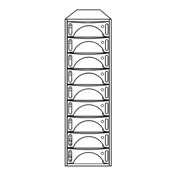
Page 13: Hard Disk Drive Carrier
Figure 1-2. RAIDStation7 Fibre Channel Rackmount Hard Disk Drive Carrier Front loaded hard disk drives are housed in hot-swap carriers. The carriers are of high quality anodized metal construction. This allows for rapid heat dissipation and conforms to the stringent requirements of CE and FCC standards. A diagram of a carrier is shown in Figure 1-3. -
Page 14: Cooling
Introduction Cooling All RAIDStation7 Fibre Channel models feature three Advanced Cooling Mod- ules (ACMs). The modules are mounted at the rear of the unit. In the event of ACM failure, two ACMs are capable of cooling the entire Storage Array until a replacement ACM is installed. - Page 15 Introduction Figure 1-4. AC Power Supply Unit...
- Page 16 Introduction...
-
Page 17: Chapter 2: Unpacking And Initial Setup
Upon receipt, visually inspect the exterior of the packaging for any signs of dam- age. If any damage is found, the shipping company and Adaptec must be notified immediately, and they will advise you of the appropriate action. The cartons are sealed using packaging tape, which should be carefully cut open in the normal manner. -
Page 18: Rackmounting Recommendations
To ensure the safe and efficient operation of the RAIDstation7 Fibre Channel rackmount Storage Array it is essential that you comply with the following guide- lines. Adaptec’s rackmount systems may be installed in closed or open rackmount cabinets by observing the environmental, electrical and mechanical precautions listed in the following sections. -
Page 19: Electrical Considerations
Each shelf should have a grounding braid running from it to this common grounding point (see Figure 2-1 ). A point for securing the grounding braid is provided at the rear of Adaptec rackmount cabi- nets. -
Page 20: Device Insertion
Unpacking and Initial Setup Figure 2-1. Grounding shelves within a 19 in. cabinet Device Insertion This section details how to install power supply units, disk drives, and Advanced Cooling Modules (ACM). The installation of a RAIDStation7 rackmount Storage Array is also covered. The position of the power supplies and the disk drives within the RAIDstation7 Rackmount Storage Array is shown below. -
Page 21: Power Supply Insertion
Power Supply Insertion Power supplies are housed in device carriers for easy insertion. The power supply is designed for hot-swappable operation. NOTE: Leave a delay of at least 1 minute between the removal and installa- tion of the same power supply. Installing a power supply Orient the power supply carrier so that the LEDs are on the top and the ejec- tion button is on the bottom (with the shelf oriented horizontally, as in Fig-... -
Page 22: Advanced Cooling Module Insertion
Unpacking and Initial Setup release the ejection button and turn the key to the right. If the button is not fully protruded, apply additional pressure to the front of the carrier until it is. Pull gently on the carrier to ensue that it does not come out and is locked in place Advanced Cooling Module Insertion The RAIDstation7 Fibre Channel Storage Array supports three ACMs mounted... -
Page 23: Port Bypass Card Insertion
Port Bypass Card Insertion The port bypass cards are located on the rear of the Storage Array (see Figure 3- Installing a port bypass card Hold the port bypass card by it’s handle at 90 Array. Slide the port bypass card into the port bypass card slot. Using the two panel fasteners on the port bypass card secure it in place. - Page 24 Unpacking and Initial Setup...
-
Page 25: Chapter 3: Cabling And Configuration
Storage Array to the host system and how to set the shelf IDs. This chapter does not provide information relating to the connectors on the host system. For this information refer to your Adaptec controller’s users manual. CAUTION: Static electricity can cause damage to both the host system and the RAIDStation7 Fibre Channel Storage Array. -
Page 26: Cabling The Raidstation7 Fibre Channel Storage Array
One port bypass circuit module is always installed as standard (Loop A). There is an upgrade option available from Adaptec to install a second port bypass circuit module (Loop B). With two port bypass circuit modules installed there are two fibre channel loops through which the host system can access data on disk drives while providing full redundancy for the port bypass circuits. -
Page 27: Cabling A Single Raidstation7 Fibre Channel Storage Array With A Single Port Bypass Circuit
Cabling and Configuration system. All data, including data from the Versatile Environmental Monitor (VEM) is carried over this Fibre Channel cable. The following sections will detail how to connect the Fibre Channel cable between the Storage Array and the host system. -
Page 28: Cabling Multiple Raidstation7 Fibre Channel Storage Arrays With A Single Port Bypass Circuit
Cabling and Configuration Connect the HSSDC end of the cable to the Adaptec Fibre Channel controller in the host system. The RAIDstation Fibre Channel Storage Array automatically applies termination to the loop so no external terminators are required. Cabling Multiple RAIDStation7 Fibre Channel Storage Arrays with a Single Port Bypass Circuit This section describes the procedure for daisy-chaining Storage Arrays together. - Page 29 Figure 3-3. Connecting shelves together To host To input connector on next shelf Up to 16 shelves can be connected on the loop, with a maximum of 10 meters between each shelf. Cabling and Configuration Port Bypass Circuit (loop A)
-
Page 30: Dual Port Bypass Circuits
Cabling and Configuration Dual Port Bypass Circuits If two port bypass circuits are used, there must be one Adaptec Fibre Channel controller installed in the host system, with support for two fibre channel loops. The second port bypass circuit is connected to the host system in exactly the same way as the first port bypass circuit. -
Page 31: Setting The Storage Array Ids
Setting the Storage Array IDs Fibre Channel uses a 7 bit binary code for addressing. The 3 Least Significant Bits set the disk drive IDs from ID 0 to ID 6. These 3 bits are set automatically by the backplane. The 4 Most Significant Bits set the fibre disk shelf IDs using hexadecimal num- bering. - Page 32 Cabling and Configuration A Storage Array can have any ID from 0 to F provided no other Storage Array in the loop has the same ID. IDs do not have to be assigned in any order. Table 3-1 lists the decimal number and its corresponding hexadecimal value. Table 3-1 Thumbwheel Switch Value and Corresponding Decimal Value Decimal Hexadecimal...
- Page 33 Table 3-2 Shelf ID and related Bay ID Shelf ID 0 Shelf ID 1 Shelf ID 2 Shelf ID 3 Shelf ID 4 Shelf ID 5 Shelf ID 6 Shelf ID 7 Shelf ID 8 Shelf ID 9 Shelf ID 10 Shelf ID 11 Shelf ID 12 Shelf ID 13...
-
Page 34: Attaching The Raidstation7 Fibre Channel Storage Array To An Ac Power Source
Cabling and Configuration Attaching the RAIDStation7 Fibre Channel Storage Array to an AC Power Source Follow this procedure to connect the RAIDStation7 Fibre Channel Storage Array to a power source: Make sure that the power switch on the rear of the Storage Array is turned off. -
Page 35: Chapter 4 Environmental Monitoring
Chapter 4: Environmental Monitoring This Chapter deals with the methods used to monitor the RAIDstation7 Fibre Channel Storage Array. The methods used are: • Versatile Environmental Monitor (VEM) - The VEM is a card that plugs into the backplane of the RAIDstation7 Fibre Channel Storage Array. The VEM monitors the disk drives, ACM’s, power supplies, and enclosure tempera- ture. -
Page 36: Versatile Environmental Monitor (Vem)
Environmental Monitoring Versatile Environmental Monitor (VEM) The VEM plugs into the backplane of the RAIDstation7 Fibre Channel Storage Array, and is accessible from the rear of the shelf (see Figure 4-1). Figure 4-1. VEM Location Versatile Environmental Monitor (VEM) The VEM communicates with the host system using the SES ports on disk drives 4 and 5 of the Storage Array shelf. -
Page 37: Alarm Silence Button
Figure 4-2. Versatile Environmental Monitor Temperature Condition LED VEM Features • Control of LEDs for each disk drive • Reports drive removals and insertions. • Monitoring for two power supplies • Monitoring/Control for three advanced cooling modules • Reports status and receives control information via the Fibre Channel loop •... -
Page 38: Communications
4 or 5 as shown in Figure 4-3. Figure 4-3.SES communication through disk drives 4 or 5 The host system (via the Adaptec controller, with SES capability) may request information from the VEM through either Fibre Channel disk drive 4 or 5. The host system will send commands through the Fibre Channel cable to either disk drive 4 or 5 (which ever is free to communicate). -
Page 39: Vem Fault Notification
Environmental Monitoring VEM Fault Notification The VEM has an LED mounted on it to warn of over-temperature conditions. If an over-temperature condition exists, the temperature LED (Temp) will come on, and the alarm buzzer will sound. The alarm buzzer can be turned off by using the Mute button on the VEM card. -
Page 40: Disk Drive Carrier Leds
Environmental Monitoring NOTE: Pressing the Mute button on the VEM temporarily silences the alarm buzzer, it does not stop the error LEDs from functioning. Disk Drive Carrier LEDs Each disk drive carrier has two LED indicators on the front as shown in Figure 4- Figure 4-5. -
Page 41: Power Supply Carrier Leds
The Bicolor LED on the the disk drives only flashes Red when a disk drive is present and bypassed, or present and the Fibre Channel loop has failed. The bicolor LEDs on the disk drive carrier will not flash Red if a disk drive is not present. - Page 42 Environmental Monitoring Table 4-2 Power Supply Carrier LED Definitions LED color/location Green: (Top) Red: (Bottom) Meaning activity Power supply is functioning prop- erly. An input power problem exists or the power supply is not functioning properly. Power supply is functioning prop- erly Power supply malfunction or input power problem exists.
-
Page 43: Chapter 5: Removing And Installing Compo- Nents
Removing and Installing Components Chapter 5: Removing and Installing Compo- nents This chapter deals with field replacing components in the RAIDStation7 Fibre Channel Storage Array. Procedures for removing and installing components such as disk drives, power supplies, ACMs, the VEM, and the port bypass circuit mod- ule are covered. -
Page 44: Power Supply Removal And Installation
Removing and Installing Components Power Supply Removal and Installation Power supplies are housed in carriers to allow for easy insertion and removal. The power supply carrier is also designed for hot swappable operation. If removing and replacing the same power supply you must ensure that at least one (1) minute has elapsed between removal and re-insertion. -
Page 45: Disk Drive Carrier Removal And Installation
Removing and Installing Components Disk Drive Carrier Removal and Installation Disk drives are housed in device carriers to allow for easy insertion and removal. Prior to complete removal of the disk drive, you must ensure that the disk drive has fully spun down. This is necessary as centrifugal forces may damage the drive. -
Page 46: Acm Removal And Installation
Removing and Installing Components Advanced Cooling Module (ACM) Removal and Installation The RAIDstation7 Storage Array is supplied with three ACMs mounted on the rear. The ACMs are removable and hot swappable. The air flow created by the ACM is from front to rear. WARNING: Once you have removed an ACM from an operating Storage Array, you must block the resulting hole within 3 minutes. - Page 47 Removing and Installing Components Removing and Installing RAIDStation7 Fibre Channel age Array in a Rackmount Cabinet The rackmount Storage Array can be installed in a standard 19-inch rack cabinet. To ensure correct functionality of the rackmounted Storage Array, the guidelines set out previously regarding environmental recommendations must be followed.
-
Page 48: Vem Removal And Installation
Removing and Installing Components Versatile Environmental Monitor (VEM) Removal and Instal- lation The VEM is located in the rear of the Storage Array. Removing an VEM Switch off power to the Storage Array shelf, ensuring no activity on the fibre loops. -
Page 49: Port Bypass Circuit Removal And Installation
Removing and Installing Components Port Bypass Circuit Removal and Installation The Port Bypass Circuits are located in the rear of the RAIDstation7 Fibre Chan- nel Storage Array. CAUTION: Before removing a Port Bypass Circuit, ensure that all I/O activ- ity to the Storage Array has stopped. Removing a Port Bypass Circuit Loosen the two panel fasteners on the port bypass circuit. - Page 50 Removing and Installing Components...
-
Page 51: Appendix A: Technical Specifications
Appendix A: Technical Specifications GENERAL Host Bus Interface Number of Host Interfaces Maximum Drives per Shelf Devices Supported Drive Interface Redundant and Hot Swappable Power Supply Units (PSU’s) Redundant and Hot Swappable Advanced Cooling Modules (ACM’s) Backplane MONITORING Temperature Monitoring Fan Monitoring Power Supply Monitoring Disk Drive Monitoring... - Page 52 Appendix ELECTRICAL and ENVIRONMENTAL Input Voltage Range (AC) Frequency Range (AC) Operating Temperature Operating Humidity Regulatory Approvals (pending) Warranty PHYSICAL Single Tower 19” Rackmount 85V - 132V or 187V - 264V 47 to 63 Hz C to 40 C, or 41 F to 86 10% to 80%, non-condensing CE, FCC Class A, CSA, UL 1950...
- Page 53 AC Power Supply Advanced Cooling Module Air Flow Cabling Circuit Overloading Communication Configurations Connecting Shelves Together Cooling Device Carrier LEDs 2-5, 5-3 Disk Drive Disk Drive Carrier Enclosure Data Manager Environmental Monitoring 4-5, 4-6, 4-7 Failure LED Fault Notification Fibre Shelf IDs Grounding Maximum Operating Temperature Mechanical Stability...
Need help?
Do you have a question about the RAIDStation RS/7F and is the answer not in the manual?
Questions and answers