
Related Manuals for Kohler Decision-Maker 3000


Summary of Contents for Kohler Decision-Maker 3000
- Page 1 Operation Industrial Generator Sets Models: 10-1000 kW Controller: Decision-Makerr 3000 Software (Code) Version 1.2 or higher TP-6694 7/11c...
-
Page 2: Product Identification Information
California Proposition 65 WARNING Engine exhaust from this product contains chemicals known to the State of California to cause cancer, birth defects, or other reproductive harm. Product Identification Information Product identification numbers determine service parts. Controller Identification Record the product identification numbers in the spaces Record the controller description from the generator set below immediately after unpacking the products so that operation manual, spec sheet, or sales invoice. -
Page 3: Table Of Contents
Table of Contents Product Identification Information Safety Precautions and Instructions ............Introduction . - Page 4 Table of Contents, continued Section 3 Scheduled Maintenance ............Alternator Service .
-
Page 5: Safety Precautions And Instructions
Safety Precautions and Instructions IMPORTANT SAFETY INSTRUCTIONS. Accidental Starting WARNING Electromechanical equipment, including generator sets, transfer WARNING switches, switchgear, and accessories, can cause bodily harm and pose life-threatening danger when improperly installed, operated, or Explosion. maintained. To prevent accidents be aware of potential dangers and act Can cause severe injury or death. - Page 6 Battery gases. Explosion can cause Servicing the fuel system. A flash Carbon monoxide symptoms. severe injury or death. Battery gases fire can cause severe injury or death. Carbon monoxide can cause severe can cause an explosion. Do not smoke Do not smoke or permit flames or nausea, fainting, or death.
- Page 7 Explosive fuel vapors can cause Hazardous Noise WARNING severe injury or death. Take additional precautions when using the CAUTION following fuels: Propane (LP)—Adequate ventilation is mandatory. Because propane is heavier than air, install propane gas Hazardous voltage. detectors low in a room. Inspect the Backfeed to the utility system can detectors manufacturer’s...
- Page 8 Connecting the battery and the WARNING WARNING battery charger. Hazardous voltage can cause severe injury or death. Reconnect battery correctly, positive to positive and negative to negative, to avoid electrical shock and damage to the battery charger and Hot engine and exhaust system. battery(ies).
-
Page 9: Introduction
TT-1405 Setup for Network Communication Information in this publication represents data available at the time of print. Kohler Co. reserves the right to Figure 1 Related Literature change this publication and the products represented without notice and without any obligation or liability Several engine manufacturers provide engines with whatsoever. -
Page 10: Service Assistance
Visit the Kohler Power Systems website at Phone: (86) 21 6288 0500 KohlerPower.com. Fax: (86) 21 6288 0550 Look at the labels and stickers on your Kohler product India, Bangladesh, Sri Lanka or review the appropriate literature or documents India Regional Office included with the product. -
Page 11: Section 1 Specifications And Features
Section 1 Specifications and Features 1.1 Introduction The controller features, accessories, and menu displays depend upon the engine electronic control module The spec sheets for each generator set provide model- (ECM) setup and features. Controller features apply to specific generator and engine information. generator set models with ECM and non-ECM engines controller spec sheet provides specifications for this unless otherwise noted. -
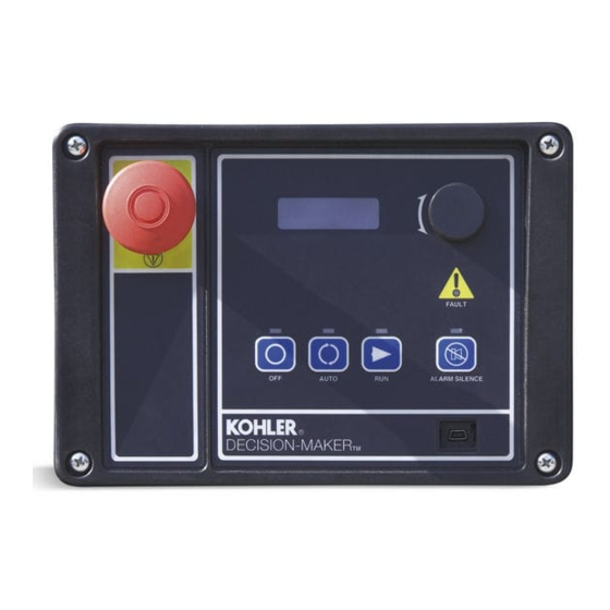
Page 12: Switches And Controls
1.2.1 Switches and Controls Press the dial at a given main menu to access the submenus within the selected main menu. Note: US/Metric Display is selectable in Section When in the submenu, rotate the dial to navigate 1.2.3—Digital Display—Generator Set System through the submenu—clockwise to go forward Menu. - Page 13 System Warning Fault Lamp. Yellow lamp identifies System Shutdown Fault Lamp. Red lamp indicates an existing fault condition that does not shut down the that the generator set has shut down because of a fault generator set. A continuing system warning fault condition.
-
Page 14: Digital Display
1.2.3 Digital Display See 1.2.2—Annunciator Lamps—System Warning Fault Lamp for a list of possible warning faults. Press the pushbutton/rotary selector dial to turn on the controller lamps and display. The lamps and display Generator Set State displays the generator set status: turn off 60 minutes after the last entry. - Page 15 Fuel Level % displays the fuel tank level for diesel- The user can change individual values or can select powered models. This value also shows in the Overview Reset Calib?- -Yes to reset all values. The Reset Calib? Menu. display will only show if calibration is enabled. Refer to the requirements shown with Generator Set Calibration Battery displays the DC voltage of the engine starting in 2.3.7 Status and Notice Digital Displays.
- Page 16 Battery Voltage displays the engine electrical system The user can change individual values or can enter Yes 12 or 24 volts. when Reset all Calib? is displayed. At the end of the Generator Set Calibration menu, Exit calibration is Measurement System displays the user selected unit shown.
- Page 17 Digital Inputs Menu There is an optional 2 input/5 output (I/O) module board available that can provide two additional analog (or This menu allows the user to review the settings. There digital) inputs. are up to three digital inputs that are programmer selectable if not reserved by factory options.
-
Page 18: Controller Fault Diagnostics
1.2.4 Controller Fault Diagnostics that is NOT part of the event history. System events are available as a Relay Output as shown. This table provides descriptions of the system events and their types—warning, shutdown, status, and notice. Throughout this manual there are examples of the display text. - Page 19 Warning Shutdown Status/ Relay Function Function Notice Output Description Display Message Chicago code active * Auto Locked Notice Common fault (includes ]) Common Fault Shutdwn Common warning fault Common Warng Default parameters loaded Default Pars Warning Emergency stop Emerg Stop Shutdwn Engine cooldown (delay) active Eng Cooldown Notice Engine start delay active...
-
Page 20: Digital Display Circuit Board And Connections
1.2.5 Digital Display Circuit Board and 1.2.6 Main Logic Circuit Board Connections The main logic circuit board provides the terminal strips and connection sockets to connect the controller to the The digital display circuit board provides: engine/generator, input/output connections, optional The backlit LCD (liquid crystal display) for monitoring I/O module kit, and circuit protection fuses. -
Page 21: Terminal Jumper
1.2.8 Communication Ports The main logic circuit board contains a single mini USB communication port for PC connections, see Figure 1-6. For Modbusr communication using RS-485, see Figure 1-5 (P21). Refer to the List of Related Materials in the Introduction for corresponding SiteTecht software and/or communication installation information. -
Page 22: Controller Logic Specifications
1.3 Controller Logic Specifications The controller logic specifications section is an overview of the various features and functions of the controller. Certain features function only when optional accessories are connected. See Section 2, Operation, for details. The default selection time delays and digital outputs are factory set and adjustable. - Page 23 Factory-Defined Settings List GenSet Fault Write Time Default Mode Lamp Access Delay Time Always Controller Display Alarm Range Default Range Delay Warning Display Running Message Horn Setting Selection (sec.) (sec.) Description Shutdown SiteTech Stopped Engine Functions Critically high fuel level Fuel Level Critically 0--100% 0--10...
- Page 24 GenSet Fault Write Time Default Mode Lamp Access Delay Time Always Controller Display Alarm Range Default Range Delay Warning Display Running Message Horn Setting Selection (sec.) (sec.) Description Shutdown SiteTech Stopped General Functions Alarm silence, 0--Auto only AlarmSilenceMode 0--1 (NFPA 110), 1--Always Aux.
- Page 25 GenSet Fault Write Time Default Mode Lamp Access Delay Time Always Controller Display Alarm Range Default Range Delay Warning Display Running Message Horn Setting Selection (sec.) (sec.) Description Shutdown SiteTech Stopped Overvoltage (each phase) Volts (L1--L2, L2--L3, or L3--L1) High 105--135% 120% 2--10...
-
Page 26: Voltage Regulator And Calibration Specifications
1.3.2 Voltage Regulator and Calibration Underfrequency Unload Frequency Setpoint. This adjustment affects the voltage droop (volts per Hz) when Specifications load is applied and underfrequency occurs. underfrequency unload setting defines the setpoint The controller has a voltage regulation function that is internal to the processor. -
Page 27: Section 2 Operation
Section 2 Operation 2.1 Prestart Checklist Fuel Level. Check the fuel level and keep the tank(s) full to ensure adequate fuel supply. To ensure continued satisfactory operation, perform the Oil Level. Maintain the oil level at or near, not over, the following checks or inspections before or at each full mark on the dipstick. -
Page 28: Starting
Generator Set Button Alarm Alarm Silence Alarm Status Button Mode Lamp Fault Lamp Horn Button Horn Lamp Controller Display — — — Scrolling Overview Menu Only On (or Cranking) — — — AUTO Green — — Running and then Shutdown Message Pressed Yellow —... -
Page 29: Stopping (User Stopping And Fault Shutdown)
2.3.2 Stopping (User Stopping and switch. Refer to Section 2.3.8, Controller Resetting procedure, to restart the generator set following a fault Fault Shutdown) shutdown. Normal Stopping 1. Investigate and correct the cause of the emergency stop. Run the generator set without load for 5 minutes to ensure adequate engine cooldown. -
Page 30: System Fault Warning Lamp With Digital Displays
2.3.5 System Fault Warning Lamp with Critical High Fuel Level (diesel-powered models only). The fault lamp illuminates yellow and the alarm Digital Displays horn sounds when the fuel tank level on diesel models approaches full. This fault requires an optional critical The system FAULT lamp glows yellow and the alarm horn sounds indicating a warning fault but does not shut high fuel switch and fuel tank for the lamp to function. - Page 31 High Fuel Level (diesel-powered models only). The Low Engine Oil Level. The fault lamp illuminates fault lamp illuminates yellow and the alarm horn sounds yellow and the alarm horn sounds because of low when the fuel tank level on diesel models approaches engine oil level.
-
Page 32: System Fault Shutdown Lamp With Digital Displays
2.3.6 System Fault Shutdown Lamp ECM Address Conflict. The fault lamp illuminates red, the alarm horn sounds, and the unit shuts down when With Digital Displays the controller detects an error with the ECM address. The local display shows ECMAddr Err Shutdwn. The system FAULT lamp glows red, the alarm horn sounds, and the unit shuts down to indicate a fault ECM Communications Loss. - Page 33 High Coolant Temperature. The fault lamp illuminates Low Oil Pressure. The fault lamp illuminates red, the red, the alarm horn sounds, and the unit shuts down alarm horn sounds, and the unit shuts down because of because of high engine coolant temperature. The high low oil pressure.
-
Page 34: Status And Notice Digital Displays
Overvoltage (Each Phase). The fault lamp illuminates 2.3.7 Status and Notice Digital Displays red, the alarm horn sounds, and the unit shuts down Warnings and shutdown faults appear on the digital when the voltage exceeds the overvoltage setting for display and become part of the event history. Beyond the preset time delay period. - Page 35 Engine Start Aid Active. This notice message When calibrating current, the metered value must be at indicates that the start aid is active and will energize an least 25% of the rated current on units smaller than engine equipped preheat or ether system during the 100 kW and at least 50 amps on units rated larger than crank cycle.
-
Page 36: Controller Resetting (Following System Shutdown Or Warning)
Voltage Regulator Adjustment (User Defined). This 4. Test operate the generator set to verify correction feature is in the Voltage Regulator Menu allowing the of the shutdown cause. user to fine adjust the output voltage. Use the 5. Press generator master control Pushbutton/Rotary Selector Dial to navigate and select... - Page 37 (Legend: D First level submenu, d second level submenu) Menu Summary List Overview Generator Metering GenSet System Voltage Regulator Menu Menu Menu Menu (Version 3.0.25 or Higher) D System Frequency D Total Power kVA (shown Available as scrolling or D Voltage Regulator Voltage D System Phase (Single fixed display text as actual output values)
-
Page 38: Monitoring And Programming Setup
2.5 Monitoring and Programming Setup Modbusr/ Ethernet Ethernet Network Converter The user programmer can access the controller data Generator Set Personal Controller or with the controller digital display or a personal computer Computer Transfer with NIC (PC) with optional SiteTecht software to monitor and/or Switch Control Remote RS-232 to... -
Page 39: Reviewing Menu Displays
2.6 Reviewing Menu Displays Controller Controller SiteTech Menu Name Viewable Adjustable Adjustable Use this section to review a summary of the generator Overview set controller data. See Figure 2-11 or Figure 2-12 for Engine Metering which menus provide data monitoring, data adjustments, or require SiteTecht software to make Generator Metering... -
Page 40: Overview
2.6.2 Overview Overview (Fixed Display) Overview ----> ### V ##.# Hz Displays basic and commonly sought after information ##.# hr ### A #### kW about the generator set. This information scrolls automatically after about 5 minutes of no user input English Display ###_F ###%... -
Page 41: Generator Metering (And Calibration)
2.6.4 Generator Metering (and Momentarily press the pushbutton/rotary selector dial. Stop the generator set if not already done. Calibration) Displays generator output data including line-to-line and Generator Metering line-to-neutral voltages, current, frequency, total kilowatts, and total kVA. The menu displays Generating---->... -
Page 42: Genset Information
2.6.5 GenSet Information Display for Measurement System is user selectable as English or Metric. Displays generator set and controller information. Displayed data is factory entered. Contrast display is user adjustable to help improve digital display visibility in dimly lit rooms or in direct sunlight. -
Page 43: Genset Calibration
2.6.8 GenSet Calibration The user can individually calibrate the values or reset all of them. The local display Reset all calib? No or Yes. This menu is only available in controller firmware Select No to make no changes and exit GenSet versions before 3.0.25. -
Page 44: Voltage Regulator
2.6.9 Voltage Regulator running, enter Yes when the Enter volt reg? is displayed. The user can review the value but attempting to change Before Firmware Version 3.0.25. the value will cause a Cannot edit when stopped error message. Displays the voltage regulator adjustment value. All other voltage regulator adjustments are changed using If the unit is running and Yes is entered when the Enter SiteTecht software. -
Page 45: Digital Inputs
2.6.10 Digital Inputs Inhibit Time Delay. The inhibit time delay is the time period following crank disconnect during which the Displays the selected programming user-defined digital generator set stabilizes and the controller does not notice, warning, and shutdown inputs. These inputs detect the fault or status event. -
Page 46: Digital Outputs
2.6.11 Digital Outputs Digital Outputs Digital ----> DOut A1 Displays the selected programming user-defined digital Outputs ##### notice, warning, and shutdown outputs. These outputs provide a multitude of choices for configuring DOut A1 customized auxiliary outputs. See Figure 2-14 for a list Value: True or False of digital output choices. -
Page 47: Analog Inputs
Critical High No Signal High High Warning Warning Shutdown Shutdown Shutdown Warning Digital Outputs Notice Warning Shutdown AC Sensing Lost Alternator Protection Auxiliary Input Battery Charger Fault Battery Voltage Chicago Code Active Common Fault Common Warning Cranking Voltage ECM Comm Loss Emergency Stop Engine Coolant Level Engine Coolant Temperature... -
Page 48: Event Log
All analog input selection and setup adjustments are 2.6.14 Volt Select done using SiteTecht software. The following terms This menu is only available in controller firmware and descriptions are part of the setup procedure. version 2.8.22 and higher. Enabled. This menu indicates whether or not the This menu allows the user to readily change controller input is enabled. -
Page 49: Section 3 Scheduled Maintenance
Section 3 Scheduled Maintenance Under normal operating conditions, the generator set’s Disabling the generator set. Accidental starting can cause severe injury or death. Before working on the alternator requires no routine service. Consult generator set or connected equipment, disable the generator Section 2.1, Prestart Checklist, for a list of routine set as follows: (1) Move the generator set master switch to the checks. -
Page 50: Service Schedule
3.3 Service Schedule Action System—Component Visually Inspect Check Change Clean Test Interval Fuel System Day tank level Weekly Flexible lines and connections Weekly Fuel level switch Weekly Main tank supply level Weekly Solenoid valve operation Weekly Transfer pump operation Weekly Water in system, remove Weekly Filter(s) - Page 51 Service Schedule, continued Action System—Component Visually Inspect Check Change Clean Test Interval AC Electrical System Controller lamp test Weekly General Inspection Weekly Circuit breakers, fuses[ Monthly Wire abrasions where subject to motion Quarterly Safety and alarm operation Six Months Tighten control and power wiring connections Yearly Transfer switch main contacts[ Yearly...
-
Page 52: Alternator Bearing Service
3.4 Alternator Bearing Service Have an authorized service distributor/dealer perform service. 3.4.1 20- -300 kW Models Replace the end bracket bearing every 10,000 hours of operation in prime power applications. Service the bearing more frequently if the annual inspection indicates excessive rotor end play or bearing damage. The sealed end bracket bearing requires no additional lubrication. -
Page 53: Lpg Liquid Withdrawal Fuel System Concept
3.6.2 LPG Liquid Withdrawal Fuel Natural Gas Operation System Concept Disconnect lead 65 from lead N5. Disconnect lead 73B from the fuel valve. With the LPG liquid withdrawal fuel system, pressurized Connect lead 73A to the fuel valve. liquid LPG fuel passes from the tank to a vaporizer. The vaporizer converts the liquid fuel to gas before sending it LPG Vapor Operation to the fuel mixer. - Page 54 ADV-7600B-B Figure 3-4 Gas Fuel Connections Wiring Diagram Section 3 Scheduled Maintenance TP-6694 7/11...
-
Page 55: Crankcase Ventilation (Ccv) Heater Kit Gm78171-Kp1
Emissions certified models use a single electronic- Allow the engine to cool. Release pressure from the cooling system before removing the pressure cap. To controlled pressure regulator (EPR) for both fuels. A tee fitting connects both fuels together upstream of the release pressure, cover the pressure cap with a thick cloth and then slowly turn the cap counterclockwise to EPR. -
Page 56: Procedure To Drain Cooling System
3.8.3 Procedure to Drain Cooling 3. Open the air-bleed petcocks, if equipped. Close the air-bleed petcocks when coolant begins to flow System from them. For optimum protection, drain, flush, and refill the 4. Add coolant additives or water pump lubricants cooling system at the intervals listed in the service according engine... -
Page 57: Battery
3.9 Battery Refer to this section for general battery information and maintenance. All generator set models use a negative ground with a 12-volt or 24-volt engine electrical system. WARNING Consult the generator set nameplate for the engine electrical system voltage. Consult the generator set spec sheet for battery capacity recommendations for replacement purposes. -
Page 58: Clean Battery
temperatures, run the generator set 20--30 minutes to mix the electrolyte and the water to prevent battery damage from freezing. 1-046 1. Filler caps KW-272000-B 2. Electrolyte level 1. To positive (+) terminal on starter solenoid. 2. To ground (--) terminal on or near starter motor. Figure 3-9 Battery Electrolyte Level Inspection 3. -
Page 59: Charge Battery
3.10 Storage Procedure Correction ° ° 71.1 + .032 Perform the following storage procedure before taking a + .030 generator set out of service for three months or longer. 65.6 + .028 Example No. 1 Follow the engine manufacturer’s recommendations, if + .026 available, for fuel system and internal engine °... -
Page 60: Internal Engine Components (Gas-Fueled Engines)
Gas-Fueled Engines 3.10.5 Exterior 1. Start the generator set. 1. Clean the exterior surface of the generator set. 2. With the generator set running, shut off the gas 2. Seal all engine openings except for the air intake supply. with nonabsorbent adhesive tape. 3. -
Page 61: Section 4 General Troubleshooting
Section 4 General Troubleshooting This section contains generator set troubleshooting, Maintain a record of repairs and adjustments performed diagnostic, and repair information. on the equipment. If the procedures in this manual do not explain how to correct the problem, contact an Use the following charts to diagnose and correct authorized distributor/dealer. -
Page 62: General Troubleshooting Chart
Section 4 Troubleshooting TP-6694 7/11... - Page 63 TP-6694 7/11 Section 4 Troubleshooting...
- Page 64 Section 4 Troubleshooting TP-6694 7/11...
-
Page 65: Controller Display And Voltage Regulation Troubleshooting Chart
TP-6694 7/11 Section 4 Troubleshooting... - Page 66 Notes TP-6694 7/11...
-
Page 67: Section 5 Voltage Reconnection
Section 5 Voltage Reconnection 5.1 Introduction Disabling the generator set. Accidental starting can cause severe injury or death. Before working on the generator set or equipment connected to the set, disable the Use the following voltage reconnection procedure to generator set as follows: (1) Turn the generator set master change the voltage of 10- and 12-lead generator sets. -
Page 68: Voltage Reconnection Procedure (Software Version 2.8 Or Higher)
5.2 Voltage Reconnection 8. Use Figure 5-2, Figure 5-3, or Figure 5-4 to determine the generator set voltage configuration. Procedure Note the original voltage and reconnect as needed. (Software version 2.8 or higher) Route leads through current transformers (CTs) and connect them according to the diagram for the 1. - Page 69 Figure 5-2 20--150 kW Permanent Magnet Single-Phase Alternators, ADV-5875A-M TP-6694 7/11 Section 5 Voltage Reconnection...
- Page 70 Figure 5-3 20--300 kW (190--480 Volt) Permanent Magnet Alternators, ADV-5875B-M Section 5 Voltage Reconnection TP-6694 7/11...
- Page 71 Figure 5-4 20--300 kW (600 Volt) Alternators, ADV-5875C-M TP-6694 7/11 Section 5 Voltage Reconnection...
- Page 72 Figure 5-5 300 kW and Larger Pilot-Excited, Permanent Magnet 4M/5M/7M/10M Alternators, ADV-5875D-M Section 5 Voltage Reconnection TP-6694 7/11...
-
Page 73: Section 6 Accessories
Section 6 Accessories 6.1 Accessories and Connections The optional common fault relay shown in Figure 6-3 as DCB2 has contacts rated at 10 amps at 28 VDC or Several accessories help finalize installation, add 120 VAC and can be connected to user-supplied convenience to operation and service, and establish accessories. -
Page 74: Float/Equalize Battery Charger Kit With Alarm Option
6.1.2 Float/Equalize Battery Charger Kit 6.1.3 Gas Fuel Valve Kit with Alarm Option This section provides the wiring information for an additional gas fuel valve kit required for UL Approval. The float/equalize battery charger with alarm option See Figure 6-6. Refer to the respective generator set provides battery charging to the engine starting wiring diagrams for additional information and for LP battery(ies) and connects to the controller for fault... -
Page 75: Input/Output (I/O) Module Board
6.1.4 Input/Output (I/O) Module Board Figure 6-8 for connections of analog inputs. Refer to Figure 6-27 for accessory connections. The I/O module board provides a generator set mounted panel with two analog or digital inputs and five digital See Section 6.2, Accessory Connections, for terminal outputs. -
Page 76: Low Fuel (Level/Pressure) Switch
6.1.5 Low Fuel (Level/Pressure) Switch 6.1.6 Prime Power Switch Kit Some gas-fueled models offer a low fuel pressure The prime power switch kit prevents battery drain during switch. The low fuel pressure switch connects to the generator set non--operation periods and when the same controller terminal as the low fuel level switch on generator set battery cannot be maintained by an AC diesel-fueled models. -
Page 77: Remote Emergency Stop Kit
6.1.7 Remote Emergency Stop Kit 6.1.8 Remote Reset Feature The emergency stop kit allows immediate shutdown of The remote reset switch provides generator set the generator set from a remote location. controller resetting after a fault shutdown at a remote Figure 6-14 and Figure 6-15. -
Page 78: Remote Serial Annunciator
6.1.9 Remote Serial Annunciator RSA II is an annunciator panel offered in several kit configurations to support Kohler power equipment. The RSA II is a remote serial annunciator Figure 6-18 and Figure 6-19 that monitors the condition of the generator set and/or ATS from a remote location. - Page 79 System Monitoring LEDs and Functions Common System Generator Communication Common Fault Fault Ready LED Running LED Status LED Fault LED Output Horn Fault and Status Condition Overcrank Shutdown Red SF Green Red SF High Engine Temperature Warning * Yellow Red SF Green Green Red SF...
-
Page 80: Run Relay Kit
6.1.10 Run Relay Kit 6.1.11 Shunt-Trip Line Circuit Breaker The run relay kit energizes only when the generator set A shunt-trip line circuit breaker provides a 12- or 24-DC runs. Use the run relay kit to control air intake and volt solenoid within the line circuit breaker case that can radiator louvers, alarms, and/or other signalling energize the trip mechanism. -
Page 81: Accessory Connections
6.2 Accessory Connections The controller contains a circuit board equipped with terminal strip(s) for use in connecting external optional accessories including alarms, battery chargers, and remote switches. The optional I/O board provides an additional two analog or digital inputs and five digital outputs. - Page 82 TB1 Terminal Strip P1 24-Pin Connector Analog and Digital Input Connections Engine Wiring Harness Terminal Description Connection Terminal Description Connection TB1--DI 1 DCH1 No Function P1--12 14P +12VDC Prime Power Switch TB1--DI 2 DCH2 Aux. Warning Switch P21 6-Pin Connector TB1--DI 3 DCH3 Battery Charger Fault...
- Page 83 P25 Connector P30 Connector RJ45 Remote I/O In 2 Amp. K2 Relay Output (2.2) Connections Connects to DEC 3000 P23 Terminal Description P26 Connector P30--NC Normally Closed RJ45 Remote I/O Out P30--COM Common Open P30--NO Normally Open P27 Connector P31 Connector CAN Terminator 2 Amp.
- Page 84 Figure 6-28 Decision-Makerr 3000 Wiring Connections GM67191-B Section 6 Accessories TP-6694 7/11...
-
Page 85: Appendix A Abbreviations
(2 bytes) est. estimated Canadian Electrical Code KBus Kohler communication protocol E-Stop emergency stop cert. certificate, certification, certified kilogram etc. et cetera (and so forth) cubic feet per hour TP-6694 7/11 Appendix 85... - Page 86 kg/cm kilograms per square National Bureau of Standards remote terminal unit centimeter normally closed room temperature vulcanization kilogram-meter National Electrical Code read/write kg/m kilograms per cubic meter NEMA National Electrical Society of Automotive kilohertz Manufacturers Association Engineers kilojoule NFPA National Fire Protection scfm standard cubic feet per minute Association...
-
Page 87: Appendix B Programmer-Defined Settings
Appendix B Programmer-Defined Settings Use the table below to record programmer-defined SiteTecht setup software is required for programming the Decision-Makerr 3000 controller. Contact your local settings during the generator set controller setup and distributor/dealer for assistance. calibration. The controller default settings and ranges provide guidelines. - Page 88 GenSet Write Mode Time Default Access Delay Time Programmer- Always Controller Display Range Default Defined Range Delay Display Running Message Setting Selection Settings Description (sec.) (sec.) SiteTech Stopped Low fuel pressure Fuel Press Low Not adjustable (gas models) * Warning Low oil pressure Fixed (Fixed...
- Page 89 GenSet Write Mode Time Default Access Delay Time Programmer- Always Controller Display Range Default Defined Range Delay Display Running Message Setting Selection Settings Description (sec.) (sec.) SiteTech Stopped System ready System Ready Status Not adjustable System timer failed Timer Error Notice Not adjustable Generator Functions AC sensing loss...
- Page 90 Notes 90 Appendix TP-6694 7/11...
-
Page 91: Appendix C Voltage Regulator Definitions And Adjustments
Appendix C Voltage Regulator Definitions and Adjustments following definitions adjustment/setting mathematically by Ohm’s law, which states that power is specifications are intended for users planning to adjust equal to the voltage squared divided by the impedance. the voltage regulator beyond the default settings in As the voltage is reduced, the power delivered by the order to customize the alternator for a specific alternator decreases by a squared relationship. - Page 92 Frequency Setpoint or Cut-In Point general, the phase with the greatest load will have the lowest voltage while the phase with the least load will The point at which the underfrequency unloading begins have the highest voltage. This is true regardless of the to take effect is adjustable, allowing the system to be type of sensing used in the regulator system.
- Page 93 As a reference, the present voltage adjust setting is Frequency Setpoint displayed as well as the average value of the line-to-line The frequency setpoint is the cut-in point for voltages. The individual line-to-line voltages are also underfrequency unloading. At any operating frequency displayed on the subsequent menu screens.
- Page 94 Notes 94 Appendix TP-6694 7/11...
-
Page 95: Appendix D Alternator Protection
Appendix D Alternator Protection The controller has built-in thermal protection for the The current and time limits are defined by actual test alternator. This feature functions similarly to a thermal data and are maintained in the personality parameter circuit breaker. When the output current exceeds the file. - Page 96 Notes 96 Appendix TP-6694 7/11...
- Page 97 Notes TP-6694 7/11...
- Page 98 Notes TP-6694 7/11...
- Page 100 For the nearest sales/service outlet in the US and Canada, phone 1-800-544-2444 KohlerPower.com Kohler Power Systems Asia Pacific Headquarters TP-6694 7/11c 7 Jurong Pier Road Singapore 619159 E 2010, 2011 by Kohler Co. All rights reserved. Phone (65) 6264-6422, Fax (65) 6264-6455...
Need help?
Do you have a question about the Decision-Maker 3000 and is the answer not in the manual?
Questions and answers