Table of Contents
Advertisement
Manual
F Series Motor Controller
For Controllers: AC F4-A Model, AC F6-A Model
» Software Device Profile: 4.5.0.0 «
Read Instructions Carefully!
Specifications are subject to change without notice.
© 2022 Curtis Instruments, Inc. ® Curtis is a registered trademark of Curtis Instruments, Inc.
© The design and appearance of the products depicted herein are the copyright of Curtis Instruments, Inc.
AC F2-A Model
Curtis Instruments, Inc.
200 Kisco Avenue
Mt. Kisco, NY 10549
www.curtisinstruments.com
53240, Rev A April 2022
Advertisement
Table of Contents
Troubleshooting

Subscribe to Our Youtube Channel
Related Manuals for Kohler Curtis F Series


Summary of Contents for Kohler Curtis F Series
- Page 1 Manual F Series Motor Controller For Controllers: AC F4-A Model, AC F6-A Model AC F2-A Model » Software Device Profile: 4.5.0.0 « Curtis Instruments, Inc. 200 Kisco Avenue Mt. Kisco, NY 10549 www.curtisinstruments.com Read Instructions Carefully! Specifications are subject to change without notice. ©...
-
Page 2: Table Of Contents
TABLE OF CONTENTS CHAPTERS 1: OVERVIEW ............................1 HOW TO USE THIS MANUAL ......................3 WHAT IS NEW IN FOS 4.4.0.0 ... HIGHLIGHTS ................4 GETTING THE MOST OUT OF YOUR CURTIS CONTROLLER ............. 4 2: INSTALLATION AND WIRING ......................5 PHYSICALLY MOUNTING THE CONTROLLER ................... - Page 3 TABLE OF CONTENTS cont’d 3: APPLICATION-SPECIFIC FEATURES ....................32 MOTOR SPEED CONSTRAINTS ..................... 32 VOLTAGE LIMITS .......................... 33 OVER-VOLTAGE REGION ......................34 SEVERE OVER-VOLTAGE REGION .................... 34 UNDER-VOLTAGE REGION ...................... 34 OUTPUT-DISABLED REGION ....................35 BROWNOUT VOLTAGE ......................35 KSI AND B+ INPUT......................... 35 BATTERY DISCHARGE INDICATOR ....................
- Page 4 TABLE OF CONTENTS cont’d 5: SYSTEM MONITOR MENU ......................145 6: COMMISSIONING .......................... 156 INITIAL SETUP ..........................156 TO BEGIN ..........................157 CONTROL MODE SELECTION ....................158 PARAMETER SETTINGS – METHOD OVERVIEW ..............158 TRACTION MOTOR SETUP GUIDE ..................159 CONTROLLER SETUP GUIDE ....................
- Page 5 TABLE OF CONTENTS cont’d 8: MAINTENANCE ..........................239 CLEANING........................... 239 FAULT HISTORY ........................... 239 APPENDIX A ............................240 CANOPEN PDO MAPPING OBJECT DESCRIPTION ..............240 EXAMPLE FOR RPDO MAPPING WITH THE CIT PROGRAMMER ..........242 EXAMPLE FOR TPDO MAPPING WITH THE PROGRAMMER ............. 244 EXAMPLE FOR RPDO MAPPING WITH SDO WRITES ..............
- Page 6 TABLE OF CONTENTS cont’d TABLES TABLE 1: HIGH POWER CONNECTIONS ....................8 TABLE 2: THE AMPSEAL CONNECTOR COMPONENTS & PART NUMBERS ..........10 TABLE 3: THE AMPSEAL CONNECTOR COMPONENTS & PART NUMBERS ..........10 TABLE 4: THE AMPSEAL CONNECTION PROTECTED VOLTAGES – 23 PIN CONTROLLERS ..... 13 TABLE 5: AMPSEAL CONNECTIONS PROTECTED VOLTAGES –...
- Page 7 TABLE OF CONTENTS cont’d FIGURES FIGURE 1: AC F2-A MOTOR CONTROLLER ................... 1 FIGURE 2: AC F4-A MOTOR CONTROLLER ................... 2 FIGURE 3: AC F6-A MOTOR CONTROLLER ................... 3 FIGURE 4: AC F2-A DIMENSIONS ......................5 FIGURE 5: AC F4-A DIMENSIONS ......................6 FIGURE 6: AC F6-A DIMENSIONS ......................
- Page 8 TABLE OF CONTENTS cont’d FIGURE 26: INTERLOCK BRAKE SUPERVISION SPEED LIMIT FOR NEGATIVE INITIAL SPEED ....87 FIGURE 27: INTERLOCK BRAKE SUPERVISION DISTANCE CHECK ............87 FIGURE 28: HYDRAULIC SYSTEM DIAGRAM, WITH LOAD-HOLD AND PROPORTIONAL LOWER VALVES ................89 FIGURE 29: HYDRAULIC SYSTEM DIAGRAM, WITH A FIXED (ON/OFF) LOAD-HOLD VALVE ..... 90 FIGURE 30: LIFT-INPUT SIGNAL CHAIN (PROCESSING) ...............
-
Page 9: 1: Overview
Curtis AC F2-A, F4-A, F6-A Motor Controllers – FOS 4.5 – April 2022 Return to TOC 1 — OVERVIEW The Curtis F2-A and F4/6-A motor controllers provide accurate, dependable, and highly efficient control of speed and torque of AC induction motors (ACIM) and permanent magnet AC motors (PMAC). These traction controllers are optimized for both class III pedestrian-operated (F2-A) and rider- powered (F4/6-A) pallet trucks. -
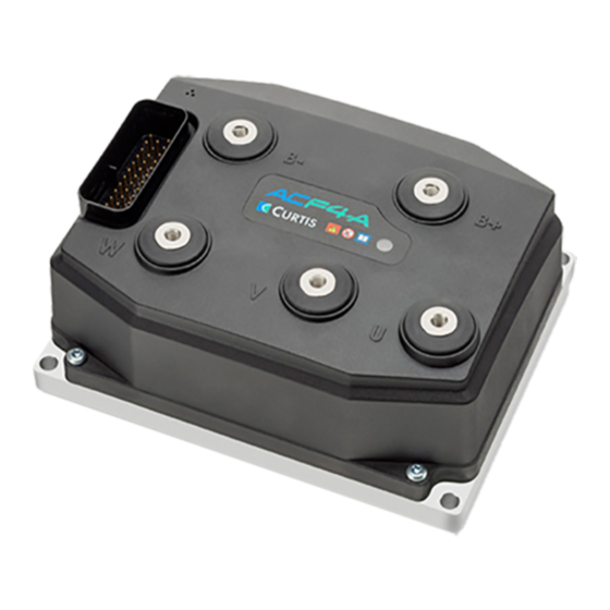
Page 10: Figure 2 Ac F4-A Motor Controller
Curtis AC F2-A, F4-A, F6-A Motor Controllers – FOS 4.5 – April 2022 Return to TOC Figure 2 AC F4-A Motor Controller pg. 2 1 — OVERVIEW... -
Page 11: How To Use This Manual
Curtis AC F2-A, F4-A, F6-A Motor Controllers – FOS 4.5 – April 2022 Return to TOC Figure 3 AC F6-A Motor Controller HOW TO USE THIS MANUAL This manual combines the 23-pin F2-A and the 35-pin F4/6-A controllers. The F-Series I/O operates the same way, the difference lies in the input/output (I/O) count. The 35-pin controllers offer a second CAN port and more I/O (drivers, analog &... -
Page 12: What Is New In Fos 4.4.0.0
Curtis AC F2-A, F4-A, F6-A Motor Controllers – FOS 4.5 – April 2022 Return to TOC WHAT IS NEW IN FOS 4.5.0.0 ... HIGHLIGHTS 1. Expanded the motor temperature sensor type to include the mapping of a custom sensor. See the parameter Sensor Type (0x3688) = 0. -
Page 13: 2: Installation And Wiring
Curtis AC F2-A, F4-A, F6-A Motor Controllers – FOS 4.5 – April 2022 Return to TOC 2 — INSTALLATION AND WIRING PHYSICALLY MOUNTING THE CONTROLLER Use the controller's outline and mounting-hole dimensions to determine the optimum mounting location. Properly installed, the controller meets the IP65 requirements for environmental protection against dust and water. -
Page 14: Figure 5 Ac F4-A Dimensions
Curtis AC F2-A, F4-A, F6-A Motor Controllers – FOS 4.5 – April 2022 Return to TOC Figure 5 STATUS LED 5X M6X 1.0 - 6H 18 MIN AC F4-A dimensions 129.0 140.0 4X ø 7.0 169.0 180.0 74.0 75.0 12.0 Dimensions are in millimeters Working on electrical systems is potentially dangerous. -
Page 15: Precautions
Curtis AC F2-A, F4-A, F6-A Motor Controllers – FOS 4.5 – April 2022 Return to TOC 200.6 STATUS LED 140.4 7.00±0.13 5X M6X1.0 20.0 Part Number: XXXXXXXX 73.9 MODEL: XXXXXXXXX VOLTAGE: XXXXXXX CURRENT: XXXX Serial Number: XXXXXXXXXXX 11.0 Figure 6 AC F6-A dimensions PRECAUTIONS Take the steps during the application’s design and development to ensure that the EMC performance... -
Page 16: High Current Connections
Curtis AC F2-A, F4-A, F6-A Motor Controllers – FOS 4.5 – April 2022 Return to TOC HIGH CURRENT CONNECTIONS There are five high-current connections identified on the controller cover as B+, B–, U, V, and W. Install the controller with a (main) contactor between the traction battery positive terminal and the B+ terminal. -
Page 17: Low Current Connections
Curtis AC F2-A, F4-A, F6-A Motor Controllers – FOS 4.5 – April 2022 Return to TOC LOW CURRENT CONNECTIONS All logic and low power connections are through a single 23 or 35-pin AMPSEAL connector (mold in the cover) utilizing gold-plated pins. The matching AMPSEAL receptacle’s wire silos come sealed by a membrane. -
Page 18: Table 2 The Ampseal Connector Components & Part Numbers
Curtis AC F2-A, F4-A, F6-A Motor Controllers – FOS 4.5 – April 2022 Return to TOC Table 2 The AMPSEAL Connector Components & Part Numbers Matching AMPSEAL 23-pin Component* Part Number AMPSEAL receptacle housing (the black vehicle-harness plug) 770680-1 Plug’s gold-plated socket terminals (strip form p/n) 770520-3 Plug’s gold-plated socket terminals (loose piece p/n) 770854-3... -
Page 19: Figure 10 23-Pin Ampseal Connection Assignments
Curtis AC F2-A, F4-A, F6-A Motor Controllers – FOS 4.5 – April 2022 Return to TOC Figure 10 23-Pin AMPSEAL Connection Assignments SWITCH SWITCH SWITCH 14/+12V SWITCH MOTOR SWITCH SWITCH WIPER TEMP SWITCH DRIVER DRIVER COIL RETURN DRIVER DRIVER DRIVER Figure 11 35-Pin AMPSEAL ISOLATED GROUND... -
Page 20: Rotor Position Feedback
Curtis AC F2-A, F4-A, F6-A Motor Controllers – FOS 4.5 – April 2022 Return to TOC Rotor Position feedback The rotor-position sensor’s wiring (+5V, Feedback A, Feedback B, and Ground) should be bundled together between the motor and controller. These wires are often run with the rest of the low current wiring harness without interference issues, but the encoder wires should not be routed near the motor cables. -
Page 21: Table 4 The Ampseal Connection Protected Voltages - 23 Pin Controllers
Curtis AC F2-A, F4-A, F6-A Motor Controllers – FOS 4.5 – April 2022 Return to TOC Table 4 The AMPseal Connection Protected Voltages – 23 pin controllers Controller Minimum Maximum Pin Number Reverse Voltage Voltage Air Discharge Contact (non-contact) (touch) Inputs 3, 4, 5, 6, 7, 8, 9, 10, 11, 14, 15, 17, 18, 19, Indefinite short to B+ and B–... -
Page 22: Controller Inputs And Outputs
Curtis AC F2-A, F4-A, F6-A Motor Controllers – FOS 4.5 – April 2022 Return to TOC Controller Inputs and Outputs Tables 6 and 7 list the available Inputs and Outputs (I/O) types by the AMPSEAL pin number. Table 6 Logic and Low Current Connections-F2A Wiring Diagram Analog Switch... -
Page 23: Table 7 Logic And Low-Current Connections-F4/6-A
Curtis AC F2-A, F4-A, F6-A Motor Controllers – FOS 4.5 – April 2022 Return to TOC Table 7 Logic and Low-Current Connections-F4/6-A Special I/O Digital Input Switch Analog Pin Name Number (Alternative usage) (type) Input Input Driver Input 20 Virtual Driver 1 Input 21 Driver... -
Page 24: Controller Wiring Diagram (Examples)
Curtis AC F2-A, F4-A, F6-A Motor Controllers – FOS 4.5 – April 2022 Return to TOC Controller Wiring Diagram (Examples) The basic wiring diagrams for a Class III pallet truck use wired inputs from switches and potentiometers, driving the traction motor. The Interlock, Forward, Reverse, Lift, Lower, and the redundant Emergency Reverse inputs are by external mechanical switches pulled to KSI (B+). -
Page 25: Figure 13: Ac F4-A, F6-A Basic Wiring Diagram
Curtis AC F2-A, F4-A, F6-A Motor Controllers – FOS 4.5 – April 2022 Return to TOC AC F4-A/F6-A CONTROLLER Interlock Input 5 Emergency Input 9 Coil Supply Reverse Proportional Valve Driver 1 / Input 21 Input 13 / Enc 2B EM Brake Forward Input 7... -
Page 26: Figure 14: Ac F2-A Can Tiller Head Wiring Diagram
Curtis AC F2-A, F4-A, F6-A Motor Controllers – FOS 4.5 – April 2022 Return to TOC For CANopen based tiller heads (or similar), see the Figures 14 and 15 wiring examples. In these CAN-based examples, the Interlock, Emergency Reverse, and a Travel Limit are the remaining “wired”... -
Page 27: Figure 15: Ac F4-A, F6-A Isolated Can. Tiller Head Wiring Diagram
Curtis AC F2-A, F4-A, F6-A Motor Controllers – FOS 4.5 – April 2022 Return to TOC AC F4-A/F6-A CONTROLLER Interlock Input 5 Emergency Input 9 Coil Supply Reverse Proportional Valve Input 13 / Enc 2B Driver 1 / Input 21 Travel EM Brake Safety Disabled... -
Page 28: Low Current Connector Electrical Specifications
Curtis AC F2-A, F4-A, F6-A Motor Controllers – FOS 4.5 – April 2022 Return to TOC Low Current Connector Electrical Specifications Digital (Switch) Inputs The controllers offer flexibility in configuring the digital inputs. For example, when configured as switch inputs, the available inputs easily interface with user switches/buttons for the following: •... - Page 29 Curtis AC F2-A, F4-A, F6-A Motor Controllers – FOS 4.5 – April 2022 Return to TOC Table 8 Digital (Switch) Inputs Electrical Specifications, cont’d Signal Name 23-Pin 35-Pin Logic Threshold Input Impedance AVAILABLE/ALTERNATIVE SWITCH (DIGITAL) INPUTS (Throttle Wiper, typical usage) >...
-
Page 30: Analog Inputs
Curtis AC F2-A, F4-A, F6-A Motor Controllers – FOS 4.5 – April 2022 Return to TOC Analog Inputs The controllers support a variety of analog inputs. The input’s allowable voltage range varies depending on the primary purpose of the input. Select the analog input that matches the application. Table 9 Analog Inputs Electrical Specifications Input/Signal Name 23-Pin... -
Page 31: Potentiometer Inputs With Dynamic Testing
Curtis AC F2-A, F4-A, F6-A Motor Controllers – FOS 4.5 – April 2022 Return to TOC Potentiometer Inputs with Dynamic Testing In this manual, the term throttle is for the traction motors. If the vehicle uses a dual drive system, the single throttle input controls both traction motors. -
Page 32: Pwm And Digital Drivers
Curtis AC F2-A, F4-A, F6-A Motor Controllers – FOS 4.5 – April 2022 Return to TOC Table 10 Potentiometer Input/Configuration Electrical Specifications Input Pot Resistance Range Input Output Fault 23-Pin 35-Pin Type Signal Name Available Current Impedance Voltage Detection Pot 6 Supply Pot Wiper Open Pot 1 Wiper 3-Wire... -
Page 33: Table 11 Driver Outputs Electrical Specifications
Curtis AC F2-A, F4-A, F6-A Motor Controllers – FOS 4.5 – April 2022 Return to TOC Drivers 6 and 7 are lower-current digital (On/Off) drivers. Use the drivers for dashboard LEDs, piezo-electric buzzers and other low-current switched loads (i.e., high input impedance devices able to accept full coil supply voltage). -
Page 34: Power Supply Outputs
Curtis AC F2-A, F4-A, F6-A Motor Controllers – FOS 4.5 – April 2022 Return to TOC Power Supply Outputs The 5-volt and 12-volt power supplies provide auxiliary power for low power circuits such as electronic throttles, displays/gauges, and motor-position feedback devices. The corresponding ground is the controller I/O ground circuit, GND. -
Page 35: Keyswitch And Coil Supply
Curtis AC F2-A, F4-A, F6-A Motor Controllers – FOS 4.5 – April 2022 Return to TOC Keyswitch and Coil Supply Connect the Keyswitch (KSI) input to B+ via a keyswitch. The keyswitch input feeds the controller’s internal power supplies, the Coil Supply output, and the main-capacitor bank’s precharge (before the main contactor closes). -
Page 36: Motor Position Sensor Inputs
Curtis AC F2-A, F4-A, F6-A Motor Controllers – FOS 4.5 – April 2022 Return to TOC The supported protocol is CANopen Physical layer ISO 11898, including the 11-bit and 29-bit identifier protocols. For applications with multiple third party devices, refer to the CANopen Physical Layer for the recommended bit timing settings and bus lengths based upon baud rate. -
Page 37: Table 15 Digital/Quadrature Encoder Electrical Specifications
Curtis AC F2-A, F4-A, F6-A Motor Controllers – FOS 4.5 – April 2022 Return to TOC In all cases, connect the sensor to the controller’s I/O ground. This is the signals’ reference. Table 15 Digital/Quadrature Encoder Electrical Specifications Pull-up High/Low Resistance Signal Input Voltage... -
Page 38: Sine/Cosine Signal Tracking
Curtis AC F2-A, F4-A, F6-A Motor Controllers – FOS 4.5 – April 2022 Return to TOC Use a Sin/Cos sensor in PMAC applications. A Sine/Cosine encoder is an absolute position sensor that produces two sinusoidal signals, set 90° out of phase. Measurement and comparison of the two signals at any point can determine the absolute position of the sensor. -
Page 39: Motor Temperature Input
Curtis AC F2-A, F4-A, F6-A Motor Controllers – FOS 4.5 – April 2022 Return to TOC Definitions Sin/Cos Max Sin/Cos Min Electrical Degree Motor Temperature Input The traction motor’s temperature sensor input measures the resistance of the connected sensor. The controller supports KTY8x, and PT1000 temperature sensors. -
Page 40: 3: Application-Specific Features
Curtis AC F2-A, F4-A, F6-A Motor Controllers – FOS 4.5 – April 2022 Return to TOC 3 — APPLICATION-SPECIFIC FEATURES Some of the controller features affect more than the electrical connections or the parameter settings. This chapter provides background information on application-specific features, to assist the vehicle designer in the design and vehicle-development process. -
Page 41: Voltage Limits
Curtis AC F2-A, F4-A, F6-A Motor Controllers – FOS 4.5 – April 2022 Return to TOC VOLTAGE LIMITS The F-Series controllers have both hardware and parameter-based voltage limits. During regenerative braking, the system voltage increases as the motor acts like a generator to slow the vehicle. The overvoltage protection cuts back the regenerative braking (regen) to prevent damage to the traction battery and other electrical system components due to the increased voltage once it is above the normal-voltage region. -
Page 42: Over-Voltage Region
Curtis AC F2-A, F4-A, F6-A Motor Controllers – FOS 4.5 – April 2022 Return to TOC Beyond the default or a redefined normal operating window, the controller’s actions for over- and under-voltage conditions are both voltage and time-duration based. As illustrated in the graph and following paragraphs, these responses are fixed. -
Page 43: Output-Disabled Region
Curtis AC F2-A, F4-A, F6-A Motor Controllers – FOS 4.5 – April 2022 Return to TOC Output-Disabled Region This is a limited operation region. The output may be disabled and other functions may be disabled. Motor operation is disabled. Displays may turn off and input devices stop working. •... -
Page 44: 4: Programmable Parameters
Curtis AC F2-A, F4-A, F6-A Motor Controllers – FOS 4.5 – April 2022 Return to TOC 4 — PROGRAMMABLE PARAMETERS PROGRAMMABLE PARAMETERS The controller’s programmable parameters enable the user to customize it to the needs of specific applications. VCL adds the option of changing applicable parameters during operation. To program (change the value) of parameters, a CANbus connection to the CAN1 port is required, using either the Curtis Integrated Toolkit program or the 1313-CANbus model handheld programmer (see below). -
Page 45: Menu Chart Format
Curtis AC F2-A, F4-A, F6-A Motor Controllers – FOS 4.5 – April 2022 Return to TOC MENU CHART FORMAT Each parameter has a detailed chart ranging from the display name to a detailed description. Parameter name as it appears in the Programmer Interlock Input Source 0 –... - Page 46 Curtis AC F2-A, F4-A, F6-A Motor Controllers – FOS 4.5 – April 2022 Return to TOC Forward Forward movement is a positive (value) traction speed. On a Class III truck with a tiller, “forks trailing” is the forward movement. For a reach truck or counterbalanced truck, “forks leading”...
- Page 47 Curtis AC F2-A, F4-A, F6-A Motor Controllers – FOS 4.5 – April 2022 Return to TOC SDO WRITE MESSAGE To retain parameter values in non-volatile memory (NVM) via CANopen SDO write messages, first write the value of one (01h) to the Least Significant [data] Byte (LSB) of the 32-bit parameter SDO_ NVM_Write_Enable (Object Index 0x2008, sub-index 0x00).
- Page 48 Curtis AC F2-A, F4-A, F6-A Motor Controllers – FOS 4.5 – April 2022 Return to TOC SDO_NVM_Write_Enable (Object Index 0x2008, sub-index 0x00) = ‘disable’ (00 = 0 in byte5, the LSB) Byte 1 Byte 2 Byte 3 Byte 4 Byte 5 Byte 6 Byte 7 Byte 8...
-
Page 49: Control Mode Select Index
Curtis AC F2-A, F4-A, F6-A Motor Controllers – FOS 4.5 – April 2022 Return to TOC CONTROL MODE SELECT INDEX Table 18 Programmable Parameters Menus: Curtis Integrated Toolkit /1313 HHP CONTROL MODE SELECT..p. 49 CONTROL MODE SELECT..p. 49 CONTROL MODE SELECT..p. 49 CONTROL MODE SELECT..p. - Page 50 Curtis AC F2-A, F4-A, F6-A Motor Controllers – FOS 4.5 – April 2022 Return to TOC SPEED MODE EXPRESS....... p. 51 — RESTRAINT......... p. 56 APPLICATION SETUP......p. 62 — SPEED CONTROLLER....p. 51 — Restraint Forward — THROTTLE....... p. 62 — Max Speed —...
- Page 51 Curtis AC F2-A, F4-A, F6-A Motor Controllers – FOS 4.5 – April 2022 Return to TOC CAN INTERFACE 2 (35-pin EM BRAKE CONTROL......p. 81 INTERLOCK BRAKING......p. 86 controllers)....... p. 74 — Interlock Brake Enable ~ EM Brake State —...
- Page 52 Curtis AC F2-A, F4-A, F6-A Motor Controllers – FOS 4.5 – April 2022 Return to TOC VEHICLE ..........p. 95 MAX SPEED SUPERVISION....p. 98 IMU........... p. 101 — Metric Units ~ Present Max Speed Limit IMU OUTPUT....... p. 102 —...
- Page 53 Curtis AC F2-A, F4-A, F6-A Motor Controllers – FOS 4.5 – April 2022 Return to TOC CONTROLLER SETUP ....................................p. 104 — INPUTS......................................p. 105 — PWM Input 10 Type..................................p. 113 Note: The Analog 1 & 6, and 18 & 19 Type parameters are context sensitive based upon the selection as illustrated. —...
- Page 54 Curtis AC F2-A, F4-A, F6-A Motor Controllers – FOS 4.5 – April 2022 Return to TOC IO ASSIGNMENTS ......p. 121 CURRENT LIMITS ......p. 128 OUTPUTS ........p. 126 — CONTROLS......p. 121 — Driver Output Frequency — Drive Current Limit —...
- Page 55 Curtis AC F2-A, F4-A, F6-A Motor Controllers – FOS 4.5 – April 2022 Return to TOC INDUCTION MOTOR (ACIM) PMAC (PERMANENT MAGNET MOTOR) MOTOR SETUP ..............MOTOR SETUP ..............p. 131 p. 131 ~ Max Speed Controller Limit ~ Max Speed Controller Limit —...
- Page 56 Curtis AC F2-A, F4-A, F6-A Motor Controllers – FOS 4.5 – April 2022 Return to TOC INDUCTION MOTOR (ACIM), cont’d PMAC (PERMANENT MAGNET MOTOR), cont’d — QUADRATURE ENCODER ........p. 137 — MOTOR SETUP STATUS ....... p. 144 — 5V Output Enable ~ Current Regulator Setup —...
-
Page 57: Speed Mode Express
Curtis AC F2-A, F4-A, F6-A Motor Controllers – FOS 4.5 – April 2022 Return to TOC CONTROL MODE SELECT PARAMETER ALLOWABLE RANGE DEFAULT DESCRIPTION Control Mode Select Enumerated This parameter determines which motor control method will be in effect when controlling the motor: Control_Mode_Select 0 –... - Page 58 Curtis AC F2-A, F4-A, F6-A Motor Controllers – FOS 4.5 – April 2022 Return to TOC Servo Speed Mode A common application of this mode is expected to be Automated Guided Vehicles (AGVs). Servo Speed Mode is intended for low latency, tight control of motor speed. The software is optimized for high resolution, high bandwidth control.
- Page 59 Curtis AC F2-A, F4-A, F6-A Motor Controllers – FOS 4.5 – April 2022 Return to TOC Speed Mode Express Parameter menus Speed Mode Express is a simplified version of Speed Mode with a reduced set of parameters that is adequate for most speed-controlled applications. Speed Mode Express offers a less complex setup when multiple modes are employed (i.e., different maximum speeds, acceleration rates, or braking rates based upon vehicle operating conditions).
- Page 60 Curtis AC F2-A, F4-A, F6-A Motor Controllers – FOS 4.5 – April 2022 Return to TOC Speed Mode Parameter menus Speed Mode offers the highest number of motor response parameters. Note, pertaining to the optional Speed Mode Express parameters within the Speed Mode menus as noted above, always use the VCL parameter name as shown in the selected Curtis Integrated Toolkit control mode selection.
- Page 61 Curtis AC F2-A, F4-A, F6-A Motor Controllers – FOS 4.5 – April 2022 Return to TOC SPEED MODE/SPEED CONTROLLER — VEL FEEDFORWARD MENU PARAMETER ALLOWABLE RANGE DEFAULT DESCRIPTION Kvff 0 – 500A 0 Amp The design of the velocity feedforward term is to improve throttle Kvff_SpdM responsiveness and speed controller performance, especially at 0 –...
- Page 62 Curtis AC F2-A, F4-A, F6-A Motor Controllers – FOS 4.5 – April 2022 Return to TOC SPEED MODE — RESPONSE MENU PARAMETER ALLOWABLE RANGE DEFAULT DESCRIPTION Full Accel Rate HS 0.1 – 30.0 s 5.0 sec Sets the rate (in seconds/Typical Max Speed) at which the speed Full_Accel_Rate_HS_SpdM command increases when applying full throttle at high vehicle 100 –...
-
Page 63: Figure 16: Acceleration Response Rate
Curtis AC F2-A, F4-A, F6-A Motor Controllers – FOS 4.5 – April 2022 Return to TOC SPEED MODE/RESPONSE — FINE TUNING MENU PARAMETER ALLOWABLE RANGE DEFAULT DESCRIPTION HS (High Speed) 0 – 100 % 70 % Sets the percentage of the Typical Max Speed above which the HS parameters will be used. -
Page 64: Figure 17: Braking Response Rate
Curtis AC F2-A, F4-A, F6-A Motor Controllers – FOS 4.5 – April 2022 Return to TOC Figure 17 Braking Response Rate FASTER Diagram. In this example, BRAKE RATE (seconds) HS = 70 %, Full Brake Rate HS = 1.5 100% Brake LS = 30 %, Full Brake Rate LS = 3.0 Typical Max Speed = 5000 rpm... - Page 65 Curtis AC F2-A, F4-A, F6-A Motor Controllers – FOS 4.5 – April 2022 Return to TOC SPEED MODE/RESTRAINT — POSITION HOLD MENU PARAMETER ALLOWABLE RANGE DEFAULT DESCRIPTION Position Hold Enable Off [PCF] On/Off Allows entering the Position Hold mode at zero throttle when the Position_Hold_Enable vehicle comes to a stop.
- Page 66 Curtis AC F2-A, F4-A, F6-A Motor Controllers – FOS 4.5 – April 2022 Return to TOC SPEED MODE/RESTRAINT — POSITION HOLD MENU , cont’d PARAMETER ALLOWABLE RANGE DEFAULT DESCRIPTION Exit Rollback Reduction 0 – 100 % 50 % This function is applicable when the Torque Preload Enable Exit_Rollback_Reduction function has been Disabled (Off) or the Torque Preload Cancel 0 –...
-
Page 67: Torque Mode
Curtis AC F2-A, F4-A, F6-A Motor Controllers – FOS 4.5 – April 2022 Return to TOC TORQUE MODE TORQUE MODE MENU PARAMETER ALLOWABLE RANGE DEFAULT DESCRIPTION Max Speed 500 – 24000 RPM 7000 rpm Defines the maximum allowed motor rpm for torque control mode Max_Speed_TrqM (independent of throttle position). - Page 68 Curtis AC F2-A, F4-A, F6-A Motor Controllers – FOS 4.5 – April 2022 Return to TOC TORQUE MODE MENU, cont’d PARAMETER ALLOWABLE RANGE DEFAULT DESCRIPTION Forward Full Restraint Speed 100 – 32000 RPM 800 rpm Sets the speed point at which the full regen current will be Forward_Full_Restraint_ applied to restrain the vehicle from rolling forward.
-
Page 69: Figure 18 Creep Mode Throttle - Torque Mode
Curtis AC F2-A, F4-A, F6-A Motor Controllers – FOS 4.5 – April 2022 Return to TOC TORQUE MODE MENU — FINE TUNING MENU, cont’d PARAMETER ALLOWABLE RANGE DEFAULT DESCRIPTION Max Speed Decel 0.1 – 30.0 sec 10.0 sec In some applications the Max Speed value is changed frequently Max_Speed_Decel_TrqM through VCL or over the CAN bus. -
Page 70: Application Setup
Curtis AC F2-A, F4-A, F6-A Motor Controllers – FOS 4.5 – April 2022 Return to TOC APPLICATION SETUP APPLICATION SETUP — THROTTLE MENU PARAMETER ALLOWABLE RANGE DEFAULT DESCRIPTION Throttle Input 0.0 – 100.0 % Read Only Normalized percentage of the throttle input (pin 16 basis). Throttle_Pot_Percent 0 –... - Page 71 Curtis AC F2-A, F4-A, F6-A Motor Controllers – FOS 4.5 – April 2022 Return to TOC APPLICATION SETUP — THROTTLE MENU , cont’d PARAMETER ALLOWABLE RANGE DEFAULT DESCRIPTION Reverse Map Shape 0 – 100 % 35 % The same as the Forward Map Shape parameter counterpart and Reverse_Map applies when throttle direction is reversed (negative motor rpm).
-
Page 72: Figure 21 Throttle Adjustments Diagram
Curtis AC F2-A, F4-A, F6-A Motor Controllers – FOS 4.5 – April 2022 Return to TOC Figure 21 Max Input parameter Throttle Adjustments adjusts this endpoint. Diagram The effect of throttle Map Shape parameter determines the “knee” in the output; this knee is adjustment parameters. - Page 73 Curtis AC F2-A, F4-A, F6-A Motor Controllers – FOS 4.5 – April 2022 Return to TOC throttle, the signal-voltage is also converted to a percentage (Percent, see the Inputs menu) and then processed in VCL. In these cases, the variable VCL_Throttle_Pot is used to process throttle signals –...
-
Page 74: Figure 22: Throttle Signal Processing
Curtis AC F2-A, F4-A, F6-A Motor Controllers – FOS 4.5 – April 2022 Return to TOC pg. 66 4 — PROGRAMMABLE PARAMETERS... - Page 75 Curtis AC F2-A, F4-A, F6-A Motor Controllers – FOS 4.5 – April 2022 Return to TOC APPLICATION SETUP — BRAKE MENU PARAMETER ALLOWABLE RANGE DEFAULT DESCRIPTION Brake Input 0.0 – 100.0 % Read Only Normalized percentage of the brake input. Similarly to the Throttle Brake_Pot_Percent Input variable, the controller processes the voltage at the assigned 0 –...
- Page 76 Curtis AC F2-A, F4-A, F6-A Motor Controllers – FOS 4.5 – April 2022 Return to TOC Figure 23 illustrates the Brake’s signal chain where the brake parameters are applied. Brake processing is optional as it can be turned off by setting Brake_Pedal_Enable = Off. When turned on, note that the brake processing can be with or without VCL.
-
Page 77: Figure 23: Brake Signal Processing
Curtis AC F2-A, F4-A, F6-A Motor Controllers – FOS 4.5 – April 2022 Return to TOC Brake_Command Mapped_Brake Brake_Pot_Percent Brake Source Brake Max Input Brake Min Input Brake Offset Brake Map Shape VCL_Brake_Pot Pin No. Analog1 VCL_Brake Analog6 100% Forward Analog18 Brake Input Analog19... - Page 78 Curtis AC F2-A, F4-A, F6-A Motor Controllers – FOS 4.5 – April 2022 Return to TOC APPLICATION SETUP — CAN INTERFACE MENU PARAMETER ALLOWABLE RANGE DEFAULT DESCRIPTION CANopen Interlock On/Off When programmed On, CAN NMT State must = 5 (operational CANopen_Interlock_Enable state) in order for the interlock to be set.
- Page 79 Curtis AC F2-A, F4-A, F6-A Motor Controllers – FOS 4.5 – April 2022 Return to TOC CAN2 CAN2 L = pin 29 CAN2 H = pin 28 Isolated CAN models CAN1 and CAN2 do not have internal 120Ω termination. Pin 34 is the CAN-circuit isolated (reference) ground.
- Page 80 Curtis AC F2-A, F4-A, F6-A Motor Controllers – FOS 4.5 – April 2022 Return to TOC APPLICATION SETUP/CAN INTERFACE — PDO SETUPS MENU PARAMETER ALLOWABLE RANGE DEFAULT DESCRIPTION RPDO1 Note: PDO transmissions are from the perspective of the ancillary controller. RPDOs are messages received by the ancillary (i.e., sent from the manager).
- Page 81 Curtis AC F2-A, F4-A, F6-A Motor Controllers – FOS 4.5 – April 2022 Return to TOC APPLICATION SETUP/CAN INTERFACE — PDO SETUPS MENU , cont’d PARAMETER ALLOWABLE RANGE DEFAULT DESCRIPTION TPDO1 Note: PDO transmissions are from the perspective of the ancillary controller. TPDOs are messages transmitted from the ancillary (i.e., sent to the manager).
- Page 82 Curtis AC F2-A, F4-A, F6-A Motor Controllers – FOS 4.5 – April 2022 Return to TOC APPLICATION SETUP — CAN INTERFACE 2 MENU CAN2: The second CAN port operates with a different parameter value when the matching parameter has a different CAN Object Index. When the CAN Object is the same, set both CAN1 and CAN2 parameters at the same value.
- Page 83 Curtis AC F2-A, F4-A, F6-A Motor Controllers – FOS 4.5 – April 2022 Return to TOC APPLICATION SETUP/CAN INTERFACE 2 — PDO SETUPS MENU PARAMETER ALLOWABLE RANGE DEFAULT DESCRIPTION RPDO1 (CAN2) Note: PDO transmissions are from the perspective of the ancillary controller. RPDOs are messages received by the ancillary (i.e., sent from the manager).
- Page 84 Curtis AC F2-A, F4-A, F6-A Motor Controllers – FOS 4.5 – April 2022 Return to TOC APPLICATION SETUP/CAN INTERFACE 2 — PDO SETUPS MENU , cont’d PARAMETER ALLOWABLE RANGE DEFAULT DESCRIPTION TPDO1 (CAN2) Note: PDO transmissions are from the perspective of the ancillary controller. TPDOs are messages transmitted from the ancillary (i.e., sent to the manager).
- Page 85 Curtis AC F2-A, F4-A, F6-A Motor Controllers – FOS 4.5 – April 2022 Return to TOC APPLICATION SETUP — BATTERY SETUP MENU PARAMETER ALLOWABLE RANGE DEFAULT DESCRIPTION Keyswitch Voltage 0.00 – 105.00V Read Only Voltage at KSI (pin 1). Keyswitch_Voltage 0 –...
- Page 86 Curtis AC F2-A, F4-A, F6-A Motor Controllers – FOS 4.5 – April 2022 Return to TOC APPLICATION SETUP/BATTERY SETUP — OVERVOLTAGE CONTROLLER MENU PARAMETER ALLOWABLE RANGE DEFAULT DESCRIPTION User Overvoltage 100 – 200 % 125 % The value of this parameter is a percentage of the Nominal User_Overvoltage Voltage setting.
- Page 87 Curtis AC F2-A, F4-A, F6-A Motor Controllers – FOS 4.5 – April 2022 Return to TOC APPLICATION SETUP — MAIN CONTACTOR MENU PARAMETER ALLOWABLE RANGE DEFAULT DESCRIPTION Main Enable On/Off When programmed On, the controller's native software Main_Enable controls the main contactor when enabling the interlock. When On/Off programmed Off, VCL controls the main contactor.
- Page 88 Curtis AC F2-A, F4-A, F6-A Motor Controllers – FOS 4.5 – April 2022 Return to TOC APPLICATION SETUP — MAIN CONTACTOR MENU , cont’d PARAMETER ALLOWABLE RANGE DEFAULT DESCRIPTION Open Delay 0.0 – 40.0 s 0.1 sec The delay can be set to allow the contactor to remain closed Open_Delay for a period of time (the delay) after opening the interlock 0 –...
- Page 89 Curtis AC F2-A, F4-A, F6-A Motor Controllers – FOS 4.5 – April 2022 Return to TOC APPLICATION SETUP — EM BRAKE CONTROL MENU PARAMETER ALLOWABLE RANGE DEFAULT DESCRIPTION EM Brake State 0 – 4 Read Only EM Brake State: EMBrakeState 0 –...
- Page 90 Curtis AC F2-A, F4-A, F6-A Motor Controllers – FOS 4.5 – April 2022 Return to TOC APPLICATION SETUP — EM BRAKE CONTROL MENU , cont’d PARAMETER ALLOWABLE RANGE DEFAULT DESCRIPTION Set EM Brake On Fault On/Off When programmed On, the controller’s operating system will EM_Brake_Set_Upon_Fault stop the assigned EM Brake's coil driver whenever a fault On/Off...
- Page 91 Curtis AC F2-A, F4-A, F6-A Motor Controllers – FOS 4.5 – April 2022 Return to TOC APPLICATION SETUP — EM BRAKE CONTROL MENU , cont’d PARAMETER ALLOWABLE RANGE DEFAULT DESCRIPTION Save Torque Preload On/Off Enabling this parameter will save the Torque Preload Save_Torque_Preload (HillHoldMemory, 0x347C) across keyswitch cycles.
-
Page 92: Figure 24: Emergency Reverse Supervision Function
Curtis AC F2-A, F4-A, F6-A Motor Controllers – FOS 4.5 – April 2022 Return to TOC APPLICATION SETUP — EMERGENCY REVERSE (EMR) MENU PARAMETER ALLOWABLE RANGE DEFAULT DESCRIPTION EMR Enable On/Off Enables or disables the Emergency Reverse function. EMR_Enable On/Off On = emergency reverse is enabled. - Page 93 Curtis AC F2-A, F4-A, F6-A Motor Controllers – FOS 4.5 – April 2022 Return to TOC APPLICATION SETUP/EMERGENCY REVERSE (EMR) — EMR SUPERVISION MENU PARAMETER ALLOWABLE RANGE DEFAULT DESCRIPTION Supervision Enable On/Off Enables or disables the EMR supervision function. EMR_Supervision_Enable On/Off On = EMR supervision is enabled.
-
Page 94: Figure 25: Interlock Brake Supervision Speed Limit For Positive Initial Speed
Curtis AC F2-A, F4-A, F6-A Motor Controllers – FOS 4.5 – April 2022 Return to TOC APPLICATION SETUP — INTERLOCK BRAKING MENU PARAMETER ALLOWABLE RANGE DEFAULT DESCRIPTION Interlock Brake Enable On/Off Determines whether the interlock braking function is active. Interlock_Brake_Enable On/Off On = The controller will attempt to bring the vehicle to a stop 0x30F6 0x00... - Page 95 Curtis AC F2-A, F4-A, F6-A Motor Controllers – FOS 4.5 – April 2022 Return to TOC APPLICATION SETUP/INTERLOCK BRAKING — INTERLOCK BRAKING SUPERVISION MENU PARAMETER ALLOWABLE RANGE DEFAULT DESCRIPTION Tolerance 0 – 24000 rpm 500 rpm The motor speed must exceed this value plus the window Interlock_Brake_Supervision_ defined by the entry speed, ramp rate, and zero speed.
- Page 96 Curtis AC F2-A, F4-A, F6-A Motor Controllers – FOS 4.5 – April 2022 Return to TOC Figure 26 Interlock Brake Supervision Speed Limit for Negative Initial Speed Figure 27 Interlock Brake Supervision Distance Check pg. 88 4 — PROGRAMMABLE PARAMETERS...
- Page 97 Curtis AC F2-A, F4-A, F6-A Motor Controllers – FOS 4.5 – April 2022 Return to TOC APPLICATION SETUP/HYDRAULICS — LIFT SETTINGS MENU The parameters in this menu, for this non-combi controller, do not offer “throttling” of the contactor- driven DC pump motor. These parameters are applicable to alternating the response to a 0-100% VCL input, an analog voltage input, and less so for a typical switch input.
- Page 98 Curtis AC F2-A, F4-A, F6-A Motor Controllers – FOS 4.5 – April 2022 Return to TOC This is a Proportional hydraulic lift/lower system. It allows for a variable-rate lower through the use of a proportional valve (PV). - The speed of the DC pump motor regulates how quickly the hydraulic fluid can push up the Lift cylinder.
- Page 99 Curtis AC F2-A, F4-A, F6-A Motor Controllers – FOS 4.5 – April 2022 Return to TOC This is a fixed (On/Off) hydraulic Lift/Lower System. A Proportional (variable rate) lowering valve is not used. The Load Hold Valve (LHV) is used as the lowering valve. During Lift, the DC pump motor drives the hydraulic pump, which forces hydraulic fluid up the hoses and into the Lift cylinder.
- Page 100 Curtis AC F2-A, F4-A, F6-A Motor Controllers – FOS 4.5 – April 2022 Return to TOC Lift-Input Processing Lift Input(s) Function Con guration Parameter Run-time Variable VCL Function/Variable Lift_Map Lift_Offset Lift_Max_Percent Lift_Pot_Percent Lift_BDI_Lockout Lift_Deadband_Percent Mapped_Lift_Throttle Lift_Input_Type Lift_Input_Source VCL_Throttle_Enable > 0 VCL_Lift_Throttle_Pot Pin# Type...
- Page 101 Curtis AC F2-A, F4-A, F6-A Motor Controllers – FOS 4.5 – April 2022 Return to TOC APPLICATION SETUP/HYDRAULICS — LIFT SETTINGS MENU PARAMETER ALLOWABLE RANGE DEFAULT DESCRIPTION Lift Input 0.0 – 100.0 % Read Only Lift pot input after source selection and before mapping as Lift_Pot_Percent a percentage.
- Page 102 Curtis AC F2-A, F4-A, F6-A Motor Controllers – FOS 4.5 – April 2022 Return to TOC APPLICATION SETUP/HYDRAULICS — LOWER SETTINGS MENU PARAMETER ALLOWABLE RANGE DEFAULT DESCRIPTION Lower Input 0.0 – 100.0 % Read Only Lower pot input after source selection and before mapping as Lower_Pot_Percent a percentage.
- Page 103 Curtis AC F2-A, F4-A, F6-A Motor Controllers – FOS 4.5 – April 2022 Return to TOC DUAL DRIVE See the Dual Drive Supplement manual: 53231_F-Series Dual Drive (FOS 4.2). APPLICATION SETUP — VEHICLE MENU PARAMETER ALLOWABLE RANGE DEFAULT DESCRIPTION Metric Units Off / On Off (0) When this parameter is On, the distance variables (Vehicle...
- Page 104 Curtis AC F2-A, F4-A, F6-A Motor Controllers – FOS 4.5 – April 2022 Return to TOC APPLICATION SETUP/VEHICLE — PERFORMANCE METRICS MENU PARAMETER ALLOWABLE RANGE DEFAULT DESCRIPTION Capture Speed 1 0 – 24000 rpm 4500 The controller captures the time it takes the motor to go from 0 Capture_Speed_1 rpm to the programmed Capture Speed.
- Page 105 Curtis AC F2-A, F4-A, F6-A Motor Controllers – FOS 4.5 – April 2022 Return to TOC APPLICATION SETUP/VEHICLE — PERFORMANCE METRICS MENU , cont’d PARAMETER ALLOWABLE RANGE DEFAULT DESCRIPTION Time to Dist 3 0.00 – 128.00 s Read Only Time taken for the vehicle to travel from zero rpm to the Time_to_Capture_Distance_3 programmed Capture Distance 3 during its most recent such trip.
- Page 106 Curtis AC F2-A, F4-A, F6-A Motor Controllers – FOS 4.5 – April 2022 Return to TOC APPLICATION SETUP — MAX SPEED SUPERVISION MENU PARAMETER ALLOWABLE RANGE DEFAULT DESCRIPTION Present Max Speed Limit –2147483648 – Read Only A monitor variable, in rpm, that shows the present (real time) Max Current_Max_Speed_Limit 2147483647 Speed Limit accounting for the Max Speed Limit percent and Max...
- Page 107 Curtis AC F2-A, F4-A, F6-A Motor Controllers – FOS 4.5 – April 2022 Return to TOC APPLICATION SETUP — MOTOR NOT STOPPED MENU These parameters affect the Motor Not Stopped fault, which is a safety function implemented on a Category 2 architecture per ISO 13849.
- Page 108 Curtis AC F2-A, F4-A, F6-A Motor Controllers – FOS 4.5 – April 2022 Return to TOC APPLICATION SETUP — HAZARDOUS MOVEMENT MENU These parameters affect the Hazardous Movement fault, which detects such movements when the motor is requested to rotate. PARAMETER ALLOWABLE RANGE DEFAULT...
- Page 109 Curtis AC F2-A, F4-A, F6-A Motor Controllers – FOS 4.5 – April 2022 Return to TOC APPLICATION SETUP — IMU MENU The controllers with part number -1xx are available with an Inertial Measurement Unit (IMU) for improved safety, better drivability and other fault detection. The acceleration and rational speeds are reported as VCL variables with the following descriptions.
- Page 110 Curtis AC F2-A, F4-A, F6-A Motor Controllers – FOS 4.5 – April 2022 Return to TOC APPLICATION SETUP — IMU OUTPUT MENU PARAMETER ALLOWABLE RANGE DEFAULT DESCRIPTION IMU Ready 0 – 1 This parameter will transition to 1 when Pitch & Roll values are IMU_Ready valid from the IMU.
- Page 111 Curtis AC F2-A, F4-A, F6-A Motor Controllers – FOS 4.5 – April 2022 Return to TOC APPLICATION SETUP — GYRO CALIBRATION MENU PARAMETER ALLOWABLE RANGE DEFAULT DESCRIPTION Gyro Cal Type 0 – 1 Set Gyro_Cal_Type to 0 for commanded Calibration use with VCL Gyro_Cal_Type function Start_Gyro_Calibration(), or when setting Gyro_X_Cal, 0 –...
-
Page 112: Controller Setup
Curtis AC F2-A, F4-A, F6-A Motor Controllers – FOS 4.5 – April 2022 Return to TOC CONTROLLER SETUP Use the menus within the Controller Setup to configure the controller’s inputs and output signals at the low-voltage (35-pin connector) and the current and power at the UVW motor-phase and Battery connections. - Page 113 Curtis AC F2-A, F4-A, F6-A Motor Controllers – FOS 4.5 – April 2022 Return to TOC CONTROLLER SETUP — INPUTS MENU PARAMETER ALLOWABLE RANGE DEFAULT DESCRIPTION Analog 1 Type Enumeration Voltage Configure the Analog1 input by throttle or load type. Analog_Input_1_Type 0 –...
- Page 114 Curtis AC F2-A, F4-A, F6-A Motor Controllers – FOS 4.5 – April 2022 Return to TOC CONTROLLER SETUP — INPUTS MENU, cont’d PARAMETER ALLOWABLE RANGE DEFAULT DESCRIPTION Nominal Resistance 800 – 15000 Ohms 5000 Ω Set the potentiometer resistance. Pot_1_R Throttle or Brake potentiometers are typically 1k, 5k, or 10k Ohms.
- Page 115 Curtis AC F2-A, F4-A, F6-A Motor Controllers – FOS 4.5 – April 2022 Return to TOC CONTROLLER SETUP — INPUTS MENU, cont’d PARAMETER ALLOWABLE RANGE DEFAULT DESCRIPTION 0.0 – 11.0V 0.0V The minimum input voltage before a fault is declared. When the Analog_Input_1_Low Analog 1 Type selection is Voltage with Supply, this set point 0 –...
- Page 116 Curtis AC F2-A, F4-A, F6-A Motor Controllers – FOS 4.5 – April 2022 Return to TOC CONTROLLER SETUP — INPUTS MENU, cont’d PARAMETER ALLOWABLE RANGE DEFAULT DESCRIPTION Analog 3 menu Voltage –327.68 – 327.67V Read Only Voltage at the analog 3 input (as the motor encoder-A signal in Analog_Input_Volts_3 Fig 13).
- Page 117 Curtis AC F2-A, F4-A, F6-A Motor Controllers – FOS 4.5 – April 2022 Return to TOC CONTROLLER SETUP — INPUTS MENU, cont’d PARAMETER ALLOWABLE RANGE DEFAULT DESCRIPTION Percent 0.0 – 100.0 % Read Only Voltage on a 0-100 percentage basis. Analog_Input_Percent_5 0 –...
- Page 118 Curtis AC F2-A, F4-A, F6-A Motor Controllers – FOS 4.5 – April 2022 Return to TOC CONTROLLER SETUP — INPUTS MENU, cont’d PARAMETER ALLOWABLE RANGE DEFAULT DESCRIPTION High 0.0 – 11.0V 11.0V The maximum input voltage before a fault is declared. When the Analog_Input_6_High Analog 6 Type selection is voltage, this set point represents the 0 –...
- Page 119 Curtis AC F2-A, F4-A, F6-A Motor Controllers – FOS 4.5 – April 2022 Return to TOC CONTROLLER SETUP — INPUTS MENU, cont’d PARAMETER ALLOWABLE RANGE DEFAULT DESCRIPTION Analog 6 menu Parameters for Voltage with Supply selection Analog 6 Type Voltage with Supply –...
- Page 120 Curtis AC F2-A, F4-A, F6-A Motor Controllers – FOS 4.5 – April 2022 Return to TOC CONTROLLER SETUP — INPUTS MENU, cont’d PARAMETER ALLOWABLE RANGE DEFAULT DESCRIPTION Percent 0.0 – 100.0 % Read Only Voltage on a 0-100 percentage basis. Analog_Input_Percent_7 0 –...
- Page 121 Curtis AC F2-A, F4-A, F6-A Motor Controllers – FOS 4.5 – April 2022 Return to TOC CONTROLLER SETUP — INPUTS MENU, cont’d PARAMETER ALLOWABLE RANGE DEFAULT DESCRIPTION 0.0 – 30.0V 0.0V The minimum input voltage before a fault is declared. analog_input_9_low 0 –...
- Page 122 Curtis AC F2-A, F4-A, F6-A Motor Controllers – FOS 4.5 – April 2022 Return to TOC CONTROLLER SETUP — INPUTS MENU, cont’d PARAMETER ALLOWABLE RANGE DEFAULT DESCRIPTION Frequency Low 500 – 10000 Hz 500 Hz PWM Input low frequency threshold. PWM_Input_10_Low_ 500 –...
- Page 123 Curtis AC F2-A, F4-A, F6-A Motor Controllers – FOS 4.5 – April 2022 Return to TOC CONTROLLER SETUP — INPUTS MENU, cont’d PARAMETER ALLOWABLE RANGE DEFAULT DESCRIPTION Analog 14 menu Voltage –327.68 – 327.67V Read Only Voltage at the analog 14 input (Input 14). (as the +12V External Analog_Input_Volts_14 Supply in Fig 13).
- Page 124 Curtis AC F2-A, F4-A, F6-A Motor Controllers – FOS 4.5 – April 2022 Return to TOC CONTROLLER SETUP — INPUTS MENU, cont’d PARAMETER ALLOWABLE RANGE DEFAULT DESCRIPTION High 0.0 – 11.0V 5.1V The maximum input voltage before a fault is declared. When Analog_Input_18_High the Analog 18 Type selection is voltage, set point represents the 0 –...
- Page 125 Curtis AC F2-A, F4-A, F6-A Motor Controllers – FOS 4.5 – April 2022 Return to TOC CONTROLLER SETUP — INPUTS MENU, cont’d PARAMETER ALLOWABLE RANGE DEFAULT DESCRIPTION Analog 18 menu Parameters for Voltage with Supply selection Analog 18 Type Voltage with Supply –...
- Page 126 Curtis AC F2-A, F4-A, F6-A Motor Controllers – FOS 4.5 – April 2022 Return to TOC CONTROLLER SETUP — INPUTS MENU, cont’d PARAMETER ALLOWABLE RANGE DEFAULT DESCRIPTION Analog 19 menu Analog 19 Type Enumeration Voltage Configure the Analog 19 input by throttle or load type. Analog_Input_19_Type 0 –...
- Page 127 Curtis AC F2-A, F4-A, F6-A Motor Controllers – FOS 4.5 – April 2022 Return to TOC CONTROLLER SETUP — INPUTS MENU, cont’d PARAMETER ALLOWABLE RANGE DEFAULT DESCRIPTION Analog 19 menu Parameters for 3-Wire Pot selection Reference the 3-wire potentiometer throttle section, Chapter 6. Potentiometer 19 (wiper) &...
- Page 128 Curtis AC F2-A, F4-A, F6-A Motor Controllers – FOS 4.5 – April 2022 Return to TOC CONTROLLER SETUP — INPUTS MENU, cont’d PARAMETER ALLOWABLE RANGE DEFAULT DESCRIPTION Percent 0.0 – 100.0 % Read Only The percentage of the voltage at the input pin is based upon the Analog_Input_Percent_19 High and Low settings, i.e., the percent of: 0 –...
- Page 129 Curtis AC F2-A, F4-A, F6-A Motor Controllers – FOS 4.5 – April 2022 Return to TOC CONTROLLER SETUP/IO ASSIGNMENTS — CONTROLS MENU PARAMETER ALLOWABLE RANGE DEFAULT DESCRIPTION Interlock Input Source 0 – 32 Interlock switch assignment. Interlock_Input_Source 0 – 32 [PCF] Using the available switch inputs, select the digital input number 0x34B2 0x00...
- Page 130 Curtis AC F2-A, F4-A, F6-A Motor Controllers – FOS 4.5 – April 2022 Return to TOC CONTROLLER SETUP/IO ASSIGNMENTS — CONTROLS MENU, cont’d PARAMETER ALLOWABLE RANGE DEFAULT DESCRIPTION Hydraulics Inhibit Type 0 – 3 Prevents accidental turn-on of peripherals at startup/key-cycle. Hydraulics_Inhibit_Type 0 –...
- Page 131 Curtis AC F2-A, F4-A, F6-A Motor Controllers – FOS 4.5 – April 2022 Return to TOC SWITCH ASSIGNMENT MENU PARAMETER ALLOWABLE RANGE DEFAULT DESCRIPTION Interlock Input Source 0 – 32 Interlock Switch Assignment. Select the digital input number that Interlock_Input_Source will be used for the interlock.
- Page 132 Curtis AC F2-A, F4-A, F6-A Motor Controllers – FOS 4.5 – April 2022 Return to TOC CONTROLLER SETUP/IO ASSIGNMENTS — SWITCH STATUS MENU The read only switch inputs On/Off status include the inputs on any pins that can process a voltage reading.
- Page 133 Curtis AC F2-A, F4-A, F6-A Motor Controllers – FOS 4.5 – April 2022 Return to TOC CONTROLLER SETUP/IO ASSIGNMENTS — SWITCH STATUS MENU, cont’d DESCRIPTION PARAMETER ALLOWABLE RANGE DEFAULT MONITORS THE CONTROLLER SWITCH STATUS Switch 13 On/Off Read Only Pin 14 (35 pin controllers). Switch_13 On/Off Pin 22 (23 pin controllers).
- Page 134 Curtis AC F2-A, F4-A, F6-A Motor Controllers – FOS 4.5 – April 2022 Return to TOC CONTROLLER SETUP/IO ASSIGNMENTS — COIL DRIVERS MENU These are the standard coil-driver assignments using Drivers 1-5. A selection of “0” indicates no driver is assigned. Note that the EM Brake driver, as shown in Figures 12–15, is a 3-amp driver. The other PWM drivers are 2 amperes.
- Page 135 Curtis AC F2-A, F4-A, F6-A Motor Controllers – FOS 4.5 – April 2022 Return to TOC CONTROLLER SETUP — OUTPUTS MENU, cont’d PARAMETER ALLOWABLE RANGE DEFAULT DESCRIPTION Driver 2–7 Driver X Checks Enable Enumeration Checks Off See Driver 1. Driver_X_Checks 0 –...
- Page 136 Curtis AC F2-A, F4-A, F6-A Motor Controllers – FOS 4.5 – April 2022 Return to TOC CONTROLLER SETUP — CURRENT LIMITS MENU PARAMETER ALLOWABLE RANGE DEFAULT DESCRIPTION Drive Current Limit 0 – 100 % 100 % Sets the maximum RMS current the controller will supply to the Drive_Current_Limit motor during drive operation as a percentage of the controller's 0 –...
- Page 137 Curtis AC F2-A, F4-A, F6-A Motor Controllers – FOS 4.5 – April 2022 Return to TOC CONTROLLER SETUP/CURRENT LIMITS/POWER LIMITS — DRIVE LIMITING MAP MENU PARAMETER ALLOWABLE RANGE DEFAULT DESCRIPTION Nominal 0 – 100 % 100 % These parameters define the percentage of the applied drive PL_Drive_Nominal current limit at the speeds defined by the nominal speed and 0 –...
- Page 138 Curtis AC F2-A, F4-A, F6-A Motor Controllers – FOS 4.5 – April 2022 Return to TOC CONTROLLER SETUP/CURRENT LIMITS/POWER LIMITS — REGEN LIMITING MAP MENU PARAMETER ALLOWABLE RANGE DEFAULT DESCRIPTION Nominal 0 – 100 % 100 % These parameters define the percentage of the applied regen PL_Regen_Nominal current limit or braking current limit at the speeds defined by the 0 –...
-
Page 139: Motor Setup
Curtis AC F2-A, F4-A, F6-A Motor Controllers – FOS 4.5 – April 2022 Return to TOC MOTOR SETUP When selecting either the ACIM or PMAC via Motor Technology parameter, the Motor Setup menus will show the selected motor’s parameters, hiding the non-selected motor’s parameters. ACIM motors use the quadrature encoder. - Page 140 Curtis AC F2-A, F4-A, F6-A Motor Controllers – FOS 4.5 – April 2022 Return to TOC MOTOR SETUP MENU, cont’d PARAMETER ALLOWABLE RANGE DEFAULT DESCRIPTION Swap Motor Direction Off/On Swaps the mechanical direction of motor spinning. Swap_Motor_Direction 0 – 1 If forward throttle produces reverse direction change this parameter.
- Page 141 Curtis AC F2-A, F4-A, F6-A Motor Controllers – FOS 4.5 – April 2022 Return to TOC MOTOR SETUP/INDUCTION MOTOR (ACIM) — FIELD WEAKENING MENU, cont’d PARAMETER ALLOWABLE RANGE DEFAULT DESCRIPTION Field Weakening Drive 0 – 100 % 100 % Sets the amount of field weakening allowed while driving the Field_Weakening_Drive motor.
- Page 142 Curtis AC F2-A, F4-A, F6-A Motor Controllers – FOS 4.5 – April 2022 Return to TOC MOTOR SETUP/INDUCTION MOTOR (ACIM) — LIMITED OPERATING STRATEGY (LOS) MENU PARAMETER ALLOWABLE RANGE DEFAULT DESCRIPTION LOS Upon Encoder Fault On/Off The Limited Operating Strategy (LOS) is typically to drive the LOS_Upon_Encoder_Fault vehicle back to a repair center at very low speeds in the event the On/Off...
- Page 143 Curtis AC F2-A, F4-A, F6-A Motor Controllers – FOS 4.5 – April 2022 Return to TOC MOTOR SETUP/INDUCTION MOTOR (ACIM) — CHARACTERIZATION TESTS MENU PARAMETER ALLOWABLE RANGE DEFAULT DESCRIPTION Test Enable Off/On Enables ACIM (induction motor) characterization with quadrature IM_AutoChar_Test_Enable encoder to begin.
- Page 144 Curtis AC F2-A, F4-A, F6-A Motor Controllers – FOS 4.5 – April 2022 Return to TOC Treat these parameters as READ ONLY commissioning RESULTS. The values are generated (automatically) during ACIM commissioning. After successfully commissioning the ACIM motor, NOTICE an OEM may copy these values to another matching controller/system to duplicate the motor performance in another vehicle.
- Page 145 Curtis AC F2-A, F4-A, F6-A Motor Controllers – FOS 4.5 – April 2022 Return to TOC MOTOR SETUP — QUADRATURE ENCODER MENU PARAMETER ALLOWABLE RANGE DEFAULT DESCRIPTION 5V Output Enable On – Off Enables the 5V Power Supply Output. Ext_5V_Output_Enable 0 –...
- Page 146 Curtis AC F2-A, F4-A, F6-A Motor Controllers – FOS 4.5 – April 2022 Return to TOC MOTOR SETUP/QUADRATURE ENCODER — ENCODER FAULT SETUP MENU PARAMETER ALLOWABLE RANGE DEFAULT DESCRIPTION Fault Detection Enable On/Off Setting this parameter to On enables the encoder fault Encoder_Fault_Detection_ checking.
- Page 147 Curtis AC F2-A, F4-A, F6-A Motor Controllers – FOS 4.5 – April 2022 Return to TOC MOTOR SETUP/PMAC (PERMANENT MAGNET MOTOR) — MOTOR TYPE MENU PARAMETER ALLOWABLE RANGE DEFAULT DESCRIPTION Motor Type 0 – 137 This parameter references a predefined table of motor PMAC_Motor_Type parameters for many PMAC motors.
- Page 148 Curtis AC F2-A, F4-A, F6-A Motor Controllers – FOS 4.5 – April 2022 Return to TOC MOTOR SETUP/PMAC (PERMANENT MAGNET MOTOR) — COMMISSIONING TESTS MENU, cont’d PARAMETER ALLOWABLE RANGE DEFAULT DESCRIPTION Position Sensor Type Enumeration Sin/Cos Set this parameter to the type of position feedback device in Feedback_Type your vehicle: 1 –...
- Page 149 Curtis AC F2-A, F4-A, F6-A Motor Controllers – FOS 4.5 – April 2022 Return to TOC MOTOR SETUP/PMAC/PERMANENT MAGNET MOTOR – COMMISSIONING RESULTS MENU Treat these parameters as READ ONLY commissioning RESULTS. The values are generated (automatically) during PMAC commissioning. After successfully commissioning the motor, an OEM may copy these values NOTICE to another matching controller/system to duplicate the motor performance in another matching vehicle.
- Page 150 Curtis AC F2-A, F4-A, F6-A Motor Controllers – FOS 4.5 – April 2022 Return to TOC MOTOR SETUP/PMAC/PERMANENT MAGNET MOTOR — COMMISSIONING RESULTS MENU, cont’d PARAMETER ALLOWABLE RANGE DEFAULT DESCRIPTION Sin Min Controller model basis Minimum output by the Sin/Cos sensor on the Sin channel. Input Feedback_Sin_Min detected at Position Feedback A.
- Page 151 Curtis AC F2-A, F4-A, F6-A Motor Controllers – FOS 4.5 – April 2022 Return to TOC MOTOR SETUP/PMAC/PERMANENT MAGNET MOTOR — COMMISSIONING RESULTS MENU, cont’d PARAMETER ALLOWABLE RANGE DEFAULT DESCRIPTION Switch Hall Pattern 0 Controller model basis Three Hall switches separate an electrical cycle of motor to six Switch_Hall_Pattern_0 sectors, and each sector has a sector pattern which consists See the...
- Page 152 Curtis AC F2-A, F4-A, F6-A Motor Controllers – FOS 4.5 – April 2022 Return to TOC MOTOR SETUP – MOTOR SETUP STATUS MENU Reference the Motor Setup Status menu on page 136. MOTOR SETUP — SIN/COS ENCODER MENU PARAMETER ALLOWABLE RANGE DEFAULT DESCRIPTION Speed Filter Frequency...
- Page 153 Curtis AC F2-A, F4-A, F6-A Motor Controllers – FOS 4.5 – April 2022 Return to TOC MOTOR SETUP — TEMPERATURE SENSOR MENU PARAMETER ALLOWABLE RANGE DEFAULT DESCRIPTION Sensor Enable On/Off When programmed On, this parameter enables both the motor MotorTemp_Sensor_Enable temperature cutback and the motor temperature compensation On/Off features.
- Page 154 Curtis AC F2-A, F4-A, F6-A Motor Controllers – FOS 4.5 – April 2022 Return to TOC MOTOR SETUP — TEMPERATURE SENSOR MENU, cont’d PARAMETER ALLOWABLE RANGE DEFAULT DESCRIPTION Sensor Offset –20 – 20°C 0°C Often the motor temperature sensor is placed in the motor at a MotorTemp_Sensor_Offset location with a known offset to the critical temperature;...
- Page 155 Curtis AC F2-A, F4-A, F6-A Motor Controllers – FOS 4.5 – April 2022 Return to TOC MOTOR SETUP— TEMPERATURE SENSOR - SENSOR MAP MENU, cont’d PARAMETER ALLOWABLE RANGE DEFAULT DESCRIPTION Temperature 0 – 3276 – 3276°C 0°C The user defined motor temperature at the corresponding Temp_0 Sensor_0 resistance.
-
Page 156: Table 19 System Monitor Variables
Curtis AC F2-A, F4-A, F6-A Motor Controllers – FOS 4.5 – April 2022 Return to TOC 5 — SYSTEM MONITOR MENU The numbered I/O is controller model specific. See Tables 6 and 7. Table 19 System Monitor Variables COMMAND INPUTS MENU..p. - Page 157 Curtis AC F2-A, F4-A, F6-A Motor Controllers – FOS 4.5 – April 2022 Return to TOC SYSTEM MONITOR MENU: COMMAND INPUTS VARIABLE DISPLAY RANGE DESCRIPTION Throttle Input 0.0 – 100.0 % The percent of maximum voltage at the pot wiper (Figures 12 and 13). Throttle_Pot_Percent 0 –...
- Page 158 Curtis AC F2-A, F4-A, F6-A Motor Controllers – FOS 4.5 – April 2022 Return to TOC SYSTEM MONITOR / INPUTS MENU: HARDWARE INPUTS VARIABLE DISPLAY RANGE DESCRIPTION Analog 1 –327.68 – 327.67V Voltage at analog 1 (pin 16). analog_input_volts_1 –32768 – 32767 0x3B2E 0x00 Analog 2 –327.68 –...
- Page 159 Curtis AC F2-A, F4-A, F6-A Motor Controllers – FOS 4.5 – April 2022 Return to TOC SYSTEM MONITOR / INPUTS MENU: SWITCH STATUS The On/Off (1/0) indicates the state of the binary input. The same value is encoded bitwise in the variable Switches (variable 0x3321) which contains the state of all 32 Switches as applicable to the controller.
- Page 160 Curtis AC F2-A, F4-A, F6-A Motor Controllers – FOS 4.5 – April 2022 Return to TOC SYSTEM MONITOR / INPUTS MENU: SWITCH STATUS, cont’d VARIABLE DISPLAY RANGE DESCRIPTION Switch 19 On/Off Switch 19 On or Off (pin 27). Switch_19 On/Off Note: This is for the 3-wire Pot Hi input, coupled with Input 18.
- Page 161 Curtis AC F2-A, F4-A, F6-A Motor Controllers – FOS 4.5 – April 2022 Return to TOC SYSTEM MONITOR MENU: OUTPUTS VARIABLE DISPLAY RANGE DESCRIPTION Driver 1 PWM 0.000 – 100.000 % Driver 1 PWM output percentage (pin 2). Driver_1_PWM 0 – 32767 0x3402 0x00 Driver 2 PWM 0.000 –...
- Page 162 Curtis AC F2-A, F4-A, F6-A Motor Controllers – FOS 4.5 – April 2022 Return to TOC SYSTEM MONITOR MENU: CONTROLLER VARIABLE DISPLAY RANGE DESCRIPTION Current (RMS) 0.0 – 1000.0A The RMS current of the controller, taking all three phases into account. Current_RMS 0 –...
- Page 163 Curtis AC F2-A, F4-A, F6-A Motor Controllers – FOS 4.5 – April 2022 Return to TOC SYSTEM MONITOR / CONTROLLER MENU: CUTBACKS VARIABLE DISPLAY RANGE DESCRIPTION Motor Temperature Cutback 0 – 100 % Displays the current available as a result of the motor temperature cutback MotorTempCutback 0 –...
- Page 164 Curtis AC F2-A, F4-A, F6-A Motor Controllers – FOS 4.5 – April 2022 Return to TOC SYSTEM MONITOR MENU: BATTERY VARIABLE DISPLAY RANGE DESCRIPTION 0 – 100 % Battery state-of-charge (SOC). BDI_Percentage 0 – 100 0x33A5 0x00 Keyswitch Voltage 0.00 – 105.5V Voltage at the keyswitch (KSI, pin 1).
- Page 165 Curtis AC F2-A, F4-A, F6-A Motor Controllers – FOS 4.5 – April 2022 Return to TOC SYSTEM MONITOR MENU: VEHICLE MENU VARIABLE DISPLAY RANGE DESCRIPTION Vehicle Speed –3276.8 – 3276.7 Vehicle speed in units of MPH or KPH depending on the setting of the Metric Vehicle_Speed Units parameter.
- Page 166 Curtis AC F2-A, F4-A, F6-A Motor Controllers – FOS 4.5 – April 2022 Return to TOC SYSTEM MONITOR MENU: VEHICLE, cont’d VARIABLE DISPLAY RANGE DESCRIPTION Distance Since Stop 0.0 – 1000000.0 Distance traveled by the vehicle starting from a stop. In effect, this Distance_Since_Stop parameter uses the vehicle as a tape measure.
-
Page 167: Initial Setup
Curtis AC F2-A, F4-A, F6-A Motor Controllers – FOS 4.5 – April 2022 Return to TOC 6 — COMMISSIONING INITIAL SETUP The F-Series controllers are suitable for a variety of vehicles that differ widely in characteristics. Consequently, not all parameters or control modes may be appropriate to a given application, nor are the default parameter values. -
Page 168: To Begin
Curtis AC F2-A, F4-A, F6-A Motor Controllers – FOS 4.5 – April 2022 Return to TOC ACIM For AC Induction Motor (ACIM) motors, use one of these three options to match the motor in the vehicle: 1. Contact the Curtis distributor or support engineer with the motor manufacturer’s part number. Curtis has a database of induction motors (cdev 4.0) for which the motor data has already been determined. -
Page 169: Control Mode Selection
Curtis AC F2-A, F4-A, F6-A Motor Controllers – FOS 4.5 – April 2022 Return to TOC Contact the Curtis distributor or regional support engineer for help or training with the setup, use, and licensing of the Curtis Integrated Toolkit . See Appendix D. Note: Do not assert (close the switch or enable) the controller’s Interlock at this time. -
Page 170: Traction Motor Setup Guide
Curtis AC F2-A, F4-A, F6-A Motor Controllers – FOS 4.5 – April 2022 Return to TOC Steps 1–4 Will setup most of the motor settings, leaving some parameters for the final motor or vehicle response tuning. Steps 5–8 Will setup the controller to match the application. Here is where the Analog Inputs, I/O Assignments, Outputs (drivers), External Supplies, and Current Limits are set. - Page 171 Curtis AC F2-A, F4-A, F6-A Motor Controllers – FOS 4.5 – April 2022 Return to TOC Step 3: Motor Technology & Position Sensor Type Quick Links: Quadrature Encoder p.136 Encoder Steps 3.1 Set the motor technology type based upon the motor. Swap Encoder Direction 3.2 Set the motor’s position sensor type based upon the motor.
- Page 172 Curtis AC F2-A, F4-A, F6-A Motor Controllers – FOS 4.5 – April 2022 Return to TOC 3.5 Motors using the Hall-effect switch position sensor. Support for Hall effect position sensor feedback has been added on all controller models. This option may only be used with PMSM motors. To use this feedback, select type 4 (Hall Switch) for Feedback_Type (0x3520).
-
Page 173: Controller Setup Guide
Curtis AC F2-A, F4-A, F6-A Motor Controllers – FOS 4.5 – April 2022 Return to TOC Step 4: Remaining Motor parameters Quick Links: Typical Max Speed p.130 4.1 Typical Max Speed. Set the motor’s typical maximum speed as per the application’s Swap Two Phases p.131 LOS Upon Encoder Fault... - Page 174 Curtis AC F2-A, F4-A, F6-A Motor Controllers – FOS 4.5 – April 2022 Return to TOC Step 7: Outputs Quick Links: Fig. 13 p.17 Here is where the output frequency for drivers 2–5 is set, and the “driver checks” are individually Driver checks p.125 Coil Drivers...
-
Page 175: Traction Throttle Setup
Curtis AC F2-A, F4-A, F6-A Motor Controllers – FOS 4.5 – April 2022 Return to TOC 8.3 Controls. This menu sets which input source is used for the listed items. Based upon the Quick Links: Throttle Source p.120 application’s wiring, assign each of the menu’s parameters to a specific switch. The Throttle, Inputs p.103 Brake, and Steer sources are analog inputs. - Page 176 Curtis AC F2-A, F4-A, F6-A Motor Controllers – FOS 4.5 – April 2022 Return to TOC Figure 35 Throttle Related Parameters – Curtis Integrated Toolkit™ >> Programmer Setup Options Application Setup Throttle Direction Source FWD/REV Switches Wigwag Throttle_Command comes from VCL_Throttle. VCL Throttle Enable Controller Setup Inputs...
- Page 177 Curtis AC F2-A, F4-A, F6-A Motor Controllers – FOS 4.5 – April 2022 Return to TOC 9.4 The direction source is set using the Direction Source parameter. See Programmer » Application Setup » Throttle » Direction Source. Here, the source will be the Fwd/Rev selection if the switches are selected as noted in step 9.1.
-
Page 178: Voltage Throttle
Curtis AC F2-A, F4-A, F6-A Motor Controllers – FOS 4.5 – April 2022 Return to TOC the opposite of these parameters’ default settings. The broken wire protection is by the controller sensing the current flow from the pot wiper input through the potentiometer and into I/O Ground. If either connection opens, it triggers the Throttle Input fault (flash code 4-2). - Page 179 Curtis AC F2-A, F4-A, F6-A Motor Controllers – FOS 4.5 – April 2022 Return to TOC Hall-effect voltage throttles The Curtis FP Series of electronic throttles offers multiple pedal angles and mounting configurations (floor, suspended, flush) with 0–5 Volt operation and an Idle Validation Switch (IVS). The IVS will connect to an assigned analog input (e.g., pin 16).
- Page 180 Curtis AC F2-A, F4-A, F6-A Motor Controllers – FOS 4.5 – April 2022 Return to TOC Figure 39 Wiring for Voltage type Forward throttles * 0-5V output in each direction, Forward and Reverse Reverse KEYSWITCH brass, pre-tin contacts Battery + ... after KSI GREEN I/O Gnd (Pot Low) ORANGE...
- Page 181 Curtis AC F2-A, F4-A, F6-A Motor Controllers – FOS 4.5 – April 2022 Return to TOC Reverse Min Input, Reverse Max Input, Reverse Map Shape, Throttle Filter, HPD SRO Type, Sequencing Delay. Hint: For immediate feedback while adjusting these throttle parameters, reference the Throttle Input (%) monitor variable within the Throttle menu.
- Page 182 Curtis AC F2-A, F4-A, F6-A Motor Controllers – FOS 4.5 – April 2022 Return to TOC Step 11: CAN Interface Set up the CAN parameters to match the application. If using PDO maps, follow the description for the PDO parameters (Chapter 4) and Appendix A, PDO Map Setup. Quick Links: CAN Interface menu p.70...
- Page 183 Curtis AC F2-A, F4-A, F6-A Motor Controllers – FOS 4.5 – April 2022 Return to TOC Step 20: IMU Set up the IMU as applicable to the controller and application. » See Programmer Application Setup » IMU Step 21: Clear Faults Cycle the keyswitch to clear any parameter change faults.
-
Page 184: Automated Acim (Motor) Characterization Procedure
Curtis AC F2-A, F4-A, F6-A Motor Controllers – FOS 4.5 – April 2022 Return to TOC Step 23: Motor Characterization Quick Link: Tuning Guide p.183 Tuning Guide After completing these initial setup steps, and the auto-characterization procedure if applicable, perform further tuning by following the Tuning Guide. Hint: If using the 1313 handheld programmer, add the “tuning”... - Page 185 Curtis AC F2-A, F4-A, F6-A Motor Controllers – FOS 4.5 – April 2022 Return to TOC 1.1 Motor Type = > 0 indicates a Curtis characterized motor from the motor table. 1.2 Motor Type = 0 is for manually entering motor data values. 1.3 Motor Type = –1 is the default and will run the full autocharacterization routine.
-
Page 186: Table 20 Acim Test Table
Curtis AC F2-A, F4-A, F6-A Motor Controllers – FOS 4.5 – April 2022 Return to TOC Note: (1) This step runs faster if TACT is not running. (2) If the motor starts to accelerate then slows down again, you may need to increase Max Test Current (see Step 5, above): Programmer: Motor Setup »... -
Page 187: Table 21 Motor Characterization And Parameter Mismatch Error Types
Curtis AC F2-A, F4-A, F6-A Motor Controllers – FOS 4.5 – April 2022 Return to TOC Table 21 Motor Characterization and Parameter Mismatch Error Types VARIABLE RANGE DESCRIPTION Motor Characterization Error Fault Types 0 – 506 Motor_Characterization_Fault_Type 0 – 506 0x2850 0x06 0 = No motor characterization errors. - Page 188 Curtis AC F2-A, F4-A, F6-A Motor Controllers – FOS 4.5 – April 2022 Return to TOC Table 21 Motor Characterization and Parameter Mismatch Error Types, cont’d VARIABLE RANGE DESCRIPTION Fault Types 5 = Interlock Brake Control Mode is invalid. 6 = PMAC_Short_Circuit_Current set above Base_Current_Limit in a non-test mode.
- Page 189 Curtis AC F2-A, F4-A, F6-A Motor Controllers – FOS 4.5 – April 2022 Return to TOC To determine the SlipGain setting, use either of the following two methods. The load cell/draw bar is the most accurate. 14.1 Configure the vehicle to measure stall torque, by using a load cell/draw bar test. Note: Perform this test quickly to avoid excessive motor heating and provide the most accurate results.
- Page 190 Curtis AC F2-A, F4-A, F6-A Motor Controllers – FOS 4.5 – April 2022 Return to TOC Note that the base_speed_capture test restarts each time the motor comes to a stop and the throttle is released, so be sure to note the value before re-accelerating the motor. If the Motor Type or the low speed current limit are changed after performing the initial setup procedures, the FW Base Speed parameter also needs to be reset.
-
Page 191: Automated Pmac (Motor) Commissioning Procedure
Curtis AC F2-A, F4-A, F6-A Motor Controllers – FOS 4.5 – April 2022 Return to TOC Keep adjusting the Field Weakening Drive value and repeating the test until you find the Field Weakening Drive value that results in the smallest Time Between Speeds. Use this Field Weakening Drive value for applications that require the most torque at high speeds. - Page 192 Curtis AC F2-A, F4-A, F6-A Motor Controllers – FOS 4.5 – April 2022 Return to TOC After saving the CIT project, now save the parameter changes (to date) as the Project menu. In Programmer, under the File tab, save the Project Menu using the Save As… option. This transitions the initial Factory menu to the option of loading and saving the Project menu.
- Page 193 Curtis AC F2-A, F4-A, F6-A Motor Controllers – FOS 4.5 – April 2022 Return to TOC 4. Set Max Test Current for the commissioning. (This should not exceed the rated current of the motor, typically 10 – 20% of the maximum). Note –...
- Page 194 Curtis AC F2-A, F4-A, F6-A Motor Controllers – FOS 4.5 – April 2022 Return to TOC 11. In Programmer, under the Tools tab, select the Read Project Values from Device option. 12. In Programmer, under the File tab, save the Project Menu. 13.
-
Page 195: Ac Motor Tuning Guide
Curtis AC F2-A, F4-A, F6-A Motor Controllers – FOS 4.5 – April 2022 Return to TOC AC MOTOR TUNING GUIDE Once a vehicle/motor/controller combination is tuned, use the parameter values as the standard for the system or vehicle model. Any changes in the motor, the vehicle drive system, or the controller will require that the system be re-tuned to provide optimum performance. -
Page 196: Speed Mode Tuning
Curtis AC F2-A, F4-A, F6-A Motor Controllers – FOS 4.5 – April 2022 Return to TOC 0.6 Adjust the Brake Rate as necessary while reversing the throttle input (i.e., full throttle forward to low throttle reverse, full throttle forward to full throttle reverse, full throttle reverse to low throttle forward, etc.). -
Page 197: Torque Mode Tuning
Curtis AC F2-A, F4-A, F6-A Motor Controllers – FOS 4.5 – April 2022 Return to TOC • Once the Kp setting for marginal stability is found, reduce the Kp value by about one- third (i.e., final Kp = marginal stability Kp * 2/3). •... -
Page 198: Other Parameter Tuning
Curtis AC F2-A, F4-A, F6-A Motor Controllers – FOS 4.5 – April 2022 Return to TOC 2.5 In the Torque Mode menu, adjust the four Accel, Brake, and Release Rate parameters as necessary while moving the throttle to different positions (i.e., neutral to full throttle, half throttle to full throttle, full throttle to half throttle, full throttle to neutral, neutral to low throttle, etc.). -
Page 199: Setting Up The Hydraulic System
Curtis AC F2-A, F4-A, F6-A Motor Controllers – FOS 4.5 – April 2022 Return to TOC SETTING UP THE HYDRAULIC SYSTEM Before beginning the setup procedures for the hydraulics (contactor driven DC pump motor): • Check that the hydraulic system wiring is consistent with the wiring guidelines presented in Chapter 2. -
Page 200: Lift & Lower Switch Inputs
Curtis AC F2-A, F4-A, F6-A Motor Controllers – FOS 4.5 – April 2022 Return to TOC Function Con guration Parameter VCL Function/Variable Run-time variable PD Max Current Driver#_Accel_Rate PD Dither Period Shutdown _ PD PD Kp Driver#_Decel_Rate PD Min Current PD Dither Percent ThrottleInvalid PD Max Current... - Page 201 Curtis AC F2-A, F4-A, F6-A Motor Controllers – FOS 4.5 – April 2022 Return to TOC Lift Command Switch 1. Set the Lift Input Type to either Normally Open (NO) or Normally Closed (NC). 2. Assign the switch (input) number for the Lift Input Source parameter. Controller Setup »...
-
Page 202: Lift Switch Input, With A Proportional Lowering Valve
Curtis AC F2-A, F4-A, F6-A Motor Controllers – FOS 4.5 – April 2022 Return to TOC 8. Sequencing Delay works to prevent inadvertent activation of HPD/SRO, which are traction throttle based. To account for the Hydraulics_Inhibit_Type, add 64ms to compute the total delay before the hydraulic operation will commence. - Page 203 Curtis AC F2-A, F4-A, F6-A Motor Controllers – FOS 4.5 – April 2022 Return to TOC 14. Assign the Lower_Driver parameter (CAN Index 0x4FCC 0x00) to the driver operating the hydraulic lowering valve, Driver 1. This is the proportional driver. Set the other driver parameters to match the application following the valve manufacturer’s ratings.
- Page 204 Curtis AC F2-A, F4-A, F6-A Motor Controllers – FOS 4.5 – April 2022 Return to TOC Wigwag Throttle Set the Lift and Lower throttles to match the wigwag voltages. For a 2-wire throttle with the neutral at the center voltage, typical assignments are in the ensuing table. A voltage throttle is similar, using the Analog 18 voltage setting versus 2-wire.
- Page 205 Curtis AC F2-A, F4-A, F6-A Motor Controllers – FOS 4.5 – April 2022 Return to TOC Wigwag with Lift and Lower Switches If the application uses a wigwag throttle similar to the Curtis ET-126 throttle, use the output switches to command the lift and lower throttles. Since this is a single voltage throttle (each direction outputs 0 –...
-
Page 206: 7: Diagnostics And Troubleshooting
Curtis AC F2-A, F4-A, F6-A Motor Controllers – FOS 4.5 – April 2022 Return to TOC 7 — DIAGNOSTICS AND TROUBLESHOOTING The Troubleshooting Chart, Table 24, describes the fault flash codes. The faults list is in the numerical flash code order. The fault’s name, VCL name and CAN Object Index are listed, including the fault types. Possible causes, the set and clear conditions and the fault actions are listed. - Page 207 Curtis AC F2-A, F4-A, F6-A Motor Controllers – FOS 4.5 – April 2022 Return to TOC Panel 3: Same fault, yet with a different Type (Type = 2). Third occurrence (Count = 3) of the fault, with Time progression and present Type matching. Panel 4: No active fault, yet data of the last occurrence is preserved in the Fault History menu.
- Page 208 Curtis AC F2-A, F4-A, F6-A Motor Controllers – FOS 4.5 – April 2022 Return to TOC Faults detected by VCL code (i.e., User 1-32 Fault) cannot be defined in Table 24 as they will vary from application to application. OEM/Factory user faults are as defined by the user and documented in the application’s VCL program.
- Page 209 Curtis AC F2-A, F4-A, F6-A Motor Controllers – FOS 4.5 – April 2022 Return to TOC The Flash Code listed in the first column of Table 24 (Troubleshooting Chart index) includes the hexadecimal representation of the code. For example: (1) Flash code 1-2 for the CONTROLLER OVERCURRENT fault equates to 0x12, and is reported in Data Bytes 0 &...
- Page 210 Curtis AC F2-A, F4-A, F6-A Motor Controllers – FOS 4.5 – April 2022 Return to TOC 2a. CANbus Emergency Message: Main_Contactor_Did_Not_Close_Active | 0x2221 0x01 Main Contactor Did Not Close fault. Flash code 3-9 (LEDs: Identifier Data 39 FF 01 21 22 01 00 00 In this example, Device ID = 26h (38d).
-
Page 211: Troubleshooting Chart Index
Curtis AC F2-A, F4-A, F6-A Motor Controllers – FOS 4.5 – April 2022 Return to TOC TROUBLESHOOTING CHART INDEX Table 22 Troubleshooting Chart Index Flash Code Fault Name CAN Index Page 0x12 Controller Overcurrent 0x2510 0x13 Current Sensor 0x2832 0x14 Precharge Failed 0x2223 0x15... - Page 212 Curtis AC F2-A, F4-A, F6-A Motor Controllers – FOS 4.5 – April 2022 Return to TOC Table 22 Troubleshooting Chart Index, cont’d Flash Code Fault Name CAN Index Page 0x39 Main Contactor Did Not Close 0x2221 3-10 0x3A Motor Setup Needed 0x2103 0x42 Throttle Input...
- Page 213 Curtis AC F2-A, F4-A, F6-A Motor Controllers – FOS 4.5 – April 2022 Return to TOC Table 22 Troubleshooting Chart Index, cont’d Flash Code Fault Name CAN Index Page 6-11 0x6B User 24 Fault 0x2763 6-12 0x6C User 25 Fault 0x2770 6-13 0x6D...
- Page 214 Curtis AC F2-A, F4-A, F6-A Motor Controllers – FOS 4.5 – April 2022 Return to TOC Table 22 Troubleshooting Chart Index, cont’d Flash Code Fault Name CAN Index Page 10-5 0xA5 Driver 5 Fault 0x2164 10-6 0xA6 Driver 6 Fault 0x2165 10-7 0xA7...
-
Page 215: Table 23 Fault Actions
Curtis AC F2-A, F4-A, F6-A Motor Controllers – FOS 4.5 – April 2022 Return to TOC FAULT ACTIONS The fault actions (effect of fault) in Table 23 use the action code bits individually or when combined as listed in the fault action column in Table 24. The variable System_Action (0x4E00), which is available in the CIT Programmer List View ( ), or TACT, returns the decimal number corresponding to the active fault action bit(s). -
Page 216: Fault Actions
Curtis AC F2-A, F4-A, F6-A Motor Controllers – FOS 4.5 – April 2022 Return to TOC Table 23 Fault Actions, cont’d Action Code Bit(s) Fault Action Description ShutdownDualSteer 0x00100000 Sets the Steer Angle to zero. RequestTractionStop 0x00200000 Regen braking. When operating the single motor as a pump; see ShutdownLower 0x00400000 the Hydraulic »... -
Page 217: Troubleshooting Chart
Curtis AC F2-A, F4-A, F6-A Motor Controllers – FOS 4.5 – April 2022 Return to TOC TROUBLESHOOTING CHART Table 24 Fault Code Troubleshooting Chart The text of Table 24 is available in the System Information (Sys Info) file. Note that the indicated CAN Index is useful to search within Sys Info and the List View in CIT Programmer. - The fault’s “active”... - Page 218 Curtis AC F2-A, F4-A, F6-A Motor Controllers – FOS 4.5 – April 2022 Return to TOC Table 24 Fault Code Troubleshooting Chart, cont’d FLASH FAULT NAME POSSIBLE CAUSES SET/CLEAR CONDITIONS FAULT ACTIONS CODE (Curtis Integrated Toolkit™) Controller Severe Undertemp 1. Controller is operating in an Set: Heatsink temperature ShutdownVehicle: Controller_Severe_Undertemp...
- Page 219 Curtis AC F2-A, F4-A, F6-A Motor Controllers – FOS 4.5 – April 2022 Return to TOC Table 24 Fault Code Troubleshooting Chart, cont’d FLASH FAULT NAME POSSIBLE CAUSES SET/CLEAR CONDITIONS FAULT ACTIONS CODE (Curtis Integrated Toolkit™) Severe KSI Undervoltage 1. Non-controller system drain on Set: The KSI voltage dropped ShutdownAll: Severe_KSI_Undervoltage...
- Page 220 Curtis AC F2-A, F4-A, F6-A Motor Controllers – FOS 4.5 – April 2022 Return to TOC Table 24 Fault Code Troubleshooting Chart, cont’d FLASH FAULT NAME POSSIBLE CAUSES SET/CLEAR CONDITIONS FAULT ACTIONS CODE (Curtis Integrated Toolkit™) Speed Limit Supervision 1. Motor speed detected that exceeds Set: Motor rpm has exceeded ShutdownInterlock Speed_Limit_Supervision...
- Page 221 Curtis AC F2-A, F4-A, F6-A Motor Controllers – FOS 4.5 – April 2022 Return to TOC Table 24 Fault Code Troubleshooting Chart, cont’d FLASH FAULT NAME POSSIBLE CAUSES SET/CLEAR CONDITIONS FAULT ACTIONS CODE (Curtis Integrated Toolkit™) 1-12 OS General 2 1.
- Page 222 Curtis AC F2-A, F4-A, F6-A Motor Controllers – FOS 4.5 – April 2022 Return to TOC Table 24 Fault Code Troubleshooting Chart, cont’d FLASH FAULT NAME POSSIBLE CAUSES SET/CLEAR CONDITIONS FAULT ACTIONS CODE (Curtis Integrated Toolkit™) Undervoltage Cutback 1. Batteries need recharging. Set: Capacitor bank Reduced drive torque.
- Page 223 Curtis AC F2-A, F4-A, F6-A Motor Controllers – FOS 4.5 – April 2022 Return to TOC Table 24 Fault Code Troubleshooting Chart, cont’d FLASH FAULT NAME POSSIBLE CAUSES SET/CLEAR CONDITIONS FAULT ACTIONS CODE (Curtis Integrated Toolkit™) Motor Temp Hot Cutback 1.
- Page 224 Curtis AC F2-A, F4-A, F6-A Motor Controllers – FOS 4.5 – April 2022 Return to TOC Table 24 Fault Code Troubleshooting Chart, cont’d FLASH FAULT NAME POSSIBLE CAUSES SET/CLEAR CONDITIONS FAULT ACTIONS CODE (Curtis Integrated Toolkit™) EM Brake Driver Fault 1.
- Page 225 Curtis AC F2-A, F4-A, F6-A Motor Controllers – FOS 4.5 – April 2022 Return to TOC Table 24 Fault Code Troubleshooting Chart, cont’d FLASH FAULT NAME POSSIBLE CAUSES SET/CLEAR CONDITIONS FAULT ACTIONS CODE (Curtis Integrated Toolkit™) Load Hold Driver Fault 1.
- Page 226 Curtis AC F2-A, F4-A, F6-A Motor Controllers – FOS 4.5 – April 2022 Return to TOC Table 24 Fault Code Troubleshooting Chart, cont’d FLASH FAULT NAME POSSIBLE CAUSES SET/CLEAR CONDITIONS FAULT ACTIONS CODE (Curtis Integrated Toolkit™) Lower Driver Fault 1. Open or short on driver load. Set: The assigned lower driver ShutdownPD Lower_Driver_Fault...
- Page 227 Curtis AC F2-A, F4-A, F6-A Motor Controllers – FOS 4.5 – April 2022 Return to TOC Table 24 Fault Code Troubleshooting Chart, cont’d FLASH FAULT NAME POSSIBLE CAUSES SET/CLEAR CONDITIONS FAULT ACTIONS CODE (Curtis Integrated Toolkit™) PM Motor Feedback 1. Motor encoder failure. Set: Motor position/speed Sin/ ShutdownVehicle: PM_Motor_Feedback...
- Page 228 Curtis AC F2-A, F4-A, F6-A Motor Controllers – FOS 4.5 – April 2022 Return to TOC Table 24 Fault Code Troubleshooting Chart, cont’d FLASH FAULT NAME POSSIBLE CAUSES SET/CLEAR CONDITIONS FAULT ACTIONS CODE (Curtis Integrated Toolkit™) Main Contactor Did Not Close Type 1: Set: With the main contactor ShutdownVehicle:...
- Page 229 Curtis AC F2-A, F4-A, F6-A Motor Controllers – FOS 4.5 – April 2022 Return to TOC Table 24 Fault Code Troubleshooting Chart, cont’d FLASH FAULT NAME POSSIBLE CAUSES SET/CLEAR CONDITIONS FAULT ACTIONS CODE (Curtis Integrated Toolkit™) Brake Input *Triggered by the respective fault Set: See Throttle Input.
- Page 230 Curtis AC F2-A, F4-A, F6-A Motor Controllers – FOS 4.5 – April 2022 Return to TOC Table 24 Fault Code Troubleshooting Chart, cont’d FLASH FAULT NAME POSSIBLE CAUSES SET/CLEAR CONDITIONS FAULT ACTIONS CODE (Curtis Integrated Toolkit™) Parameter Change While the Interlock was On, a safety- Set: Adjustment of a parameter ShutdownVehicle: Parameter_Change...
- Page 231 Curtis AC F2-A, F4-A, F6-A Motor Controllers – FOS 4.5 – April 2022 Return to TOC Table 24 Fault Code Troubleshooting Chart, cont’d FLASH FAULT NAME POSSIBLE CAUSES SET/CLEAR CONDITIONS FAULT ACTIONS CODE (Curtis Integrated Toolkit™) USER 14 FAULT See User 1 fault (above) Set: See User/OEM See User/OEM 0X2741...
- Page 232 Curtis AC F2-A, F4-A, F6-A Motor Controllers – FOS 4.5 – April 2022 Return to TOC Table 24 Fault Code Troubleshooting Chart, cont’d FLASH FAULT NAME POSSIBLE CAUSES SET/CLEAR CONDITIONS FAULT ACTIONS CODE (Curtis Integrated Toolkit™) VCL Run Time Error 1.
- Page 233 Curtis AC F2-A, F4-A, F6-A Motor Controllers – FOS 4.5 – April 2022 Return to TOC Table 24 Fault Code Troubleshooting Chart, cont’d FLASH FAULT NAME POSSIBLE CAUSES SET/CLEAR CONDITIONS FAULT ACTIONS CODE (Curtis Integrated Toolkit™) Stall Detected 1. Stalled motor. Set: No motor encoder ShutdownEMBrake Stall_Detected...
- Page 234 Curtis AC F2-A, F4-A, F6-A Motor Controllers – FOS 4.5 – April 2022 Return to TOC Table 24 Fault Code Troubleshooting Chart, cont’d FLASH FAULT NAME POSSIBLE CAUSES SET/CLEAR CONDITIONS FAULT ACTIONS CODE (Curtis Integrated Toolkit™) PDO Mapping Error 1. The PDO Map has too many data Set: Incorrect PDO map detected.
- Page 235 Curtis AC F2-A, F4-A, F6-A Motor Controllers – FOS 4.5 – April 2022 Return to TOC Table 24 Fault Code Troubleshooting Chart, cont’d FLASH FAULT NAME POSSIBLE CAUSES SET/CLEAR CONDITIONS FAULT ACTIONS CODE (Curtis Integrated Toolkit™) 86 Sin/Cos sensor missing or sensor voltage out of range.
- Page 236 Curtis AC F2-A, F4-A, F6-A Motor Controllers – FOS 4.5 – April 2022 Return to TOC Table 24 Fault Code Troubleshooting Chart, cont’d FLASH FAULT NAME POSSIBLE CAUSES SET/CLEAR CONDITIONS FAULT ACTIONS CODE (Curtis Integrated Toolkit™) Encoder Pulse Error 1. Encoder Steps parameter does not Set: Detected wrong setting of ShutdownVehicle: Encoder_Pulse_Error...
- Page 237 Curtis AC F2-A, F4-A, F6-A Motor Controllers – FOS 4.5 – April 2022 Return to TOC Table 24 Fault Code Troubleshooting Chart, cont’d FLASH FAULT NAME POSSIBLE CAUSES SET/CLEAR CONDITIONS FAULT ACTIONS CODE (Curtis Integrated Toolkit™) Encoder LOS 1. Limited Operating Strategy (LOS) Set: Either the Encoder Fault LOS Mode Encoder_LOS...
- Page 238 Curtis AC F2-A, F4-A, F6-A Motor Controllers – FOS 4.5 – April 2022 Return to TOC Table 24 Fault Code Troubleshooting Chart, cont’d FLASH FAULT NAME POSSIBLE CAUSES SET/CLEAR CONDITIONS FAULT ACTIONS CODE (Curtis Integrated Toolkit™) Parameter Mismatch 1. A parameter with the [PCF] label Set: ShutdownAll: Parameter_Mismatch...
- Page 239 Curtis AC F2-A, F4-A, F6-A Motor Controllers – FOS 4.5 – April 2022 Return to TOC Table 24 Fault Code Troubleshooting Chart, cont’d FLASH FAULT NAME POSSIBLE CAUSES SET/CLEAR CONDITIONS FAULT ACTIONS CODE (Curtis Integrated Toolkit™) 9-10 Interlock Braking Supervision 1.
- Page 240 Curtis AC F2-A, F4-A, F6-A Motor Controllers – FOS 4.5 – April 2022 Return to TOC Table 24 Fault Code Troubleshooting Chart, cont’d FLASH FAULT NAME POSSIBLE CAUSES SET/CLEAR CONDITIONS FAULT ACTIONS CODE (Curtis Integrated Toolkit™) 10-2 Driver 2 Fault 1.
- Page 241 Curtis AC F2-A, F4-A, F6-A Motor Controllers – FOS 4.5 – April 2022 Return to TOC Table 24 Fault Code Troubleshooting Chart, cont’d FLASH FAULT NAME POSSIBLE CAUSES SET/CLEAR CONDITIONS FAULT ACTIONS CODE (Curtis Integrated Toolkit™) Driver 4 Fault 10-4 1.
- Page 242 Curtis AC F2-A, F4-A, F6-A Motor Controllers – FOS 4.5 – April 2022 Return to TOC Table 24 Fault Code Troubleshooting Chart, cont’d FLASH FAULT NAME POSSIBLE CAUSES SET/CLEAR CONDITIONS FAULT ACTIONS CODE (Curtis Integrated Toolkit™) 10-5 Driver 5 Fault 1.
- Page 243 Curtis AC F2-A, F4-A, F6-A Motor Controllers – FOS 4.5 – April 2022 Return to TOC Table 24 Fault Code Troubleshooting Chart, cont’d FLASH FAULT NAME POSSIBLE CAUSES SET/CLEAR CONDITIONS FAULT ACTIONS CODE (Curtis Integrated Toolkit™) Driver 6 Fault 10-6 1.
- Page 244 Curtis AC F2-A, F4-A, F6-A Motor Controllers – FOS 4.5 – April 2022 Return to TOC Table 24 Fault Code Troubleshooting Chart, cont’d FLASH FAULT NAME POSSIBLE CAUSES SET/CLEAR CONDITIONS FAULT ACTIONS CODE (Curtis Integrated Toolkit™) Driver 7 Fault 10-7 1.
- Page 245 Curtis AC F2-A, F4-A, F6-A Motor Controllers – FOS 4.5 – April 2022 Return to TOC Table 24 Fault Code Troubleshooting Chart, cont’d FLASH FAULT NAME POSSIBLE CAUSES SET/CLEAR CONDITIONS FAULT ACTIONS CODE (Curtis Integrated Toolkit™) 10-9 Coil Supply 1. Short on driver loads. Set: Short detected after the ShutdownAll: Coil_Supply_Fault...
- Page 246 Curtis AC F2-A, F4-A, F6-A Motor Controllers – FOS 4.5 – April 2022 Return to TOC Table 24 Fault Code Troubleshooting Chart, cont’d FLASH FAULT NAME POSSIBLE CAUSES SET/CLEAR CONDITIONS FAULT ACTIONS CODE (Curtis Integrated Toolkit™) 11-11 ANALOG 14 OUT OF RANGE See Analog 1 Out of Range.
- Page 247 Curtis AC F2-A, F4-A, F6-A Motor Controllers – FOS 4.5 – April 2022 Return to TOC Table 24 Fault Code Troubleshooting Chart, cont’d FLASH FAULT NAME POSSIBLE CAUSES SET/CLEAR CONDITIONS FAULT ACTIONS CODE (Curtis Integrated Toolkit™) 12-5 PWM Input 10 Out of Range 1.
- Page 248 Curtis AC F2-A, F4-A, F6-A Motor Controllers – FOS 4.5 – April 2022 Return to TOC Table 24 Fault Code Troubleshooting Chart, cont’d FLASH FAULT NAME POSSIBLE CAUSES SET/CLEAR CONDITIONS FAULT ACTIONS CODE (Curtis Integrated Toolkit™) 12-11 Primary State Error If the fault persists, Contact Curtis.
- Page 249 Curtis AC F2-A, F4-A, F6-A Motor Controllers – FOS 4.5 – April 2022 Return to TOC Table 24 Fault Code Troubleshooting Chart, cont’d FLASH FAULT NAME POSSIBLE CAUSES SET/CLEAR CONDITIONS FAULT ACTIONS CODE (Curtis Integrated Toolkit™) PWM Input 28 Out of Range 12-13 1.
- Page 250 Curtis AC F2-A, F4-A, F6-A Motor Controllers – FOS 4.5 – April 2022 Return to TOC Table 24 Fault Code Troubleshooting Chart, cont’d FLASH FAULT NAME POSSIBLE CAUSES SET/CLEAR CONDITIONS FAULT ACTIONS CODE (Curtis Integrated Toolkit™) 13-3 Hardware Compatibility The OS (device profile, .cdev file) is Set: Incorrect OS (device profile).
- Page 251 Curtis AC F2-A, F4-A, F6-A Motor Controllers – FOS 4.5 – April 2022 Return to TOC Table 24 Fault Code Troubleshooting Chart, cont’d FLASH FAULT NAME POSSIBLE CAUSES SET/CLEAR CONDITIONS FAULT ACTIONS CODE (Curtis Integrated Toolkit™) 13-13 IMU Failure Check if configured correctly or the Set: Internally set as per NO_ACTION IMU_Failure...
-
Page 252: Cleaning
Curtis AC F2-A, F4-A, F6-A Motor Controllers – FOS 4.5 – April 2022 Return to TOC 8 — MAINTENANCE There are no user serviceable parts in Curtis controllers. Do not open, repair, or otherwise modify the controller. Doing so may damage the controller and will void the warranty. Keep the controller and connections clean and dry. -
Page 253: Canopen Pdo Mapping Object Description
Curtis AC F2-A, F4-A, F6-A Motor Controllers – FOS 4.5 – April 2022 Return to TOC APPENDIX A CAN PDO MAP SETUP This appendix provides guidance on how to set up PDO maps on F-Series controllers. The maps are set up using the Curtis Integrated Toolkit . - Page 254 Curtis AC F2-A, F4-A, F6-A Motor Controllers – FOS 4.5 – April 2022 Return to TOC Structure of TPDO communication parameter object (4 bytes), the TPDO COB IDs. Bit 31 Bit 30 Bit 29 Bits 11–28 Bits 7–10 Bits 0–6 Sub- Index Index...
-
Page 255: Example For Rpdo Mapping With The Cit Programmer
Curtis AC F2-A, F4-A, F6-A Motor Controllers – FOS 4.5 – April 2022 Return to TOC Structure of PDO length object (1 byte). Bits 0–7 Index Sub-Index Bit Length CAN1: Number of objects in the map (not the number of bits or bytes) RPDO1: 1600h RPDO2: 1601h RPDO3: 1602h... - Page 256 Curtis AC F2-A, F4-A, F6-A Motor Controllers – FOS 4.5 – April 2022 Return to TOC The first step is to disable RPDO1. Do this by setting the most significant bit of can_rpdo_1_ cob_id to true (true = 1). Navigate in the CIT Programmer to the following location: Application Setup »...
-
Page 257: Example For Tpdo Mapping With The Programmer
Curtis AC F2-A, F4-A, F6-A Motor Controllers – FOS 4.5 – April 2022 Return to TOC Example for TPDO Mapping with the Programmer For this example, we will be setting up TPDO1 for the Node ID 0x26, and map Keyswitch_Voltage and User2. -
Page 258: Example For Rpdo Mapping With Sdo Writes
Curtis AC F2-A, F4-A, F6-A Motor Controllers – FOS 4.5 – April 2022 Return to TOC EXAMPLE FOR RPDO MAPPING WITH SDO WRITES For this example, to set up RPDO1, and map VCL_Throttle (0x3366 0x00) and User1 (0x4500 0x00): Send CAN messages in the following table’s order to set up RPDO1 mapping on a device with Node ID 0x28. - Page 259 Curtis AC F2-A, F4-A, F6-A Motor Controllers – FOS 4.5 – April 2022 Return to TOC This resulting PDO mapping record is viewable in the Programmer » Applications Setup » CAN Interface » RPDO Setups menu. APPENDIX A pg. 251...
-
Page 260: Electromagnetic Compatibility (Emc)
Curtis AC F2-A, F4-A, F6-A Motor Controllers – FOS 4.5 – April 2022 Return to TOC APPENDIX B VEHICLE DESIGN CONSIDERATIONS ELECTROMAGNETIC COMPATIBILITY (EMC) Electromagnetic Compatibility (EMC) encompasses two areas: emissions and immunity. Emissions are radio frequency (RF) energy generated by a product. This energy has the potential to interfere with communications systems such as radio, television, cellular phones, dispatching, aircraft, etc. -
Page 261: Electrostatic Discharge (Esd) Immunity
Curtis AC F2-A, F4-A, F6-A Motor Controllers – FOS 4.5 – April 2022 Return to TOC ELECTROSTATIC DISCHARGE (ESD) IMMUNITY Curtis motor controllers contain ESD-sensitive components. It is therefore necessary to protect them Quick Link: from ESD damage. See Tables 4 and 5 for the controller ESD ratings. Tables 4 and 5 p.13 ESD immunity is improved by either providing sufficient distance or isolation between conductors... -
Page 262: En 13849 Compliance
Curtis AC F2-A, F4-A, F6-A Motor Controllers – FOS 4.5 – April 2022 Return to TOC APPENDIX C EN 13849 COMPLIANCE EN 13849 COMPLIANCE Since January 1, 2012, conformance to the European Machinery Directive has required that the Safety Related Parts of the Control System (SRPCS) be designed and verified upon the general principles outlined in EN13849. - Page 263 Curtis AC F2-A, F4-A, F6-A Motor Controllers – FOS 4.5 – April 2022 Return to TOC potentially hazardous operation. Two safety functions are defined for Curtis Enhanced AC Motor Controllers: Uncommanded Powered Motion and Motor Braking Torque. The Travel Control (Uncommanded Powered Motion) safety function provides detection and safe shutdown in the following circumstances: faulted throttle;...
- Page 264 Curtis AC F2-A, F4-A, F6-A Motor Controllers – FOS 4.5 – April 2022 Return to TOC EN1175-1:1998+A1:2010 specifies that traction and hydraulic electronic control systems must use Designated Architecture 1 or greater. This design employs input, logic, and output circuits that are monitored and tested by independent circuits and software to ensure a high level of safety performance (up to PL=D).
-
Page 265: Curtis Integrated Toolkit
Curtis AC F2-A, F4-A, F6-A Motor Controllers – FOS 4.5 – April 2022 Return to TOC APPENDIX D PROGRAMMING, MONITORING, and DIAGNOSTIC SOFTWARE The AC F-Series controller’s parameter values are changed (“programmed”) using the Curtis Integrated Toolkit (CIT) or the Curtis 1313 handheld programmer (1313 HHP). CIT is a PC based program, while the 1313 HHP is a self-contained hand-held programmer. - Page 266 Curtis AC F2-A, F4-A, F6-A Motor Controllers – FOS 4.5 – April 2022 Return to TOC Menu Editor The Menu Editor app is for modifying, grouping, or adding new parameters to the parameter or monitor menus. This is the app OEM engineers will use to control (customize) what parameters and monitor variables are changeable/available to other CIT users, by use of access levels.
-
Page 267: Creating A Project With A New F-Series Controller
Curtis AC F2-A, F4-A, F6-A Motor Controllers – FOS 4.5 – April 2022 Return to TOC VCL program is specific to that device. Selecting the project’s system level icon in Launchpad brings up the list of apps that can work with the whole system simultaneously. Launching from the system level allows data collection from all the CANbus connected devices. - Page 268 Curtis AC F2-A, F4-A, F6-A Motor Controllers – FOS 4.5 – April 2022 Return to TOC not select those either. Rather, use any of the four methods shown below to open the Project Explorer dialog box. New projects will be created (set up) using this Project Explorer window. The first step in creating a new project is to create the project itself.
- Page 269 Curtis AC F2-A, F4-A, F6-A Motor Controllers – FOS 4.5 – April 2022 Return to TOC Step 2 sets up the overall project (the vehicle in essence). The controllers will be added in step 3. Select the Project icon that best represents the project/application vehicle. Alternatively, create and select a custom image as described in the CIT instructions (Customize Vehicle Icons).
- Page 270 Curtis AC F2-A, F4-A, F6-A Motor Controllers – FOS 4.5 – April 2022 Return to TOC This step is where the controller (device) becomes part of the project. In order to add a device to the project, complete these three selections, then click the OK button. Add Device: Select the Add Device to open the Select Device dialog box, pictured above.
- Page 271 Curtis AC F2-A, F4-A, F6-A Motor Controllers – FOS 4.5 – April 2022 Return to TOC When the new project is complete, be sure to save the project! When connected, it will look similar to the image below. Managing Devices within a Project …...
- Page 272 Curtis AC F2-A, F4-A, F6-A Motor Controllers – FOS 4.5 – April 2022 Return to TOC VCL Studio: Compile VCL “Package” “Flash” Package and Flash app The c13 file is the project’s “packaged” version. The file contains all customized programmer menu(s), the parameter settings (values), the compiled VCL program, and the OS.
- Page 273 Curtis AC F2-A, F4-A, F6-A Motor Controllers – FOS 4.5 – April 2022 Return to TOC This .c13 file is the project’s “packaged” version. The file contains all customized programmer menu(s), the parameter settings (values), the compiled VCL program, and the OS. Use it with the Curtis 1313HHP to transfer a project’s device profile (in essence) to new/different, but matching devices (i.e., F4-A to F4-A controllers).
-
Page 274: Vehicle Can Port Wiring
Curtis AC F2-A, F4-A, F6-A Motor Controllers – FOS 4.5 – April 2022 Return to TOC 1313 HHP Programmer App 1313 HHP Flash App 1313 HHP CAN Monitor App VEHICLE CAN PORT WIRING Install the vehicle CAN port as specified in CiA 303-1, Section 5.4, including the recommended output voltage at the optional power supply of +18 VDC <... -
Page 275: Specifications: Controller
Curtis AC F2-A, F4-A, F6-A Motor Controllers – FOS 4.5 – April 2022 Return to TOC APPENDIX E SPECIFICATIONS: CONTROLLER Table E-1 Specifications: AC F6-A, F4-A and F2-A Controllers MODEL CHART Nominal 1-Hr Controller Current Internal 120Ω Model Number Battery Current Lifetime Rating... - Page 276 Curtis AC F2-A, F4-A, F6-A Motor Controllers – FOS 4.5 – April 2022 Return to TOC Nominal 1-Hr Controller Current CAN Isolation Model Number Battery Current Lifetime Rating Voltage Rating Rating AC F6-A 36-650-001 24–36V 650A 265A 150A AC F6-A 36-650-101 24–36V 650A 265A...
- Page 277 Curtis AC F2-A, F4-A, F6-A Motor Controllers – FOS 4.5 – April 2022 Return to TOC Baseplate material: Aluminum. Baseplate: Roughness grade of N8 (ISO 1302), with a flatness tolerance of 0.3 mm. (bottom surface) Mounting holes: 4x Ø7 mm 2x Ø7mm and 2x Ø7.5 mm I/O Connection: 35 Pin AMPseal.
Need help?
Do you have a question about the Curtis F Series and is the answer not in the manual?
Questions and answers
Yale bopt display showing T46 earror code please help This machine have Curtis f2a series controller
buona sera vorrei sapere qual'è il pin da collegare per attivare la riduzione di velocita