Kohler MPAC 1500 Manual
Hide thumbs
Also See for MPAC 1500:
- Installation instructions manual (49 pages) ,
- Installation instructions (2 pages)

Related Manuals for Kohler MPAC 1500


Summary of Contents for Kohler MPAC 1500
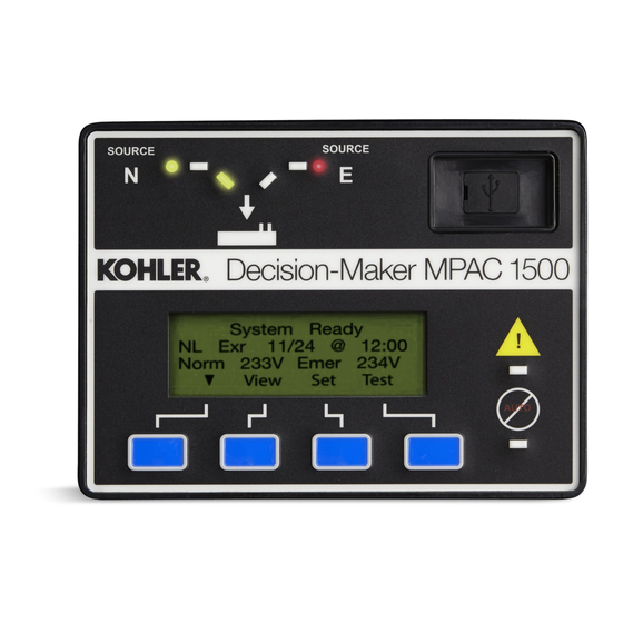
- Page 1 Operation Automatic Transfer and Bypass/Isolation Switches Controls: MPACt 1500 Software (Code) Version 2.0 or higher TP-6714 4/10a...
-
Page 3: Table Of Contents
Table of Contents Safety Precautions and Instructions ............Introduction . - Page 4 Table of Contents, continued Sequence of Operation, Closed Transition Models ......3.9.1 Preferred Source Loss and Return, Closed-Transition .
- Page 5 Table of Contents, continued Exerciser ............. 5.7.1 Setting the Exerciser .
- Page 6 Table of Contents, continued Connections ............6.2.1 Serial Connections .
-
Page 7: Safety Precautions And Instructions
Safety Precautions and Instructions IMPORTANT SAFETY INSTRUCTIONS. Accidental Starting DANGER Electromechanical equipment, including generator sets, transfer WARNING switches, switchgear, accessories, can cause bodily harm and pose life-threatening danger when improperly installed, operated, or Hazardous voltage. maintained. To prevent accidents be Will cause severe injury or death. - Page 8 Short circuits. Hazardous allow the transfer switch to continue to Notice voltage/current can cause severe supply power to the load. Disconnect injury or death. Short circuits can all power sources to accessories that NOTICE cause bodily injury and/or equipment are mounted within the enclosure but Hardware damage.
-
Page 9: Introduction
Information in this publication represents data available at the time of print. Kohler Co. reserves the right to The equipment service requirements are very important change this literature and the products represented to safe and efficient operation. Inspect parts often and without notice and without any obligation or liability perform required service at the prescribed intervals. -
Page 10: Service Assistance
Visit the Kohler Power Systems website at Phone: (86) 21 6288 0500 KohlerPower.com. Fax: (86) 21 6288 0550 Look at the labels and stickers on your Kohler product India, Bangladesh, Sri Lanka or review the appropriate literature or documents India Regional Office included with the product. -
Page 11: Section 1 Installation
Section 1 Installation This section contains instructions for controller connections. For ATS installation instructions, refer to the transfer switch installation manual supplied with the transfer switch. Controller Connections DANGER Hazardous voltage. Will cause severe injury or death. Disconnect all power sources before opening the enclosure. -
Page 12: Logic Board Input And Output Connections
1.1.1 Logic Board Input and Output 1.1.2 Communication Connections Connections See Section 6 for instructions to connect to the controller’s RS-485 serial port or Ethernet port for Logic board terminal strip TB1 has two programmable Modbus communication. See Section 6.4 for inputs and two programmable outputs. -
Page 13: Extended Transfer Time Relay
Extended Transfer Time Relay Accessory Connections The extended transfer time relay is provided on See Section 8 and the transfer switch wiring diagrams closed-transition transfer switches. The relay is for accessory connection instructions. provided to prevent paralleling the standby and utility sources for longer than the acceptable time if the Controller Powerup/Reset closed-transition transfer time exceeds 100 ms. -
Page 14: System Setup
System Setup Functional Tests Set the controller’s current time and date. Perform the functional tests described in the transfer Section 5.6 for instructions. switch Installation Manual and in Section 2 of this manual before putting the transfer switch into operation. The transfer switch is factory-set with default settings for time delays and other parameters. -
Page 15: Section 2 Operation Tests
Section 2 Operation Tests Introduction Lamp Test Be sure to perform the functional tests described in the To test the LEDs on the controller’s user interface, go to transfer switch Installation Manual and in this section the Main screen. Press the down arrow button once, before putting the transfer switch into operation. - Page 16 Note: If the standby source fails during a loaded test, transition transfer. If automatic override is not the ATS will immediately attempt to transfer to the enabled, the ATS will continue to monitor the preferred source. source synchronization and transfer when/if the sources synchronize.
- Page 17 System OK On the main screen, press the Test button. LD Exer ##/## @ ##:## Norm ###V Emer ###V View Test Use the open arrow buttons to enter the Test Enter Password Time to Enter #:## password. See Section 3.4 for instructions. Then >...
- Page 18 Notes Section 2 Operation Tests TP-6714 4/10...
-
Page 19: Section 3 Operation
Section 3 Operation Introduction 3.2.1 Display The four-line display indicates transfer switch status and This section contains operation instructions, including: setup, including the following: User interface panel, with display, pushbuttons, and System status LED indicators Faults and warnings Main screen Active time delays System status, warnings, and faults Source voltages... -
Page 20: Led Indicators
3.2.2 LED Indicators Down arrow (closed). Step down to the next LEDs on the user interface indicate contactor position, screen or scroll through a list. source availability, faults, and other conditions. The Up arrow (closed). Step back to the previous table in Figure 3-2 describes the functions of the LED screen. - Page 21 System OK Set Time LD Exer ##/## @ ##:## Norm ###V Emer ###V " Back View Test Press the SET button. Press the right arrow button to enter the Set Time submenu. Enter Password Time to Enter #:## ? ? ? ? Set Time ##:## Back Save...
- Page 22 Set Common Alarms Set Common Alarms Alarm Description Alarm Description Modify Alarm Alarm Group 1 Common Audible Common Y Audible N " " " Main Back Back " Back Back Save Press the up and down Press the up arrow arrow buttons to step button to step through Press the up and...
-
Page 23: Main Screen
Main Screen Press the Test button to enter the Test mode. password is required. See Section 3.10. The main screen appears at system startup and The display returns to the main screen after 30 minutes displays the following information (see Figure 3-6): of no activity (no buttons pressed). -
Page 24: Passwords
Passwords 3.4.3 Test Password Reset and Disable The test password can be reset to the default value or Passwords are required to enter the Test and Setup disabled. Use the Setup Menu--Reset Data screen. See screens. Passwords are 4-digit numbers. Figure 3-25. -
Page 25: Normal Operation Screens
Normal Operation Screens System Ready During normal transfer switch operation, the screens LD Exer 12/14 @ 16:00 shown in Figure 3-9 or Figure 3-10 are displayed. Use Norm 480V Emer 480V the up and down arrow buttons to view the system status View Test information as shown. -
Page 26: Sequence Of Operation, Standard Transition
Sequence of Operation, 3.6.2 Exerciser Operation, Standard Transition Standard Transition The Sequence of Operation descriptions in Sections 3.6 Unloaded Exercise Sequence Starts through 3.9 describe the transfer switch normal 1. Exerciser timer begins. operation for standard, programmed, and closed transition models, and for service entrance models. 2. -
Page 27: Test Sequence
Loaded Exercise Sequence Ends Emergency Source Fails (Normal Source is available) 1. Pre-transfer load control sequences run. 1. Test function is deactivated. 2. Load control contacts open. 2. Load control contacts open. 3. Contactor transfers to preferred. 3. Contactor immediately transfers to preferred. 4. -
Page 28: Sequence Of Operation, Programmed-Transition
Sequence of Operation, 3.7.2 Exerciser Operation, Programmed Transition Programmed-Transition Programmed-transition models operate with a pause in Unloaded Exercise the off position during transfer. The time in the off The unloaded exercise sequence is the same as for position is set through the off-to-standby and standard transition. -
Page 29: Test Sequence, Programmed-Transition
Loaded Exercise Sequence Ends Emergency Source Fails (Normal Source is available) 1. Pre-transfer load control sequences run. 1. Test function is deactivated. 2. Load control contacts open. 2. Immediate failure to acquire standby alarm. 3. Contactor transfers to Off position. 3. -
Page 30: Sequence Of Operation, Service Entrance Models
Sequence of Operation, 3.8.2 Exerciser Operation, Service Entrance Models Service Entrance Models Service entrance models operate in programmed- Unloaded Exercise transition mode, with a pause in the off position during The unloaded exercise sequence is the same as for transfer. The time in the off position is set through the standard transition. -
Page 31: Test Sequence
Loaded Exercise Sequence Ends Emergency Source Fails (Normal Source is available) 1. Pre-transfer load control sequences run. 1. Test function is deactivated. 2. Load control contacts open. 2. Immediate failure to acquire standby alarm. 3. Source 2 circuit breaker opens. 3. -
Page 32: Sequence Of Operation, Closed Transition Models
Sequence of Operation, Note: If the standby source contacts do not open within 100 ms, the extended transfer time Closed-Transition Models relay trips the standby source breaker. Closed-transition transfer switches operate with no 6. Post-transfer load control sequences and engine interruption of power to the load during transfer when cooldown time delay expire. -
Page 33: Exerciser Operation, Closed-Transition
4. Standby source contacts open. Note: If the sources do not synchronize before the Fail to Sync time delay expires, the 5. Off-to-preferred time delay runs and expires. programmed-transition override function operates. See Section 3.9.2. 6. Preferred source contacts close. 4. - Page 34 Loaded Test Sequence is Ended 5. Standby source contacts open within 100 milliseconds. 1. Standby-to-preferred and pre-transfer load control time delays expire. Note: If the standby source contacts do not open within 100 ms, the extended transfer time 2. Load control contacts open according to the Load relay trips the standby source breaker.
-
Page 35: System Test
3.10 System Test Figure 3-12 shows the screens displayed during the test run. Screens are dependent on the system settings and Use the system test feature to: time delays. See Figure 3-15 for Sync Check screens for closed-transition models. Start and run the generator set. Press the End Test designated pushbutton to end the Simulate a preferred source failure, resulting in a test. -
Page 36: Unloaded System Test
3.10.1 Unloaded System Test Engine Start in ##:## Norm ###V Emer ###V When an unloaded test is initiated, the controller immediately signals the generator to start, without waiting for the engine start time delay to expire. The Main Delay Test contactor does not change position during an unloaded LD# Disc in ##:## test, but if the normal source should fail, the contactor... -
Page 37: Auto-Loaded System Test
If the sources do not sync before the Fail to Sync time 3.10.5 Sync Check (closed-transition) delay expires, the programmed-transition override The Sync Check allows a test of the synchronization of function operates. two available sources without initiating a transfer. If the override function is set to Automatic, a Navigate to the Type of Test, Sync Check menu and programmed-transition transfer will occur when the... -
Page 38: Lamp Test
3.11 Lamp Test the enable/disable setting in the Set Exercise screens. See Section 5.7. To test the LEDs on the controller’s user interface, go to the Main screen. Press the down arrow button once, 3.12.1 Unloaded Exercise then press the Lamp Test button and verify that the LCD screen and all 6 LEDs on the user interface illuminate. -
Page 39: Warnings And Faults
3.13 Warnings and Faults ATS warnings and faults are shown in Figure 3-19. There are three types of warning/fault conditions: When a fault exists, the System Alert indicator flashes, a Warning. Warnings automatically reset with a source designated output and the common fault output are availability change or a transfer request. -
Page 40: Fault Reset
3.13.1 Fault Reset Module Status Change To clear a fault or warning condition and reset the Press Reset. Norm ###V Emer ###V System Alert LED, go to the Main screen and press the Reset View Set Test down arrow button to open the Reset screen. See Figure 3-18 and Figure 3-20. -
Page 41: Module Status Conflict
Module Uninstall Procedure 3.14.2 Module Status Conflict 1. Press Main to return to the main screen. The message Module Status Conflict appears if one type of module is replaced with another type of module 2. Press Set to enter setup mode. that has the same address. -
Page 42: Reset Data
3.15 Reset Data 3.15.2 Reset Event History Resetting the event history clears the events from the Be sure to read and understand the information in this event history log. The history lists the 100 most recent section before resetting records or parameters. transfer switch events, including transfers and DIP Note: Resetting to the default parameters will reset all switch setting changes as well as faults and alarms. - Page 43 Reset Reset Data Maintenance Records Yes/No " Save Back Main Reset Event History Yes/No Save Back Reset Note: Resetting to the default parameters will reset all Default Parameters parameters, including the system voltage Yes/No and frequency, to a factory default setting. The Save Back transfer switch will not operate correctly if the system voltage and frequency do not match the...
-
Page 44: Reset And Disable Test Password
3.15.4 Reset and Disable Test Password command to ensure that the most recent events are included before transferring the file to a mass storage Reset the Test password to return the test password to device, if desired. the default, 0000. Event history files have filenames of the form Disable the test password to allow the user to start a test presentyymmdd.his, where yymmdd (year, month, day) -
Page 45: Section 4 View Screens
Section 4 View Screens Introduction View Screens This section illustrates the view screens. Use the view From the main screen, press the View button to step to screens to check system settings, event history, and the first view screen, View Event History. maintenance records. -
Page 46: View Event History
View Event History View Maintenance Records The Event History screens show recent transfer switch events. Examples of events recorded in the event View View Maintenance Maintenance Records Maintenance Item history are shown in Figure 4-2. Events are time- and ####### date-stamped. -
Page 47: View Exerciser Setup
View Exerciser Setup View System Setup System Setup View Start date and time System Setup Standard Transition Exercise event number Run time Util-Gen Operation " Main Back Ex#?? Disabled HH:MM View System Setup Start MM/DD @ HH:MM Exerciser Setup Standard Transition Service Entrance Weekly Unloaded... -
Page 48: View Source Setup
View Source Setup View View Source Setup Source Setup ABC Rotation " Back Main View Source Setup Norm 120V Emer 120V 60 Hz 60 Hz Back View Source Setup View Source Setup View Source Setup Normal Over Voltage Normal Under Voltage PU 95% DO 115% PU 90% DO 90% Debounce 0.5S... - Page 49 Continued from previous page View Source Setup View Source Setup View Source Setup In Phase Monitor In Phase Monitor In Phase Monitor Enabled/Disabled Angle XX Degrees " " Back Back Back Standard Transition Only View Source Setup View Source Setup View Source Setup In Phase Xfer Fail In Phase Xfer Fail...
-
Page 50: View Time Delays, Source 1
4.10 View Time Delays, Source 1 View View S1 Time Delays Source1 Time Delays Engine Start ##:## " Main Back View S1 Time Delays Engine Cooldown ##:## Back View S1 Time Delays Xfr Pref > Stby ##:## Back View S1 Time Delays Xfr Off >... - Page 51 View Time Delays, Source 1, Continued Current-based load control screens, continued from Source 1 time delay screens. Current-Based Contrl View S1 Time Delays Load ## Disc N>E Current-Based Contrl ##:## Load Disc N>E " Back Back Current-Based Contrl Current-Based Contrl View S1 Time Delays Load # Add Source1 Load Ctrl # Source1...
-
Page 52: View Time Delays, Source 2
4.11 View Time Delays, Source 2 View View S2 Time Delays Source2 Time Delays Engine Start ##:## " Main Back View S2 Time Delays Engine Cooldown ##:## Back View S2 Time Delays Xfr Stby > Pref ##:## Back View S2 Time Delays Xfr Off >... - Page 53 View Time Delays, Source 2, Continued Current-based load control screens, continued from Source 2 time delay screens. Current-Based Contrl View S2 Time Delays Load ## Disc E>N Current-Based Contrl ##:## Load Disc E>N " Back Back Current-Based Contrl Current-Based Contrl View S2 Time Delays Load # Add Source2 Load Ctrl # Source2...
-
Page 54: View Inputs/Outputs
4.12 View Inputs/Outputs View View Main Board I/O Inputs/Outputs Main Board I/O Input ## Function Description " " Main Back Back Main Board I/O Output ## Function Description Back View Module #1 Module #1 Auxiliary I/O Type ### Addr 1 Input ## Status: OK Function Description... -
Page 55: View Communications Setup
4.14 View Communications Setup 4.15 View Control Parameters View Control Parameters View View Comm Setup Control Parameters Code Version: Communications Setup MODBUS Server TCP Enabled/Disabled " Main Back " Back Main Control Parameters View Comm Setup ATS Serial Number: MODBUS Server Port # ####### Enabled/Disabled Back... - Page 56 Notes Section 4 View Screens TP-6714 4/10...
-
Page 57: Section 5 Setup
Section 5 Setup Introduction The test password is not affected by this DIP switch. Use the Reset Data screen to disable the test password. This section contains setup instructions, including: SW1-2, Maintenance. The maintenance DIP switch Controller DIP switch settings inhibits transfer. -
Page 58: Default Settings And Time Delays
Default Settings and Time 5.4.2 Time Delays Delays The factory settings for the time delays are shown in Figure 5-10. The system can be operated using the factory settings listed in the following sections. The pre-transfer time delays operate only when both sources are available. -
Page 59: Setup Screens
Setup Screens After entering the system password, use the black arrow keys to step through the setup screens as shown in From the main operation window, press the Set button to Figure 5-5. enter the setup screens. Timeout. After 10 minutes of no activity (no buttons The setup password is required. -
Page 60: Time/Date
Time/Date Set the current time and date. The time and date are used by the exercise function and event history Note: Set the current time and date after transfer switch functions. installation or after an extended period of no The Time/Date setup screen includes the option to power. -
Page 61: Exerciser
Exerciser 5.7.2 Source/Source Mode In the Util-Gen mode, the exercise function occurs on The exerciser uses a calendar-based scheduling the standby source. In Gen-Gen mode, the standby system. Up to 21 different exercise events can be source generator set is exercised. scheduled, each with different settings. - Page 62 Exercise Event ## Exerciser Event ## Set Exerciser Exerciser Event ## Loaded/Unloaded Enable/Disable Back Next " " Back Next Back Main Exerciser Event ## Exerciser Event ## Exerciser Event ## Exerciser Event ## Interval ??????? Repeat Rate ?? Start Date ??/??/?? Duration HH:MM Back Next...
-
Page 63: Prime Power Run
Prime Power Run generator duration times days:hours:minutes (i.e. how long each generator set The transfer switch can be used between two prime runs before transfer to the other generator set). See power sources (two generator sets). The prime power Figure 5-9. run feature allows the controller to sequence the usage In the Prime Power Event screen, use the up arrow of each generator set to equalize the run times. -
Page 64: Time Delays
Time Delays transfers. The pre-transfer signals are active only when both sources are available. The pre-transfer signals overlap the transfer time delays (Xfr N>E and E>N). 5.9.1 Time Delays The longer delay determines the time delay before transfer. Up to nine loads can be controlled with The factory settings and adjustment ranges for the time independent timing sequences for pre- and post- delays are shown in Figure 5-10. -
Page 65: Set S1 Time Delays
5.9.3 Set S1 Time Delays Engine Start External Battery Set S1 Time Delays ?? : ?? Yes/No Set S1 Time Delays Engine Start " " " Main Back Back Save Back Save Set S1 Time Delays Eng Cooldown Eng Cooldown ??:?? "... - Page 66 Current-Based Load Control Menus Continued from Previous Page: Set S1 Time Delays Set S1 Time Delays Load #? Disc N>E Current-Based Control Current-Based Control ??:?? Load Disc N>E Load #? Disc N>E " " Back Back Back Save Current-Based Control Current-Based Control Load #? Add Source1 Load Control Source1...
-
Page 67: Set S2 Time Delays
5.9.4 Set S2 Time Delays Engine Start External Battery Set S2 Time Delays ?? : ?? Yes/No Set S2 Time Delays Engine Start " " " Main Back Back Save Back Save Set S2 Time Delays Eng Cooldown Eng Cooldown ??:?? "... - Page 68 Current-Based Load Control Menus Continued from Previous Page: Set S2 Time Delays Set S2 Time Delays Load #? Disc E>N Current-Based Control Current-Based Control ??:?? Load Disc E>N Load #? Disc E>N " " Back Back Back Save Current-Based Control Current-Based Control Load #? Add Source2 Load Control Source2...
-
Page 69: Load Control
5.10 Load Control Time-Based Load Control Setup Setting up the load control function requires the The controller allows control of up to 9 separate loads. following steps: Two load control modes allow selected loads to be disconnected and reconnected to the source: 1. - Page 70 8. Enter the number of loads to control, which is equal b. Load # Rec N>E: post-transfer time delay to the number of loads connected to outputs in reconnects loads a programmed time after step 1. transfer to Emergency. The post-transfer time delay allows delayed or staggered addition of 9.
-
Page 71: Current-Based Load Control
5.10.2 Current-Based Load Control 4. Enter the number of loads to control, which is equal to the number of loads connected to outputs in Current-based load control allows the addition and step 1. removal of loads based on the measured current through the transfer switch. - Page 72 Parameter Description Adjustment Range Assign Load Control Out # to each connected load output. Use Outputs the Set Inputs/Outputs menu. See Section 5.12, programmable Load Control Out 1--9 Inputs and outputs. Select Current for current-based load control. See Section Load Control Mode None/Time/Current 5.10.2 for more information.
-
Page 73: Source Setup
5.11 Source Setup Adjustment Range Parameter Default Setting Voltage 5.11.1 Phase Rotation 0--5% Differential The Phase Rotation menu appears only if a three-phase Frequency 0--0.3 Hz 0.1 Hz source is selected. (See Set Number of Phases later in Differential the Set Sources menus for the Normal and Emergency Angle 0--10 degrees 10 degrees... -
Page 74: System Voltage And Frequency
Use the Set System, Source type screen to change the Note: Source N is always connected to the Normal side of the transfer switch, and Source E is always source types to generator set-generator set or connected to the Emergency side. utility-utility if necessary. -
Page 75: Voltage And Frequency Pickup And Dropout Settings
5.11.5 Voltage and Frequency Pickup dips. If the voltage or frequency of the active source is outside the acceptable range for a length of time longer and Dropout Settings than the debounce time, the system attempts to transfer The controller senses the voltage on both sources with the load to the alternate source. -
Page 76: Set Sources
5.11.6 Set Sources Three-phase models only. ? ? ? Rotation Set Sources Set Phase Rotation Disable " " Main Back Save Back Set Inphase Monitor Enable/Disable Enable/Disable " Back Save Back Set Inphase Monitor ? ? Degrees Angle Standard transition models only "... - Page 77 Set Sources, continued Source Setup Screens Continued from Previous Page: Normal Source Set Normal Source ? Phase Set Number of Phases Emergency " Back " Back Save Back Set Voltage Normal Source Note: The same menus are available ??? VAC Set Voltage for the Emergency source.
- Page 78 Set Sources, continued Source Setup Screens Continued from Previous Page: Dropout Normal Source Voltage Unbalance 5--20% Dropout " Save Back Back Pickup Normal Source ??? % of Nominal Set Under Frequency 80--95% Pickup " Save Back Back Dropout Normal Source ??? % of Pickup Set Under Frequency 95--99%...
-
Page 79: Programmable Inputs And Outputs
5.12 Programmable Inputs and 5.12.1 Main Logic Board Inputs and Outputs Outputs There are two programmable inputs and two Inputs and outputs are unassigned (except as noted in programmable outputs on the controller’s main logic Figure 5-17) until the installer or operator assigns a board. -
Page 80: Input Functions
5.12.3 Input Functions Remote Monitored Inputs. There are four remotely monitored input functions. These functions can be Available input functions are shown in Figure 5-18. assigned to any of the inputs on either the main logic Some inputs will trigger an indicator LED on the user board or standard/high voltage/high current I/O boards. -
Page 81: Output Functions
5.12.4 Output Functions Section Programmable Output Type Output functions are shown in Figure 5-19. Information 3 Src Sys Disabled Control 5.15 about selected output functions is shown below. Refer Alarm Silenced Monitor to the section number shown in Figure 5-19 for more Audible Alarm Control information about the output function. -
Page 82: User-Defined I/O Function Descriptions
Load Bank Control Active. The load bank control 5.12.5 User-Defined I/O Function output is a C form contact that can be used to apply a Descriptions load to the generator set during an unloaded exercise or test. The load bank control output is active during each The controller can store a 19-character string unloaded test and unloaded exercise. -
Page 83: Common Alarms
System Ready The Chicago alarm function is a programmable feature External Battery Low *[ Test Mode Active of the MPAC 1500 controller. The alarm is active when Non-Emergency Trans Critical Service Required the transfer switch is in the Emergency position. The... -
Page 84: Set System
5.14 Set System Programmed-transition override (for closed- transition models only). When closed transition is selected, the programmed-transition override menu 5.14.1 Source Type/Source Type appears. The override function operates if the sources do not synchronize before the Inphase Transfer Fail Set the source type selection for the types of sources time delay expires. -
Page 85: Remote Test Loading
Setting this function to Commit allows the complete 5.14.9 USB Data Logger transfer sequence to execute even if the preferred The controller can transfer and save time-stamped source returns before the load has been transferred readings of voltage, frequency and phase angle for both to standby. - Page 86 * Source Types: Util-Gen Set System Source Type Source Type Gen-Gen ?????? -- ?????? Util-Util " " Util-Gen-Gen Back Back Save Main ** Transition Types: Transition Type Transition Type Prog Transition Override Standard Transition ???????? Automatic/Manual Programmed Transition " Closed Transition Back "...
-
Page 87: Three-Source Systems
5.15 Three-Source Systems 5.15.3 Three Source System Test and Exercise A three-source system provides the means to connect a utility and two generators to a single load. Unloaded Test Figure 5-27. Two generators and two transfer switches are required. Unloaded testing is possible at each transfer switch. Initiating the unloaded test function at ATS1 starts and Note: The second transfer switch (ATS2) requires an runs the preferred generator set attached to ATS2. -
Page 88: Ats1 And Ats2 System Setup
c. Connect the emergency side of ATS1 to the marking on the board for the positive (+) and load side of ATS2. negative (--) connections. See Figure 8-14 and Figure 8-15. d. Connect generator set 1 to the normal side of ATS2. - Page 89 SINGLE LINE DIAGRAM ATS2 ATS1 ENGINE START TO G2 NOTE: THE CLOSED IN EMERGENCY AUXILLIARY ENGINE START CONTACT THAT IS USED IN THE ENGINE START CIRCUIT OF THE ATS MUST BE REMOVED FROM THE CIRCUIT WHEN USED WITH THIS THREE SOURCE CONTROL SCHEME. REFERENCE ATS WIRING DIAGRAM FOR CONNECTIONS.
- Page 90 ATS1 3 Source System Disable Connect Output 1 terminals TB1-5 and TB1-6 on ATS 1 to Input 1 terminals TB1-1 and TB1-2 on ATS2. Assign ATS 1 main logic board output 1 to 3 Source System ATS1 TB1 Disable. on logic board Assign ATS2 main logic board ATS2 input 1 to 3 Source System...
-
Page 91: Communications
5.16 Communications 5.17 Set Passwords Use the communications setup screen to set the Two passwords control access to the Test and Setup communication parameters for serial or ethernet screens. Passwords are 4-digit numerical values connections. See Section 6, Communications, for ranging from 0000 to 9999. -
Page 92: Calibration
5.18 Calibration The transfer switch voltage and current sensing (if equipped) are calibrated at the factory. If voltage DANGER recalibration is necessary, refer to the Test Section for instructions to check the voltages. and then use the Setup Screen--Calibration to enter the measured values. -
Page 93: Section 6 Communications
Section 6 Communications Introduction Connections The MPACt 1500 controller has three types of See Figure 6-1 for the connector locations. communications connections: an RS-485 serial port, an ethernet port, and a USB port. Use Ethernet or serial connections to connect the transfer switch to a personal computer for system monitoring and control using Kohlerr Monitor III software or other Modbus applications. -
Page 94: Serial Connections
6.2.1 Serial Connections The serial port is an isolated RS-485 port with connection speeds of 9.6, 19.2, and 57.6 kbps. Use Use serial connections to TB2 on the controller’s logic shielded twisted-pair cable to connect to the RS-485 board to connect the transfer switch to a personal connectors on the main logic board terminal strip TB2 for computer, the optional ATS remote annunciator, or a serial connections. -
Page 95: Ethernet Connections
6.2.2 Ethernet Connections Figure 6-4. Change the IP address to an address owned by the user. See Section 5.16 for instructions to The transfer switch can be connected to a building’s set the communication parameters. ethernet network to communicate with personal computers connected to the same subnet. - Page 96 ATS 1500 Controller IP xx.xx.xx.03 Modbusr TCP/IP Category 5e Ethernet Modbusr Network TCP/IP Modbusr TCP/IP Modbusr PC with network Category 5e interface card RS-485 IP xx.xx.xx.02 Device Device Converter, Modbusr Modbusr/Ethernet TCP/IP RS-485 RS-485 IP xx.xx.xx.05 Device Device RS-485 PC with network interface card Last device IP xx.xx.xx.01...
-
Page 97: Communications Setup
Communications Setup connections. See Figure 6-6. The controller uses Modbusr communication protocol. Use the communications setup screen to set the communication parameters for serial or ethernet MODBUS Server TCP Communications Setup Communications Setup Enabled/Disabled MODBUS Server TCP " " Back Save Main Back... -
Page 98: Serial Communication
6.3.1 Serial Communication Modbus Address. Assign a unique Modbus address to each device on the network. Monitor III software Set the following communication parameters for serial requires a unique Modbus address to identify the communication. Also see Figure 6-7. controller. Record the address to enter into Monitor III software. -
Page 99: Usb Port
USB Port Sections 6.4.2 through 6.4.4 contain more information about specific file types. See Section 3.15.5 for The Universal Serial Bus (USB) port on the main logic additional information about controller file maintenance. board allows file transfer to and from a USB mass storage device (removeable flash drive). -
Page 100: File Transfer
6.4.1 File Transfer Upload button to load files from the controller through the USB port to a memory device. The USB Access screen opens automatically when a device is connected to the controller’s USB port. See 3. Use the down button to scroll through the list of Figure 6-10. -
Page 101: Event History Files
6.4.2 Event History Files 6.4.3 Configuration files The event history files can be opened with spreadsheet The configuration (.cfg) file contains the transfer switch software. Event history files have filenames of the form settings, including: presentyymmdd.his, where yymmdd (year, month, day) System setup is the date of the file as read from the controller. -
Page 102: Data Logger Files
6.4.5 Data Logger Files 6.4.6 MinMax Files Data log files are generated by the USB Data Logger MinMax files are generated by the MinMax function and function. The data log files can be opened with can be opened with spreadsheet software. The file spreadsheet software. -
Page 103: Section 7 Scheduled Maintenance
Section 7 Scheduled Maintenance Introduction DANGER Regular preventive maintenance ensures safe and reliable operation and extends the life of the transfer switch. Preventive maintenance includes periodic testing, cleaning, inspection, and replacement of worn Hazardous voltage. or missing components. Section 7.4 contains a service Will cause severe injury or death. -
Page 104: Testing
Servicing the transfer switch. Hazardous voltage can Testing cause severe injury or death. Deenergize all power sources before servicing. Turn off the main circuit breakers of all 7.2.1 Weekly Generator Set Exercise transfer switch power sources and disable all generator sets as follows: (1) Move all generator set master controller Use the exerciser to start and run the generator set switches to the OFF position. -
Page 105: Other Inspections And Service
Tighten loose external hardware. Replace any worn, Signs overheating loose connections: missing, broken external components with discoloration of metal, melted plastic, or a burning manufacturer-recommended replacement parts. odor Contact a local authorized distributor/dealer for specific Other evidence of wear, damage, deterioration, or part information and ordering. -
Page 106: Service Schedule
Service Schedule Follow service schedule below recommended service intervals. Have all service performed by an authorized distributor/dealer except for activities designated by an X, which may be performed by the switch operator. Adjust, Visually Repair, Section Inspect System Component or Procedure Check Replace Clean... -
Page 107: Section 8 Accessories
Section 8 Accessories Introduction Accessory Module Mounting This section describes the hardware options that will Mount the accessory modules on the module mounting interface with the MPACt 1500 controls. The following plate. Starting at the end of the module mounting accessories are available: assembly nearest the cable connection, install any I/O modules first, then install the alarm board, if used. -
Page 108: Input/Output (I/O) Modules
Input/Output (I/O) Modules Use 14-24 AWG cable to connect to input and outputs. Each output is a form C SPDT contact. Two types of input/output modules are available. The LEDs on the module circuit board light to indicate that standard I/O Module has two inputs and six outputs. each input or output is active. -
Page 109: Alarm Module
Alarm Module The functions provided by this board are: 90 dB Audible alarm (any alarm function can be programmed to trigger the audible alarm) Chicago alarm operation Preferred source selection Supervised transfer control (supervised transfer control switch required) Connection for external alarm The alarm board is equipped with a 90 dB audible alarm. -
Page 110: Alarm Board Dip Switches
8.5.1 Alarm Board DIP Switches Alarm Operation: Chicago Alarm Mode Chicago Alarm mode requires the horn to sound and a There are four DIP switches on the alarm module board. lamp or LED to light when the switch is in the emergency Two of the switches are not used at this time. -
Page 111: External Battery Supply Module (Ebsm)
External Battery Supply The external battery supply module kit includes one external battery supply circuit board and the circuit Module (EBSM) board mounting components. See Figure 8-14. The external battery supply module kit allows A module mounting kit is required for installation of the connection to the generator set engine start battery(ies) external battery supply module. -
Page 112: Heater
Heater An anti-condensation heater kit is available. The strip heater is controlled by a hygrostat to raise the temperature inside the enclosure above the dew point to prevent condensation. Figure 8-17 shows a typical location of the heater kit components inside the enclosure. -
Page 113: Transient Voltage Surge Suppressor (Tvss)
Transient Voltage Surge Note: All leads must be connected and power applied for the LEDs to illuminate. Suppressor (TVSS) If the red indicator is on, the TVSS no longer provides A transient voltage surge suppressor (TVSS) is protection. Replace the TVSS module. available for the transfer switch. -
Page 114: Tvss Replacement
contact terminals on terminal block TB1. b. Disconnect power to the battery charger. Figure 8-23 for the contact rating and Figure 8-22 for the c. Disconnect the generator set engine starting terminal block location. See the decal on the TVSS battery, negative (--) lead first. - Page 115 Figure 8-24 TVSS Wiring Diagram, GM71341 TP-6714 4/10 Section 8 Accessories...
-
Page 116: Supervised Transfer Control Switch
Supervised Transfer Control Automatic and Non-Automatic Transfer Switches. The switch operation differs for automatic and Switch non-automatic switches. An automatic transfer switch transfers automatically to an available source if the The supervised transfer control switch (AUTO/ connected source is lost. A non-automatic transfer MANUAL/TRANSFER switch) is a three-position, key- switch does not transfer automatically, even if the operated switch that allows manual control of load... - Page 117 Switch Position Operation, Automatic Switches Operation, Non-Automatic Switches D Automatically transfers to the standby source, when available, if the preferred source is lost AUTO D Transfers back to the preferred source when it becomes available D Automatically transfers to an available source if the D Enables the Not-in-Auto indicator MANUAL connected source is lost...
-
Page 118: Current Sensing
8.10 Current Sensing Current transformer kits are designed for your transfer switch based on the current rating, number of phases, The current sensing kit uses current transformers to and transfer switch model. measure the load bus current on all phases. Load Use a clamp-on current sensing meter to calibrate the current can then be displayed on the controller screen. - Page 119 Figure 8-28 Current Sensing Wiring Diagram TP-6714 4/10 Section 8 Accessories...
-
Page 120: Load Shed (Forced Transfer To Off)
8.11 Load Shed Source N. If Source N is not available, the ATS remains in the Off position until the input is deactivated. When (Forced Transfer to OFF) the input is deactivated, the ATS transfers back to Source N, if available, executing all programmed time The load shed (forced transfer to OFF) accessory must delays. -
Page 121: User Interface Cover
8.12 User Interface Cover The gasket-sealed, hinged user interface cover prevents unauthorized access to the transfer switch controls and protects the user interface from harsh environmental conditions. Use a customer-supplied padlock to lock the cover. The cover is available with or without a window for NEMA 1 enclosures. -
Page 122: Logic Disconnect Switch
8.14 Logic Disconnect Switch The switch has two positions, auto and disconnect. The disconnect position disconnects the voltage sensing leads for normal and emergency (A, B, C, N) and the WARNING engine start signal. Note: Disable the generator set before using the logic disconnect switch to disconnect power to the ATS controls. -
Page 123: Appendix A Abbreviations
(2 bytes) est. estimated Canadian Electrical Code KBus Kohler communication protocol E-Stop emergency stop cert. certificate, certification, certified kilogram etc. et cetera (and so forth) cubic feet per hour TP-6714 4/10... - Page 124 kg/cm kilograms per square National Bureau of Standards remote terminal unit centimeter normally closed room temperature vulcanization kilogram-meter National Electrical Code read/write kg/m kilograms per cubic meter NEMA National Electrical Society of Automotive kilohertz Manufacturers Association Engineers kilojoule NFPA National Fire Protection scfm standard cubic feet per minute Association...
-
Page 125: Appendix B Screen Summaries
Appendix B Screen Summaries For reference, this section lists the items displayed during normal operation, and the information and settings shown in the View and Setup screens. Operation Screens View Screens Main Screen Main Screen System Status System Status Next Exercise Time and Date Next Exercise Time and Date Normal and Emergency Voltage Normal and Emergency Voltage... - Page 126 View Exerciser Setup View Source Setup, Continued Exercise Event Number Synchronization (for closed-transition) Enabled/Disabled Voltage Differential Exercise Run Time Frequency Differential Start Date Angle differential Start Time Fail toSync Weekly/Biweekly Enabled/Disabled Loaded/Unloaded Time Delay min:sec View System Setup View Time Delays, Source S1 and Source S2 Open/Programmed/Closed Transition Engine Start (gen set only) Source Type: Util/Gen, Gen/Gen, Util/Util or Util/Gen/Gen...
- Page 127 View Communications Setup View Control Parameters Modbus Server TCP Enabled/Disabled Code Version (factory-set) Modbus Server Port 1 and 2 ATS Serial Number (factory-set) Enable/Disabled Controller Serial Number (factory-set) Modbus Address Port 1 and 2 Contactor Serial Number (factory-set) Baud Rate Port 1 and 2 Site Designation (optional;...
- Page 128 Setup Screens Set Source Phase Rotation ABC/BAC/Disabled Set Time/Date Set In-Phase Monitor Set Time Enable/Disable Set Date Angle Set Automatic Daylight Saving Time In-Phase Transfer Fail Time Delay Set Exerciser Enable/Disable For each exerciser event: Time Delay min:sec Enable/Disable Set Synchronization Loaded/Unloaded Voltage Differential Interval...
- Page 129 Set System Set Passwords Source Type: Utility/Generator, Generator/Generator, Setup Password Utility/Utility, Utility/Generator/Generator (3--source system) Test Password Transition Type: Standard/Programmed/Closed Calibration Prog Transition Override Automatic/Manual Line-Neutral Voltages, Source N and E (closed-transition only) Line-Line Voltages, Source N and E Service Entrance No/ICCB/MCCB Load Current, LA, LB, and LC Rated Current, Amps Reset Data...
- Page 130 Notes 130 Appendix TP-6714 4/10...
- Page 132 For the nearest sales/service outlet in the US and Canada, phone 1-800-544-2444 KohlerPower.com Kohler Power Systems Asia Pacific Headquarters TP-6714 4/10a 7 Jurong Pier Road Singapore 619159 E 2009, 2010 by Kohler Co. All rights reserved. Phone (65) 6264-6422, Fax (65) 6264-6455...
Need help?
Do you have a question about the MPAC 1500 and is the answer not in the manual?
Questions and answers