Sign In
Upload
Manuals
Brands
Kohler Manuals
Controller
Decision-Maker 3000
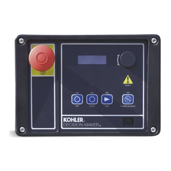
Kohler Decision-Maker 3000 Controller Manuals
Manuals and User Guides for Kohler Decision-Maker 3000 Controller. We have
3
Kohler Decision-Maker 3000 Controller manuals available for free PDF download: Manual, Operation
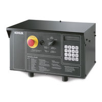
Kohler Decision-Maker 3000 Manual (224 pages)
Industrial Generator Sets
Brand:
Kohler
| Category:
Portable Generator
| Size: 12 MB
Table of Contents
Product Identification Information
2
Table of Contents
3
Safety Precautions and Instructions
9
Introduction
15
List of Related Materials
15
Service Assistance
16
Section 1 Specifications
17
Introduction
17
Controller Identification
17
Decision-Makerr 1
17
Decision-Makerr 3
17
Decision-Makerr 340
17
Decision-Makerr 550
17
Decision-Makerr 3000
18
Decision-Makerr 6000
18
Electrical Values
19
Pressure Senders
19
Temperature Senders
19
Temperature Switches
20
Pressure Switches
21
Decision-Makerr 550 with Integrated Voltage Regulator
22
Features
22
Specifications
22
Settings
22
Decision-Makerr 3000 with Integral Voltage Regulator
23
Features
23
Specifications
23
Settings
23
Decision-Makerr 6000 with Integral Voltage Regulator
24
Features
24
Specifications
24
Settings
25
Section 2 Decision-Makerr 1 Troubleshooting
27
General Information
27
Relay Controller
32
Relay Controller Flowchart
33
Section 3 Decision-Makerr 3+ Troubleshooting
37
General Information
37
Circuit Board GM28725/GM64497 Terminal/Connector Identification
45
Fault Shutdowns
47
Relay Descriptions
48
Troubleshooting
49
Fuses
50
Controller Flowcharts
51
Red Main Logic Board and Blue Main Logic Board Troubleshooting
56
Fastcheckr Diagnostic Tool Features and Operation
57
Features
57
Application
57
Fastcheckr Diagnostic Tool
58
Overcrank
58
Controller Speed Sensor Circuitry
59
Generator Set Condition Indicator Terminal (TB1 Terminal Strip)
59
Section 4 Decision-Makerr 340 Controller
61
General Repair Information
61
Controller Circuit Board Service Kits GM37440 and GM37441
62
Introduction
62
Items Required
62
Procedure
62
User-Defined Settings
67
Section 5 Decision-Makerr 550 Controller
69
General Repair Information
69
Request and Error Messages
70
Controller Service Replacement Kits
73
Introduction
73
Installation Requirements
73
Software Compatibility
74
Procedure
74
Display Items for Reference
82
User-Defined Settings (Code Version Prior to 2.10)
83
User-Defined Settings (Code Version 2.10 or Higher)
85
Coolant Temperature Sensor Service Kits
91
Introduction
91
Items Needed for Software Upgrade
91
Procedure
92
Controller Circuit Board Failures
94
Section 6 Decision-Makerr 3000 Controller
95
General Repair Information
95
Sitetecht Software
95
Error Messages
95
Controller Functional Test
96
Controller Service Replacement Kit GM75376
97
Introduction
97
Installation Requirements
97
Installation Procedure
98
Programmer-Defined Settings
99
Section 7 Decision-Makerr 6000 Controller
103
General Repair Information
103
Sitetecht Software
103
Request and Error Messages
105
Factory Reserved Inputs
106
Controller Functional Test
106
Controller Replacement
108
Introduction
108
Replacement Procedure
108
User-Defined Settings
116
Section 8 Component Testing and Adjustment
123
Controller Circuit Board Handling
124
Circuit Board Handling
124
Circuit Board Removal
124
Circuit Board Replacement
124
Other Service Parts
124
Removal
124
Installation
125
General Information
125
Leads/Wires/Wiring Harnesses
125
Battery Equalizer, 135--275 Kw DDC-Powered Gas Models
125
Theory of Operation
126
Battery Equalizer Circuit Breaker
126
Battery Equalizer Troubleshooting
126
Controller Selector Switch
127
Crank Relay
128
Current Transformers
128
Function and Application
128
Testing
128
Engine Pressure and Temperature Sensors
129
General
129
Sensor Types
129
Switch Testing
129
Sender Testing
129
Oil Pressure Sender Testing
130
Water Temperature Sender Testing
130
Digital Interface (Circuit) Boards B-354647/C-354647
130
Interface Circuit Board GM24832
132
Introduction
132
Anticipatory High Coolant Temperature and Low Oil Pressure Relays
133
Circuit Board Troubleshooting
134
Low Fuel Pressure (Vacuum) Switches
135
Low Water Level
135
2-Wire Sender
135
3-Wire Sender
136
Over/Underfrequency Relay
137
Function and Connection
137
Overfrequency Adjustment
137
Underfrequency Adjustment
138
Overvoltage Feature
138
Function and Application
138
Testing and Adjustment
138
Reactive Droop Compensator
139
Function and Application
139
Reactive Droop Compensator Adjustment Procedure
139
Reactive Droop Compensator Alternate Adjustment Procedure
140
Testing
140
Remote Serial Annunciator (RSA II)
141
RSA II Features and Connectors
141
Terminating Resistor
142
Controller Configuration
143
Remote Serial Annunciator (RSA 1000)
144
DIP Switches
144
Terminating Resistor
145
Decision-Makerr 3+ Controller Configuration
145
Decision-Makerr 550 Controller Configuration
145
Service Disassembly
145
Communication Module and Gauge Driver Circuit Board
146
Communication Modules (Circuit Board) Versions
147
Circuit Boards Views
147
Speed Sensor
148
Speed Sensor Test with Generator Set Running
148
Speed Sensor Test with Separate 12 VDC Source
148
Speed Sensor Service Kit GM70486
149
Time Delay Relay
151
Sequence of Operation, Engine Cranking and Running
151
Sequence of Operation, Engine Shutdown
151
Fault Warning and Shutdown Testing
153
Section 9 Gas Fuel Systems
163
Gas Fuel Systems (REZG_ and REZX_/RZX_ Models)
163
Gas Fuel System Concept (Single Fuel)
163
LPG Liquid Withdrawal Fuel System Concept
163
Natural Gas and LPG Conversion
163
Fuel System Changeover Kits (Dual Fuel)
165
Crankcase Ventilation (CCV) Heater Kit GM78171-KP1
165
(125/150REZG Models)
165
Fuel System Concepts (Pre-REZG_ and REZX_/RZX_ Models)
166
Gas Fuel System Concept
166
LP Liquid Withdrawal Fuel System Concept
166
LP Gas/Natural Gas Conversion
166
Straight Gas Fuel System
166
Gas Fuel Conversion Procedure
167
Fuel System Changeover Kits
168
Automatic Changeover Theory of Operation
168
Manual Changeover Theory of Operation
168
Carburetor/Gas Mixer Adjustment
169
Gasoline Carburetor Adjustment Procedure
169
Gas Mixer Adjustment Procedure (Typical)
169
Fuel System Maintenance
169
Gasoline Models (20 Kw, Ford LRG-425 Powered Only)
169
Gaseous Models
169
Fuel System Troubleshooting
170
Engine Ignition Timing Specifications
170
Natural Gas to LP Gas Vapor Conversion
173
Fuel Mixture Adjustment with Oxygen Sensor A-345052
176
Natural Gas to LP Gas Vapor Conversion
178
Fuel Mixture Adjustment (Oxygen Sensor Service Kit GM29385 )
182
Section 10 Governor Adjustments
189
Governor Identification
189
Gas Models
189
Diesel Models
190
Electronic Governor
191
A-246045
191
GM17644-4 (Non-Load Sharing) and GM17644-5 (Load Sharing)
192
Mechanical Governor
193
Stanadyne DB2/DB4
193
Bosch P
194
Magnetic Pickup Adjustment
194
Digital Isochronous Governor Programming Kit GM39344
194
Introduction
194
Kit Components
195
Features and Specifications
195
Keypad Functions
196
LED Display Functions (Load Share Model Only)
197
PST Software
197
PC System Requirements
198
PST User Interface Overview
198
PST Menu Items
199
Parameter Setup
199
Status View
199
Tuning View
199
Chart Recorder
199
Installation Procedure
200
Troubleshooting
201
Parameter Definitions
201
Parameter Defaults Reference
206
Parameter Default Settings
207
Calibration Instructions
209
Basic Adjustments
209
Calibration Techniques
209
Diagnostics and Troubleshooting
211
Introduction
211
Display Codes (Load Share Model)
211
LED Indications (Non-Load Share Model)
211
Troubleshooting Chart
211
Appendix A Abbreviations
213
Appendix B Common Hardware Application Guidelines
215
Appendix C General Torque Specifications
216
Appendix D Common Hardware Identification
217
Appendix E Common Hardware List
218
Appendix F Electrical Noise and Wiring Practices
221
Advertisement
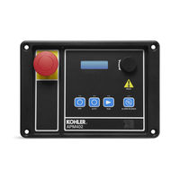
Kohler Decision-Maker 3000 Operation (172 pages)
For Industrial Generator Set 10-1000 kW
Brand:
Kohler
| Category:
Controller
| Size: 5 MB
Table of Contents
Table of Contents
3
Safety Precautions and Instructions
7
Introduction
13
Service Assistance
15
Specifications and Features
17
Introduction
17
Controller Features
17
Switches and Controls
18
Annunciator Lamps
19
Digital Display
21
Controller Fault Diagnostics
28
Digital Display Circuit Board and Connections
30
Main Logic Circuit Board
31
Terminal Jumper
32
Communication Ports
33
Fuses
33
Controller Logic Specifications
34
Status Event and Fault Specifications
35
Voltage Regulator and Calibration Specifications
41
Voltage Regulator Adjustments
41
Operation
43
Prestart Checklist
43
Exercising Generator Set
44
Operations in Cold Weather Climates
44
Controller Operation
44
Starting
45
Stopping (User Stopping and Fault Shutdown)
46
Emergency Stop Switch Resetting
46
System Status Lamps
46
System Fault Warning Lamp with Digital Displays
46
System Fault Shutdown Lamp with Digital Displays
49
Status and Notice Digital Displays
52
Controller Resetting (Following System Shutdown or Warning)
54
Powering up the Engine Control Module (ECM)
55
Menu Displays
57
Monitoring and Programming Setup
59
PC Communications
59
Modbus® Communications
60
Reviewing Menu Displays
60
Error Messages
62
Overview
63
Engine Metering
64
Generator Metering (and Calibration)
64
Genset Information
67
Genset Run Time
67
Genset System
67
Genset Calibration
68
Voltage Regulator
70
Digital Inputs
71
Digital Outputs
72
Analog Inputs
75
Battery Charger 1 and 2
76
Event Log
77
Volt Select
77
Scheduled Maintenance
79
Alternator Service
79
Engine Service
79
Service Schedule
80
Alternator Bearing Service
82
Kw Models
82
300-1000 Kw Models with 4M/5M/7M Single-Bearing Alternator
82
Diesel Fuel Systems
82
Bleeding Air from Fuel System
82
Gaseous Fuel Systems
83
Gaseous Fuel System Concept (Single Fuel)
84
LPG Liquid Withdrawal Fuel System Concept
84
Natural Gas and LPG Conversion
85
Fuel System Changeover Kits (Dual Fuel)
85
Fuel Conversion Connections
86
Crankcase Ventilation (CCV) Heater Kit GM78171-KP1
101
Air Cleaner Restrictor Indicator (if Equipped)
101
Cooling System
102
Coolant Level Check
102
Cooling System Component Inspection
102
Procedure to Drain Cooling System
103
Procedure to Flush and Clean Cooling System
103
Procedure to Refill Cooling System
103
Battery
104
Clean the Battery
106
Electrolyte Level Inspection
106
Specific Gravity Check
107
Charge Battery
108
Storage Procedure
108
Lubrication System
109
Cooling System
109
Diesel Fuel System Storage
109
Gaseous Fuel System Storage
109
Exterior
110
Alternator
110
Battery
111
General Troubleshooting
113
General Troubleshooting Chart
114
Controller Display and Voltage Regulation Troubleshooting Chart
119
Voltage Reconnection
121
Introduction
121
Voltage Reconnection Procedure
122
Voltage Reconnection Procedure
123
Accessories
129
Accessories and Connections
129
Battery Chargers
130
Battery Charger Kit with Alarm Option
130
Common Fault/Failure (32A) Relay
132
Four-Input/Fifteen-Output Module
133
Gas Fuel Valve Kit
137
Two-Input/Five-Output Module
138
Manual Key Switch
139
Low Fuel (Level/Pressure) Switch
140
Manual Speed Adjust (Engine RPM Menu)
141
Prime Power Switch Kit
141
Remote Emergency Stop Kit
142
Lockable Emergency Stop Switch
142
Remote Reset Feature
144
Remote Serial Annunciator
145
Run Relay Kit
147
Shunt-Trip Line Circuit Breaker
148
Accessory Connections
149
Appendix A. Abbreviations
155
Appendix B. Programmer-Defined Settings
159
Appendix C. Voltage Regulator Definitions and Adjustments
166
Appendix D. Alternator Protection
169
Appendix E. Controller Displays from the Engine ECM
170
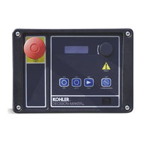
Kohler Decision-Maker 3000 Operation (100 pages)
Industrial Generator Sets
Brand:
Kohler
| Category:
Controller
| Size: 3 MB
Table of Contents
Product Identification Information
2
Table of Contents
3
Safety Precautions and Instructions
5
Introduction
9
Abbreviations
9
List of Related Materials
9
Sitetecht Software
9
Service Assistance
10
Section 1 Specifications and Features
11
Introduction
11
Controller Features
11
Switches and Controls
12
Annunciator Lamps
12
Digital Display
14
Controller Fault Diagnostics
18
Digital Display Circuit Board and Connections
20
Main Logic Circuit Board
20
Terminal Jumper
21
Communication Ports
21
Fuses
21
Controller Logic Specifications
22
Status Event and Fault Specifications
22
Voltage Regulator and Calibration Specifications
26
Voltage Regulator Adjustments
26
Section 2 Operation
27
Prestart Checklist
27
Exercising Generator Set
27
Controller Operation
27
Starting
28
Stopping (User Stopping and Fault Shutdown)
29
Emergency Stop Switch Resetting
29
System Status Lamps
29
System Fault Warning Lamp with Digital Displays
30
System Fault Shutdown Lamp with Digital Displays
32
Status and Notice Digital Displays
34
Controller Resetting (Following System Shutdown or Warning)
36
Menu Displays
36
Monitoring and Programming Setup
38
PC Communications
38
Modbusr Communications
38
Reviewing Menu Displays
39
Error Messages
39
Overview
40
Engine Metering
40
Generator Metering (and Calibration)
41
Genset Information
42
Genset Run Time
42
Genset System
42
Genset Calibration
43
Voltage Regulator
44
Digital Inputs
45
Digital Outputs
46
Analog Inputs
47
Event Log
48
Volt Select
48
Section 3 Scheduled Maintenance
49
Alternator Service
49
Engine Service
49
Service Schedule
50
Alternator Bearing Service
52
300 Kw Models
52
1000 Kw Models with 4M/5M/7M Single-Bearing Alternator
52
Diesel Fuel Systems
52
Bleeding Air from Fuel System
52
Gas Fuel Systems
52
Gas Fuel System Concept (Single Fuel)
52
LPG Liquid Withdrawal Fuel System Concept
53
Natural Gas and LPG Conversion
53
Fuel System Changeover Kits (Dual Fuel)
53
Crankcase Ventilation (CCV) Heater Kit GM78171-KP1
55
Cooling System
55
Coolant Level Check
55
Cooling System Component Inspection
55
Procedure to Drain Cooling System
56
Procedure to Flush and Clean Cooling System
56
Procedure to Refill Cooling System
56
Battery
57
Clean Battery
58
Electrolyte Level Inspection
58
Specific Gravity Check
58
Charge Battery
59
Storage Procedure
59
Lubricating System
59
Cooling System
59
Fuel System
59
Internal Engine Components (Gas-Fueled Engines)
60
Exterior
60
Battery
60
Section 4 General Troubleshooting
61
General Troubleshooting Chart
62
Controller Display and Voltage Regulation Troubleshooting Chart
65
Section 5 Voltage Reconnection
67
Introduction
67
Voltage Reconnection Procedure (Software Version 2.8 or Higher)
68
Voltage Reconnection Procedure (Software Version before 2.8)
68
Section 6 Accessories
73
Accessories and Connections
73
Common Fault/Failure (32A) Relay Kit
73
Float/Equalize Battery Charger Kit with Alarm Option
74
Gas Fuel Valve Kit
74
Input/Output (I/O) Module Board
75
Low Fuel (Level/Pressure) Switch
76
Prime Power Switch Kit
76
Remote Emergency Stop Kit
77
Remote Reset Feature
77
Remote Serial Annunciator
78
Run Relay Kit
80
Shunt-Trip Line Circuit Breaker
80
Accessory Connections
81
Appendix A Abbreviations
85
Appendix B Programmer-Defined Settings
87
Appendix C Voltage Regulator Definitions and Adjustments
91
Appendix D Alternator Protection
95
Advertisement
Advertisement
Related Products
Kohler Decision-Makerr 6000
Kohler Decision-Maker MPAC 750
Kohler Decision-Maker 3+
Kohler Decision-Maker 550
Kohler Decision-Maker 6000
Kohler DEVONSHIRE Series
Kohler Mira Showers Decor 8.5 kW
Kohler Mira Showers Decor 9.5 kW
Kohler Mira Showers Decor 10.8 kW
Kohler DC2
Kohler Categories
Plumbing Product
Bathroom Fixtures
Toilets
Bathtubs
Engine
More Kohler Manuals
Login
Sign In
OR
Sign in with Facebook
Sign in with Google
Upload manual
Upload from disk
Upload from URL