
Related Manuals for Kohler APM402


Summary of Contents for Kohler APM402
- Page 1 Operation Industrial Generator Set Models: 10-1000 kW Controller: ® APM402/Decision-Maker 3000 TP 6694 9/20m...
- Page 2 WARNING: This product can expose you to chemicals, including carbon monoxide and benzene, which are known to the State of California to cause cancer and birth defects or other reproductive harm. For more information go to www.P65warnings.ca.gov WARNING: Breathing diesel engine exhaust exposes you to chemicals known to the State of California to cause cancer and birth defects or other reproductive harm.
-
Page 3: Table Of Contents
Table of Contents Safety Precautions and Instructions ............................7 Introduction ....................................13 Service Assistance................................... 15 Section 1. Specifications and Features ......................... 17 Introduction ................................17 Controller Features..............................17 1.2.1 Switches and Controls ..........................18 1.2.2 Annunciator Lamps ..........................19 1.2.3 Digital Display ............................ - Page 4 2.7.11 Digital Outputs ............................72 2.7.12 Analog Inputs ............................75 2.7.13 Battery Charger 1 and 2 ........................... 76 2.7.14 Event Log ..............................77 2.7.15 Volt Select ..............................77 Section 3. Scheduled Maintenance ........................79 Alternator Service ..............................79 Engine Service ............................... 79 Service Schedule ..............................
- Page 5 Section 6. Accessories ............................129 Accessories and Connections ..........................129 6.1.1 Battery Chargers ............................ 130 6.1.2 Battery Charger Kit with Alarm Option ....................130 6.1.3 Common Fault/Failure (32A) Relay ......................132 6.1.4 Four-Input/Fifteen-Output Module ......................133 6.1.5 Gas Fuel Valve Kit ..........................137 6.1.6 Two-Input/Five-Output Module .......................
- Page 6 TP-6694 9/20...
-
Page 7: Safety Precautions And Instructions
Safety Precautions and Instructions IMPORTANT SAFETY INSTRUCTIONS. Electromechanical equipment, including generator sets, transfer switches, switchgear, and accessories, can cause bodily harm and pose life-threatening danger when improperly installed, operated, or maintained. To prevent accidents be aware of potential dangers and act safely. Read and follow all safety precautions and instructions. SAVE THESE INSTRUCTIONS. - Page 8 WARNING Explosion. Can cause severe injury or death. Relays in the battery charger cause arcs or sparks. Locate the battery in a well‐ventilated area. Isolate the battery charger from explosive fumes. Battery electrolyte is a diluted sulfuric acid. Battery acid can cause severe injury or death. Battery acid can cause blindness and burn skin.
- Page 9 Exhaust System WARNING Carbon monoxide. Can cause severe nausea, fainting, or death. The exhaust system must be leakproof and routinely inspected. Generator set operation. Carbon monoxide can cause severe nausea, fainting, or death. Carbon monoxide is an odorless, colorless, tasteless, nonirritating gas that can cause death if inhaled for even a short time. Avoid breathing exhaust fumes when working on or near the generator set.
- Page 10 Gas fuel leaks. Explosive fuel vapors can cause severe injury or death. Fuel leakage can cause an explosion. Check the LPG vapor or natural gas fuel system for leakage by using a soap and water solution with the fuel system test pressurized to 6– 8 ounces per square inch (10–14 inches water column).
- Page 11 Installing the battery charger. Hazardous voltage will cause severe injury or death. An ungrounded battery charger may cause electrical shock. Connect the battery charger enclosure to the ground of a permanent wiring system. As an alternative, install an equipment grounding conductor with circuit conductors and connect it to the equipment grounding terminal or the lead on the battery charger.
- Page 12 WARNING Hot engine and exhaust system. Can cause severe injury or death. Do not work on the generator set until it cools. Servicing the alternator. Hot parts can cause severe injury or death. Avoid touching the alternator field or exciter armature. When shorted, the alternator field and exciter armature become hot enough to cause severe burns.
-
Page 13: Introduction
Wiring diagram manuals are available separately. Refer to the engine operation manual for generator set engine scheduled maintenance information. Information in this publication represents data available at the time of print. Kohler Co. reserves the right to change this publication and the products represented without notice and without any obligation or liability whatsoever. - Page 14 List of Related Materials Separate literature contains communication and software information not provided in this manual. Figure 1 lists the available literature part numbers. Literature Description Literature Part No. APM402 Controller Spec Sheet G6-161 ® Decision-Maker 3000 Controller Spec Sheet...
-
Page 15: Service Assistance
(86) 10 6518 7950 Visit the Kohler Co. website at KOHLERPower.com. (86) 10 6518 7951 Look at the labels and decals on your Kohler product (86) 10 6518 7952 or review the appropriate literature or documents Fax: (86) 10 6518 7955 included with the product. - Page 16 TP-6694 9/20...
-
Page 17: Specifications And Features
Section 1. Specifications and Features 1.1 Introduction The spec sheets for each generator set provide model-specific generator and engine information. The controller spec sheet provides specifications for this controller. Refer to the respective spec sheet for data not supplied in this manual. Refer to the generator set service manual, installation manual, engine operation manual, and engine service manual for additional specifications. -
Page 18: Switches And Controls
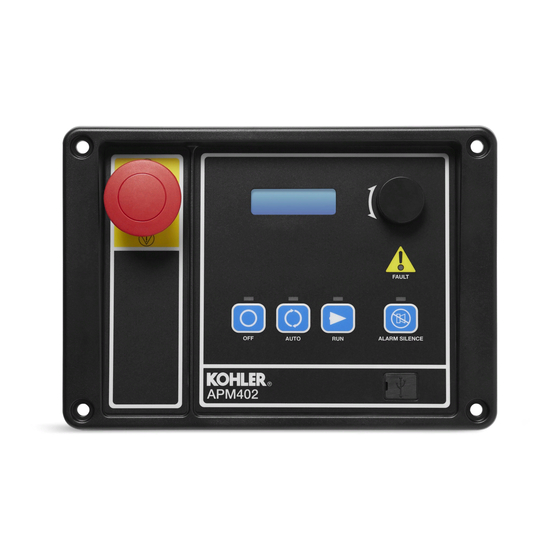
1.2.1 Switches and Controls Note: US/Metric Display is selectable in the Generator Set System Menu. See the section titled: Digital Display-Generator Set System Menu. Alarm Horn. The alarm horn alerts the operator or other attendants that a shutdown or warning condition exists. Alarm (Horn) Silence. -
Page 19: Annunciator Lamps
1.2.2 Annunciator Lamps The controller has a single annunciator fault lamp providing visual generator set status. In addition, each button has a corresponding lamp. See Figure 3. Lamp/Button Lamp color Alarm (Fault) Lamp Yellow (Warning) or Red (Shutdown) Off/Reset Button Auto Button Green (System Ready) Run Button... - Page 20 High fuel level (diesel-powered models only) * Input/output communication loss Low battery voltage Low coolant temperature Low cranking voltage Low engine oil level * Low fuel (level for diesel-powered models) * Low fuel (pressure for gas-powered models) * ...
-
Page 21: Digital Display
Note: The APM402 controller takes about 5-10 seconds to power on. The generator set must be running for some displays to indicate values. If the generator set is not running some values will display zero or N/A (not available). - Page 22 CHG1 and CHG2 display battery charger voltage and current (amps) if one or two CAN-enabled 10 Amp battery chargers (GM87448 only) have been connected. Shows N/A if charger GM87448 was connected and then removed. (DEC3000 version 4.11 or higher, and APM402). Engine Run Time displays the total run time hours.
- Page 23 Oil Pressure displays the engine oil pressure. This value also shows in the Overview Menu. Coolant Temperature displays the engine coolant temperature. This value also shows in the Overview Menu. Fuel Level % displays the fuel tank level for diesel-powered models if so equipped. This value also shows in the Overview Menu.
- Page 24 3000 controller firmware versions before 3.0.25. On Decision-Maker 3000 controllers with later firmware versions, or on APM402 controllers, go to Generator Metering Menu—Reset Calibration. The calibration values are reviewable at all times and provide the calibration of the voltage and current sensing logic. Changing the system voltage or replacing the circuit board requires a calibration adjustment.
- Page 25 ® Decision-Maker 3000 Controller firmware 3.0.25 and higher, or APM402 Controller: The voltage regulator value is reviewable at all times and provides the ability to fine adjust voltage. Changing the system voltage or replacing the circuit board typically requires a voltage adjustment.
- Page 26 Digital Inputs Menu This menu allows the user to review the settings. There are up to three digital inputs that are programmer selectable if not reserved by factory options. The displays for digital inputs appear as shown below with Values true or false. Items shown in the digital display as True are active.
- Page 27 Event Log Menu This menu allows the user to review up to 1000 entries of system events including shutdown faults, warning faults, and status events. See the section titled: Controller Fault Diagnostics for a list of the items that appear on the Event Log. Volt Select Menu Note: The generator set must be stopped before changing the voltage selection.
-
Page 28: Controller Fault Diagnostics
1.2.4 Controller Fault Diagnostics This table provides descriptions of the system events and their types—warning, shutdown, status, and notice. Warnings show yellow fault lamp and signal an impending problem. Shutdowns show red fault lamp and stop the generator set. Status is an event that is not an alert but is part of the event history. Notice is an alert that is NOT part of the event history. System events are available as a Relay Output as shown. - Page 29 Warning Shutdown Status/ Relay Description Display Message Function Function Notice Output General Functions Alarm horn silenced (Alarm Silence LED only) Alarm silence, auto only (NFPA 110) or always AlrmSilence: Auto Only or AlrmSilence: Always Aux. inputs 0- 5 VDC, 1 analog Aux Input Warning (2 additional inputs available with I/O module option) Aux.
-
Page 30: Digital Display Circuit Board And Connections
1.2.5 Digital Display Circuit Board and Connections The digital display circuit board provides: The backlit LCD (liquid crystal display) for monitoring the generator set functions and output values Master control switches with status lights Fault lamp Pushbutton/rotary selector dial to navigate the generator set displays ... -
Page 31: Main Logic Circuit Board
1.2.6 Main Logic Circuit Board The main logic circuit board provides the terminal strips and connection sockets to connect the controller to the engine/generator, input/output connections, optional I/O module kit, and circuit protection fuses. See Figure 5 and Figure 6 for the circuit board connections. -
Page 32: Terminal Jumper
(4) push-on terminal connectors TB2 4-position terminal block P21 6-pin connector (for RS-485 communications) TB3 6-position terminal block P23 8-pin connector (RJ45) P30 jumper (Wound Field or Fast Response) P1 24-pin connector TB1 6-position terminal block GM102396 Figure 6 Main Circuit Board Connectors ®... -
Page 33: Communication Ports
1.2.8 Communication Ports ® The main logic circuit board contains a single mini USB communication port for PC connections, see Figure 7. For Modbus communication using RS-485, see the figure titled: Main Circuit Board Connectors (P21). Refer to the List of Related Materials in the Introduction for corresponding SiteTech™... -
Page 34: Controller Logic Specifications
V7/V8/V9 fuses, 1.5 Amp. (qty. 3) GM69407 Figure 8 AC Circuit Fuses in Control Box F2 1 Amp. auto-resettable F3 12 Amp. non-replaceable F1 1 Amp. auto-resettable GM6435-C Figure 9 Controller DC Fuses 1.3 Controller Logic Specifications The controller logic specifications section is an overview of the various features and functions of the controller. Certain features function only when optional accessories are connected. -
Page 35: Status Event And Fault Specifications
1.3.1 Status Event and Fault Specifications The Factory-Defined Settings List contains all status events and faults with ranges and time delays including items that do not have user adjustments. Note: The engine ECM may limit the crank cycle even if the controller is set to a longer time period. Factory-Defined Settings List GenSet Fault... - Page 36 GenSet Fault Write Mode Time Default Controller Lamp Access Always Delay Time Display Alarm Warning Display Running Range Default Range Delay Description Message Horn Setting Selection (sec.) (sec.) Shutdown SiteTech Stopped Low cranking voltage Lo Crank Vlt Fixed Fixed Warning Low engine oil level * Oil Level Low Warning...
- Page 37 GenSet Fault Write Mode Time Default Controller Lamp Access Always Delay Time Display Alarm Warning Display Running Range Default Range Delay Description Message Horn Shutdown SiteTech Stopped Setting Selection (sec.) (sec.) Chicago Code Chicago code active * Active Common Fault Common fault Shutdwn Common...
- Page 38 GenSet Fault Write Mode Time Default Controller Lamp Access Always Delay Time Display Alarm Warning Display Running Range Default Range Delay Description Message Horn Setting Selection (sec.) (sec.) Shutdown SiteTech Stopped Alternator protection Alt Protect Shutdwn Ground fault input * Ground Fault Warning kW overload...
- Page 39 GenSet Fault Write Mode Time Default Controller Lamp Access Always Delay Time Display Alarm Warning Display Running Range Default Range Delay Description Message Horn Setting Selection (sec.) (sec.) Shutdown SiteTech Stopped Charger Depleted Battery 4–12 Voltage Target (12 V) (12 V) 18–24 (24 V) (24 V)
- Page 40 GenSet Fault Write Mode Time Default Controller Lamp Access Delay Time Always Display Alarm Warning Display Running Range Default Range Delay Description Message Horn Shutdown SiteTech Stopped Setting Selection (sec.) (sec.) Charger Voltage Absorption (V) 13–15 14.25 (12 V)** (12 V) 26–30 28.5 (24 V)**...
-
Page 41: Voltage Regulator And Calibration Specifications
1.3.2 Voltage Regulator and Calibration Specifications The controller has a voltage regulation function that is internal to the processor. This means that no external voltage regulator is necessary. The voltage regulation of the controller uses root mean square (rms) sensing for fast response to changes in indicated and regulated voltages resulting in excellent regulation accuracy. - Page 42 TP-6694 9/20...
-
Page 43: Operation
Section 2. Operation 2.1 Prestart Checklist To ensure continued satisfactory operation, perform the following checks or inspections before or at each startup, as designated, and at the intervals specified in the service schedule. In addition, some checks require verification after the unit starts. DANGER Hazardous voltage. -
Page 44: Exercising Generator Set
2.2 Exercising Generator Set DANGER Hazardous voltage. Moving parts. Will cause severe injury or death. Operate the generator set only when all guards and electrical enclosures are in place. Operate the generator set under load once each week for one hour. Perform the exercise in the presence of an operator when the generator set does not have an automatic transfer switch with an exercise option. -
Page 45: Starting
2.4.1 Starting Local Starting Press the master control RUN button to start the generator set at the controller. Note: The alarm horn sounds and the Not-In-Auto Warning display appears whenever the generator set master control button is not in the AUTO mode. Button Generator Alarm... -
Page 46: Stopping (User Stopping And Fault Shutdown)
CONTROLLER OFF position. When the generator set is the prime power mode, all controller functions including the digital display, LEDs, alarm horn, and communications are inoperative. 2.4.2 Stopping (User Stopping and Fault Shutdown) Normal Stopping Run the generator set without load for 5 minutes to ensure adequate engine cooldown. The controller has a programmable cooldown timer that functions only when the master control button is in the AUTO mode. - Page 47 empty. This fault requires an optional low fuel level switch for the lamp to function. The local display shows Fuel Level Low Warning. See the section titled: Controller Resetting procedure, for instructions on resetting a system warning. When the system warning lamp is on and no message displays, rotate the selector dial to view messages. When the system warning continues, it may lead to a fault and cause a system shutdown.
- Page 48 Fuel Tank Leak (diesel-powered models only). The fault lamp illuminates yellow and the alarm horn sounds when the fuel tank signals a leak of the inner tank. This fault requires an optional fuel tank leak switch for the lamp to function. The local display shows Fuel Leak Warning.
-
Page 49: System Fault Shutdown Lamp With Digital Displays
Speed Sensor Fault. The fault lamp illuminates yellow and the alarm horn sounds when the speed signal is absent for one second while the generator set runs. The local display shows Spd Sens Flt Warning. 2.4.6 System Fault Shutdown Lamp with Digital Displays The system FAULT lamp glows red, the alarm horn sounds, and the unit shuts down to indicate a fault shutdown under the following conditions. - Page 50 Engine Under Speed. The fault lamp illuminates red, the alarm horn sounds, and the unit shuts down immediately when the governed frequency on 50 and 60 Hz models drops below the under speed setting. The local display shows Eng Speed Low Shutdwn.
- Page 51 Overcrank. The fault lamp illuminates red, the alarm horn sounds, and cranking stops when the unit does not start within the defined cranking period. The local display shows Over Crank Shutdwn. See the section titled: Auto Starting, and the section titled: Status Event and Fault Specifications for cyclic crank specifications.
-
Page 52: Status And Notice Digital Displays
Chicago Code Active. This notice message indicates that the controller is locked in AUTO mode. This feature requires a digital input assigned to Chicago Code Active. A Kohler authorized distributor or dealer can use SiteTech™ software to assign a digital input to Chicago Code Active. When the digital input is active, the local display shows Chicago Code Active. - Page 53 Volts L3- N: x.x V Current L1: x.x A Current L2: x.x A Current L3: x.x A The user can individually calibrate the values above or reset all of them. The local display Reset all calib? No or Yes. Select No to make no changes and exit GenSet Calibration.
-
Page 54: Controller Resetting (Following System Shutdown Or Warning)
2.4.8 Controller Resetting (Following System Shutdown or Warning) Use the following procedure to restart the generator set after a system shutdown or to clear a warning lamp condition. This procedure includes the resetting of the optional remote annunciator. Refer to the section titled: Emergency Stop Switch Reset Procedure, to reset the generator set after an emergency stop. Disconnect the generator set load using the line circuit breaker or automatic transfer switch. -
Page 55: Powering Up The Engine Control Module (Ecm)
® The Decision-Maker 3000 controller (with firmware version 3.10 and higher) and the APM402 controller have the capability to power up the engine ECM. On generator sets with John Deere engines, the engine ECM power-up feature allows service technicians to access fault codes and other troubleshooting data using their John Deere Diagnostic tools without the need to start the generator set. - Page 56 Powered Figure 20 ECM Powered Display After several seconds, the display will change to provide the option to power down the controller. See Figure 21. ECM powered Push to Stop Figure 21 ECM Power Down Display If desired, press the selector dial to power down the engine ECM. Rotate the selector dial to navigate to any of the available menus.
-
Page 57: Menu Displays
Menu Summary List (Legend: ● First level submenu, ○ second level submenu) Overview Menu (DEC3000 Overview Menu (DEC3000 Generator Metering Menu GenSet System Menu before version 4.11) version 4.11 and APM402) Available as scrolling or fixed Available as scrolling or fixed Total Power kVA System Frequency ... - Page 58 Voltage Regulator Menu 120/240 V 1 Ph DIn B2 (with I/O Board) (DEC3000 Version 3.0.25 120/208 V 3 Ph or higher, and APM402) 139/240 V 3 Ph Digital Outputs Menu Voltage Regulator Voltage Battery Charger 1 Menu 277/480 V 3 Ph ...
-
Page 59: Monitoring And Programming Setup
2.6 Monitoring and Programming Setup The user programmer can access the controller data with the controller digital display or a personal computer (PC) with optional SiteTech™ software to monitor and/or program. Access the controller system with a PC using a USB cable with a mini USB plug. -
Page 60: Modbus® Communications
2.6.2 Modbus® Communications ® ® The controller communicates using Modbus as a slave connection with the Modbus master initiating the communication. The ® controller seeks the system and alternator parameters and diagnostic information then responds back to the Modbus master. In addition, the controller accepts information to alter controller parameters including generator set starting and stopping. - Page 61 Controller Controller SiteTech Menu Name Viewable Adjustable Adjustable Overview Engine Metering Generator Metering GenSet Information GenSet Run Time GenSet System Voltage Regulation Digital Inputs Digital Outputs Analog Inputs Event Log Volt Select * Requires initial activation using SiteTech™ Figure 27 Displays for Viewing and Adjusting (DEC3000 Firmware Version 3.0.25 to 4.8.4) Controller Controller...
-
Page 62: Error Messages
2.7.1 Error Messages Certain entries or attempted entries may cause the controller to display an error message. Some of the error messages shown here are also shown as part of the section titled: System Fault Warning Lamp with Digital Displays and the section titled: System Fault Shutdown Lamp with Digital Displays. -
Page 63: Overview
2.7.2 Overview Displays basic and commonly sought after information about the generator set. This information scrolls automatically after about 5 minutes of no user input (pushbutton/rotary selector dial or button activity). To change from auto scrolling to fixed display, press the rotary dial and the main menu will appear. Press the rotary dial again to select the first menu item Overview. -
Page 64: Engine Metering
Overview (Fixed Display) Overview - - > ### V ##.# Hz ##.# hr ### A #### kW English Display ###_F ###% Measurements - > ### PSI ##.# V Metric Display ###_ C ##.# % Measurements - > #.# MPa ##.# V CHG1: ##.#V With 10 Amp Charger ##.# A... - Page 65 To enable calibration, start the generator set and select the Volts L1-L2 display. Then push and hold the pushbutton/rotary selector dial until the Calibration Enabled popup appears. Calibration of each display is now available. The display will show the following values for three-phase generator sets. Single-phase generator sets will only display items marked (*). ...
- Page 66 Generator Metering Generating - - > Total Power: Metering # VA Total Power: Rated Power: Select this Display to Enable or Disable Volts L1- L2: Calibration - - > #.# V Volts L2- L3: #.# V Volts L3- L1: #.# V Volts L1- N: #.# A Volts L2- N:...
-
Page 67: Genset Information
2.7.5 GenSet Information Displays generator set and controller information. Displayed data is factory entered. GenSet Information GenSet - - > Genset M/N: Information GenSet S/N: Cntrllr S/N: 2.7.6 GenSet Run Time Displays the generator set’s operating record including total run time loaded and unloaded, number of starts, and total energy kW hours GenSet Run Time GenSet - - >... -
Page 68: Genset Calibration
GenSet System GenSet - - > System System Freq: ##.# Hz SystemPhase: ##### System Volt: ###.# V Pwr Rating: ##.# kW Amp Rating: ##.# A Power Type: ##### Battery v: ## V Meas System User Selectable - > English or Metric Contrast User Selectable - >... - Page 69 GenSet Calibration GenSet - - > Enter Calib? GenSet - - > Calibration Calibration Enter Calib? User Selectable - > Volts L1- L2: #.# V Volts L2- L3: #.# V Volts L3- L1: #.# V Volts L1- N: #.# A Volts L2- N: #.# A Volts L3- N:...
-
Page 70: Voltage Regulator
® Decision-Maker 3000 Controllers with Firmware Version 3.0.25 or Higher, or APM402 Controllers. Displays the voltage regulator adjustment value. All other voltage regulator adjustments are changed using SiteTech™ software. The voltage regulator value is reviewable at all times and provides the ability to fine adjust voltage. Changing the system voltage or replacing the circuit board typically requires a voltage adjustment. -
Page 71: Digital Inputs
2.7.10 Digital Inputs Displays the selected programming user-defined digital notice, warning, and shutdown inputs. These inputs provide a multitude of choices for configuring customized auxiliary inputs. See Figure 29 for a list of digital input choices. For descriptions of the inputs listed refer to the following sections: ... -
Page 72: Digital Outputs
Critical Analog and Digital High High High Inputs Notice Warning Warning Warning Warning Shutdown Shutdown Shutdown Auxiliary Input Battery Charger Fault Chicago Code Active Enclosure Temperature: High Shutdown (Din A3) Engine Fuel Level Fuel Tank Leak Ground Fault Low Engine Oil Level Low Fuel Pressure Figure 29 Analog and Digital Inputs... - Page 73 Digital Outputs Digital - - > DOut A1 Outputs ##### DOut A1 Value: True or False DOut B1 ##### DOut B1 Value: True or False DOut B2 ##### DOut B2 Value: True or False DOut B3 ##### DOut B3 Value: True or False DOut B4 ##### DOut B4...
- Page 74 Critical No Signal High High High Shut- Shut- Shut- Digital Outputs Notice Warning Warning Warning Warning Shutdown down down down AC Sensing Lost Alternator Protection Auxiliary Input Battery Charger Fault Battery Voltage Chicago Code Active Common Fault Common Warning Cranking Voltage ECM Comm Loss Emergency Stop Engine Coolant Level...
-
Page 75: Analog Inputs
2.7.12 Analog Inputs Displays the selected programming user-defined analog notice, warning, and shutdown inputs. These inputs provide a multitude of choices for configuring customized auxiliary inputs. See the figure titled: Analog and Digital Inputs for a list of analog input choices. -
Page 76: Battery Charger 1 And 2
Battery charger menus are available on Decision-Maker 3000 Controllers with controller firmware version 4.8.4 and higher, and on APM402 controllers. Battery Charger 1 and 2 menus provide battery charger information and metering. Use this menu to view the charger output metering and charger states. -
Page 77: Event Log
2.7.14 Event Log Displays up to 1000 stored status, warning, and shutdown events. After the first 1000 events, each additional new event replaces the oldest event. See the section titled: Controller Fault Diagnostics for a list of possible events. Event Log Event Log - - >... - Page 78 TP-6694 9/20...
-
Page 79: Scheduled Maintenance
Note: Have maintenance work, including battery service, performed by appropriately skilled and suitably trained maintenance personnel familiar with generator set operation and service. Kohler recommends the use of Kohler Genuine oil and filters for maintenance and service. TP-6694 9/20... -
Page 80: Service Schedule
3.3 Service Schedule Action System—Component Visually Inspect Check Change Clean Test Interval Fuel System Day tank level Weekly Flexible lines and connections Weekly Fuel level switch Weekly Main tank supply level Weekly Solenoid valve operation Weekly Transfer pump operation Weekly ●... - Page 81 Action System—Component Visually Inspect Check Change Clean Test Interval AC Electrical System Controller lamp test Weekly General Inspection Weekly Circuit breakers, fuses† Monthly Wire abrasions where subject to motion Quarterly Safety and alarm operation Six Months Tighten control and power wiring Yearly connections Transfer switch main contacts†...
-
Page 82: Alternator Bearing Service
3.4 Alternator Bearing Service Have an authorized service distributor/dealer perform service. 3.4.1 20-300 kW Models Replace the end bracket bearing every 10,000 hours of operation. Service the bearing more frequently if the annual inspection indicates excessive rotor end play or bearing damage. The sealed end bracket bearing requires no additional lubrication. 3.4.2 300-1000 kW Models with 4M/5M/7M Single-Bearing Alternator The alternator bearing requires lubrication at intervals specified in the alternator operation and maintenance manual. -
Page 83: Gaseous Fuel Systems
Close the fuel valves on each side of the fuel prime pump. 3.6 Gaseous Fuel Systems Gaseous fuel systems apply to KG_ (Kohler Powered), (REZG_/RZG_/ERES_ (GM/PSI Powered), REZX_/RZX_ (Doosan Powered) generator set models. This section describes natural gas and liquified petroleum gas (LPG) fuel systems that are not covered in the engine operation manual or engine service manual. -
Page 84: Gaseous Fuel System Concept (Single Fuel)
3.6.1 Gaseous Fuel System Concept (Single Fuel) The gaseous fuel system uses a fuel solenoid valve to control the fuel flow to the electronic-controlled pressure regulator (EPR) or direct acting electronic pressure regulator (DEPR). The generator set-mounted EPR or DEPR reduces the fuel pressure as fuel passes to the fuel mixer. -
Page 85: Natural Gas And Lpg Conversion
3.6.3 Natural Gas and LPG Conversion Most gaseous-fueled models can be converted to operate on either natural gas or LPG fuel. The engine ECM has fuel tables and spark advance curves programmed for both natural gas and LPG. To change the fuel type, change the electrical connections between the fuel system and the engine ECM as shown in the following instructions and connection diagrams. -
Page 86: Fuel Conversion Connections
3.6.5 Fuel Conversion Connections To change the fuel type, change the wiring harness connections. The engine ECM has fuel tables and spark advance curves programmed for both natural gas and LPG. Use the following fuel connection tables and wiring diagrams to determine the applicable connections for your generator set model. - Page 87 Natural Gas LPG Vapor To ECM To ECM controller controller LPG Liquid To ECM controller Auto Changeover Natural Gas and LPG Vapor To ECM controller ADV-7600B-F Figure 34 Gaseous Fuel Connections Wiring Diagram, Typical Models with PSI or GM Engines TP-6694 9/20...
- Page 88 For KG40, KG45, KG50, KG60 (Koher Engine KG6208), use the following: See Figure 35 and Figure 36. Natural Gas Operation Disconnect 78/78a and 70G/70R from the fuel valve. Disconnect 49 and N17. Connect 77/77a and 70H/70T to the fuel valve. LPG Vapor Operation ...
- Page 89 Natural Gas LPG Vapor To ECM To ECM controller controller Auto Changeover Natural Gas and LPG Vapor To ECM controller ADV-9007D-C Figure 36 Gaseous Fuel Connections Wiring Diagram, KG40–KG60 (KG6208) TP-6694 9/20...
- Page 90 For KG80–KG125, KG80R–KG125R (Kohler Engines KG6208TSD and KG6208THD), use the following: See Figure 37 and Figure 38. Natural Gas Operation Disconnect the black fuel connector (J7). Disconnect 49 and N17. Connect the white fuel connector (J8). ...
- Page 91 Natural Gas LPG Vapor To ECM To ECM controller controller Auto Changeover Natural Gas and LPG Vapor To ECM controller ADV-9052D-D Figure 38 Gaseous Fuel Connections Wiring Diagram, KG80–KG125/KG80R–KG125R TP-6694 9/20...
- Page 92 KG80–KG125, KG80R–KG125R Dual Fuel Operation The dual fuel system for the KG80–KG125 and KG80R–KG125R includes an LPG indicator light and a reset switch. This LPG indicator light turns on when the NG fuel valve closes and the LP fuel valve opens, indicating that the fuel source has switched. The reset switch resets the fuel source to natural gas.
- Page 93 For KG150, KG180, and KG200 (Kohler Engines KG10V08T-6CGS and KG10V08T-6DGS), use the following: To change the fuel type, change the wiring harness connections. The engine ECM has fuel tables and spark advance curves programmed for both natural gas and LPG. Use the following fuel connection tables and wiring diagrams to determine the applicable connections for your generator set model.
- Page 94 Natural Gas LPG Vapor To ECM and To ECM and controller controller ADV-9116 Figure 41 Gaseous Fuel Connections Wiring Diagram, Single Fuel, KG150, KG180, and KG200 TP-6694 9/20...
- Page 95 For 180-500 RZXB/REZXB/REZXC/RZXD/REZXD (PSI/ Doosan 11.1L, 14.6L, 18.3L, and 21.9L Engines), use the following: To change the fuel type, change the wiring harness connections. The engine ECM has fuel tables and spark advance curves programmed for both natural gas and LPG. Use the following fuel connection lists and wiring diagrams to determine the applicable connections for your generator set model.
- Page 96 180-500 RZXB/REZXB/REZXC/RZXD/REZXD (PSI/ Doosan 11.1L, 14.6L, 18.3L, and 21.9L Engines) Natural Gas with Additional Fuel Valve, Required for UL Approval See Figure 43. Disconnect lead N5. Disconnect lead 65. Disconnect lead 65A. Disconnect lead 73B. Connect lead 70B2 to fuel valve 1 (FV1), red/black wire.
- Page 97 Natural Gas 250 – 300 kW (14.6 L) 180 – 200 kW (11 L) ADV-7968-G ADV-7968-G 300 – 500 kW (18 – 22 L) ADV-7994-K Figure 43 Natural Gas with Additional UL Fuel Valve TP-6694 9/20...
- Page 98 180-500 RZXB/REZXB/REZXC/RZXD/REZXD (PSI/ Doosan 11.1L, 14.6L, 18.3L, and 21.9L Engines) LPG Vapor or Liquid Withdrawal with Single Fuel Valve See Figure 44. Disconnect lead 70E. Disconnect lead N6. Disconnect lead N11 (250 – 500 kW). Disconnect lead 73A (180 – 200 kW). ...
- Page 99 180-500 RZXB/REZXB/REZXC/RZXD/REZXD (PSI/ Doosan 11.1L, 14.6L, 18.3L, and 21.9L Engines) LPG Vapor or Liquid Withdrawal with Additional Fuel Valve, Required for UL Approval See Figure 45. Disconnect lead 73A (180 – 200 kW). Disconnect lead 73A and 73A1 (250 – 500 kW). ...
- Page 100 LPG Vapor and Liquid Withdrawal UL Valve 180 – 200 kW (11 L) ADV-7968-G 250 – 300 kW (14.6 L) ADV-7970-G 300 – 500 kW (18 – 22 L) ADV-7994-K Figure 45 LPG Vapor or Liquid Withdrawal with Additional UL Fuel Valve TP-6694 9/20...
-
Page 101: Crankcase Ventilation (Ccv) Heater Kit Gm78171-Kp1
3.7 Crankcase Ventilation (CCV) Heater Kit GM78171-KP1 Applies to 125/150 kW, 8.1 L GM-powered and 8.8 L PSI-powered generator set models. Consult your local generator set distributor/dealer for additional information. The crankcase ventilation (CCV) heater kit provides a controlled heating source to the crankcase ventilation system preventing freezing water buildup during cold weather. -
Page 102: Cooling System
3.9 Cooling System The cooling system maintenance information applies to radiator-cooled models which have a radiator with a pressure cap and coolant recovery tank. WARNING Hot coolant and steam. Can cause severe injury or death. Before removing the pressure cap, stop the generator set and allow it to cool. Then loosen the pressure cap to relieve pressure. -
Page 103: Procedure To Drain Cooling System
Open the air-bleed petcocks, if equipped. Close the air-bleed petcocks when coolant begins to flow from them. Note: Refer to the engine operation manual for air-bleed petcock locations. Fill the cooling system with the recommended genuine Kohler coolant/antifreeze mixture based on the engine manufacturer’s recommendation. Replace the pressure cap. -
Page 104: Battery
10. Remove the pressure cap. 11. Add coolant to bring the coolant level to just below the overflow tube opening of the filler neck. 12. Replace the pressure cap. 13. Maintain the coolant level in the coolant recovery tank (if equipped) between the high and low marks. Check the coolant level at the radiator fill on models without a coolant recovery tank. - Page 105 12-Volt 24-Volt To positive (+) terminal on starter solenoid. To ground (-) terminal on or near starter motor. EZ-273000-J Figure 48 Engine Electrical System Single Starter Motor Typical Battery Connection To positive (+) terminal on starter solenoid. To ground (-) terminal on or near starter motor.
-
Page 106: Clean The Battery
3.10.1 Clean the Battery Clean the battery and cables and tighten the battery terminals according to the service schedule recommendations. Clean the battery by wiping it with a damp cloth. Keep the electrical connections dry and tight. If corrosion exists, disconnect the cables from the battery and remove the corrosion with a wire brush. Clean the battery and cables with a solution of baking soda and water. -
Page 107: Specific Gravity Check
3.10.3 Specific Gravity Check Use a battery hydrometer to check the specific gravity of the electrolyte in each battery cell of batteries with filler caps. Holding the hydrometer vertically, read the number on the glass bulb at the top of the electrolyte level or the number adjacent to the pointer. -
Page 108: Charge Battery
3.10.4 Charge Battery Use a battery charger to maintain a fully charged battery when the generator set is used in a standby application. The engine battery-charging alternator charges the battery while the generator set is running. Refer to the battery charger operation manual for installation, operation, and service procedures. -
Page 109: Lubrication System
3.11.1 Lubrication System Prepare the engine lubricating system for storage as follows: Run the generator set for a minimum of 30 minutes to bring it to normal operating temperature. Stop the generator set. With the engine still warm, drain the oil from the crankcase. Remove and replace the oil filter. -
Page 110: Exterior
3.11.4.1 Internal Engine Components If you have access to a fogging agent or SAE 10 oil prepare the pistons and cylinders for storage as follows: While the engine is running, spray a fogging agent or SAE 10 engine oil into the air intake for about two minutes until the engine stops. -
Page 111: Battery
3.11.7 Battery WARNING Explosion. Can cause severe injury or death. Relays in the battery charger cause arcs or sparks. Locate the battery in a well‐ventilated area. Isolate the battery charger from explosive fumes. Perform battery storage after all other storage procedures. Confirm that the generator set is stopped. - Page 112 TP-6694 9/20...
-
Page 113: General Troubleshooting
Section 4. General Troubleshooting This section contains generator set troubleshooting, diagnostic, and repair information. Use the following charts to diagnose and correct common problems. First check for simple causes such as a dead engine starting battery or an open circuit breaker. The charts include a list of common problems, possible causes of the problem, recommended corrective actions, and references to detailed information or repair procedures. -
Page 114: General Troubleshooting Chart
4.1 General Troubleshooting Chart Exercise run time and/or event records inoperative Displays error message/locks up Excessive or abnormal noise High fuel consumption Low oil pressure Overheats Lacks power Stops suddenly No or low output voltage Starts hard Cranks but does not start Does not crank TP-6694... - Page 115 Exercise run time and/or event records inoperative Displays error message/locks up Excessive or abnormal noise High fuel consumption Low oil pressure Overheats Lacks power Stops suddenly No or low output voltage Starts hard Cranks but does not start Does not crank TP-6694 9/20...
- Page 116 Exercise run time and/or event records inoperative Displays error message/locks up Excessive or abnormal noise High fuel consumption Low oil pressure Overheats Lacks power Stops suddenly No or low output voltage Starts hard Cranks but does not start Does not crank TP-6694 9/20...
- Page 117 Exercise run time and/or event records inoperative Displays error message/locks up Excessive or abnormal noise High fuel consumption Low oil pressure Overheats Lacks power Stops suddenly No or low output voltage Starts hard Cranks but does not start Does not crank TP-6694 9/20...
- Page 118 Exercise run time and/or event records inoperative Displays error message/locks up Excessive or abnormal noise High fuel consumption Low oil pressure Overheats Lacks power Stops suddenly No or low output voltage Starts hard Cranks but does not start Does not crank TP-6694 9/20...
-
Page 119: Controller Display And Voltage Regulation Troubleshooting Chart
4.2 Controller Display and Voltage Regulation Troubleshooting Chart TP-6694 9/20... - Page 120 TP-6694 9/20...
-
Page 121: Voltage Reconnection
Section 5. Voltage Reconnection 5.1 Introduction Use the following voltage reconnection procedure to change the voltage of 10- and 12- lead generator sets. Frequency changes require voltage regulator and governor adjustments. Refer to the respective spec sheet to determine if frequency is fixed or field- convertible. -
Page 122: Voltage Reconnection Procedure
5.2 Voltage Reconnection Procedure Note: ® For Decision-Maker 3000 Controllers with software versions before 2.8, go to the next Section. Press the generator set master control OFF/RESET button Turn the controller pushbutton/rotary selector dial until it stops at the Volt Select menu. See Figure 53 Note: If the Volt Select menu does not appear, the controller voltage selection feature was not activated using SiteTech™... -
Page 123: Voltage Reconnection Procedure
5.3 Voltage Reconnection Procedure Note: ® This procedure applies to Decision-Maker 3000 Controllers with software versions before 2.8 only. Press the generator set master control OFF/RESET button. Disconnect the generator set engine starting battery, negative (-) lead first. Disconnect power to the battery charger (if equipped) Use Figure 54, Figure 55, Figure 56, or Figure 57 to determine the generator set voltage configuration. - Page 124 Figure 54 20- 150 kW Permanent Magnet Single-Phase Alternators, ADV-5875AB-1 TP-6694 9/20...
- Page 125 Figure 55 20- 300 kW Permanent Magnet Alternators, ADV-5875AB-2 TP-6694 9/20...
- Page 126 Figure 56 60 IMS- 300 kW Wound Exciter Field & 20- 300 kW, 600 V Perm. Magnet Alternators, ADV-5875AB-3 TP-6694 9/20...
- Page 127 Figure 57 300 kW and Larger Pilot-Excited, Permanent Magnet 4M/5M/7M/10M Alternators, ADV-5875AB-4 TP-6694 9/20...
- Page 128 TP-6694 9/20...
-
Page 129: Accessories
Section 6. Accessories 6.1 Accessories and Connections Several accessories help finalize installation, add convenience to operation and service, and establish state and local code compliance. Accessories vary with each generator set model and controller. Select factory-installed and/or shipped-loose accessories. See Figure 58 for a list of available kits. Obtain the most current accessory information from your local authorized service distributor/dealer. -
Page 130: Battery Chargers
6.1.1 Battery Chargers The following battery chargers are available for the generator sets covered in this manual: 6 amp, 12 volt battery charger 10 amp battery charger with alarms (meets NFPA requirements) Refer to the documentation provided with the battery charger for installation and operation instructions. Communication port 6 Amp Battery Charger 10 Amp Battery Charger w/Alarms... - Page 131 DEC 3000 Controller Figure 61 Battery Charger to Controller Connections TP-6694 9/20...
-
Page 132: Common Fault/Failure (32A) Relay
The optional common fault relay shown in Figure 63 as DCB1 has contacts rated at 10 amps at 28 VDC or 120 VAC and is used to trigger the shunt-trip line circuit breaker kit (mentioned later in this section). APM402 / DEC 3000 Controller Figure 62... -
Page 133: Four-Input/Fifteen-Output Module
SiteTech™ software is required to assign the inputs and outputs. SiteTech™ is available only ® A personal computer with Kohler to Kohler-authorized distributors and dealers. The module has four digital inputs and two analog inputs. There are fourteen programmable relay outputs (K1 – K14) and one common fault relay output (K15). - Page 134 Battery negative (-) connections (TB5-2) P35 4-position jack connects to controller (factory-connected) CAN connections (TB5-CAN (+)/-CAN (-) TB5 output connections C and NO for the common TB6 8-position terminal block, fault relay K15 (other TB5 terminals are factory digital inputs/digital returns connections only) (D11, D12, D13 and D14) Battery positive (+) connections (TB5-42A)
- Page 135 WARNING Accidental starting. Can cause severe injury or death. Disconnect the battery cables before working on the generator set. Remove the negative (–) lead first when disconnecting the battery. Reconnect the negative (–) lead last when reconnecting the battery. Disabling the generator set. Accidental starting can cause severe injury or death. Before working on the generator set or equipment connected to the set, disable the generator set as follows: (1) Press the generator set off/reset button to shut down the generator set.
- Page 136 Program the inputs and outputs using SiteTech™ Use a computer with Kohler SiteTech™ software to assign functions to digital and analog inputs and outputs. Each input and output corresponds to a controller connection. Verify that the settings are appropriate for the connected sensor, switch, or equipment.
-
Page 137: Gas Fuel Valve Kit
Optional Dry Contact Board SiteTech I/O Name Connection Analog Input C1 P36 Analog Input VN1/VP1 Analog Input C2 P36 Analog Input VN2/VP2 Digital Input C1 TB6 DI1 Digital Input C2 TB6 DI2 Digital Input C3 TB6 DI3 Digital Input C4 TB6 DI4 Digital Output C1 TB7 K1... -
Page 138: Two-Input/Five-Output Module
See the following subsection, Accessory Connections, for terminal identification. Use a computer with Kohler SiteTech™ software to assign functions to digital outputs. Each input and output corresponds to a controller connection. Verify that the settings are appropriate for the connected sensor, switch, or equipment. -
Page 139: Manual Key Switch
6.1.7 Manual Key Switch A two-position key switch is available for selected models. Turn the key to the ON position to lock the controller in AUTO mode. The key can be removed when the switch is in the ON position. Optional key switch FAULT OFF/RESET... -
Page 140: Low Fuel (Level/Pressure) Switch
Connect to TB1 (for warning) or TB3 (for shutdown) Battery Ground Figure 73 Low Fuel Switch (Level or Pressure) APM402 / DEC 3000 Controller Aux Shutdown Switch (Customer Provided) Aux Warning Switch (Customer Provided) Figure 74 Low Fuel Switch Connection to Controller Connection Switch Rating 12 volts DC minimum, 0.5 amp minimum... -
Page 141: Manual Speed Adjust (Engine Rpm Menu)
6.1.9 Manual Speed Adjust (Engine RPM Menu) Note: ® Not available for Decision-Maker 3000 controllers with software versions before 3.10.3. The control allows varying the engine speed for applications using closed transition ATS. The user can set the nominal running frequency slightly above or below the utility frequency to ensure that synchronization occurs. -
Page 142: Remote Emergency Stop Kit
APM402 / DEC 3000 Controller To Engine Harness Prime Power Switch Toggle switch shown in the prime power mode off position (contacts open) Figure 77 Prime Power Switch Connections 6.1.11 Remote Emergency Stop Kit The emergency stop (E-stop) kit allows immediate shutdown of the generator set from a remote location. If the emergency stop switch is activated, the EMERGENCY STOP lamp lights and the unit shuts down immediately, bypassing the engine cooldown cycle. - Page 143 Lockout/Tagout The emergency stop button can be locked in the STOP position. Insert a lock through two openings in the yellow shroud to prevent the stop button from being pulled out. See Figure 78. Remove the lock for normal operation. A lock is not required in order to keep the switch activated.
-
Page 144: Remote Reset Feature
6.1.14 Remote Reset Feature The remote reset switch provides generator set controller resetting after a fault shutdown at a remote location. See Figure 79 and Figure 80 for user-supplied switch connection. Press and hold the switch for 2-3 seconds and release to reset the generator set controller. See the following subsection, “Accessory Connections,”... -
Page 145: Remote Serial Annunciator
6.1.15 Remote Serial Annunciator The RSA III is an annunciator panel offered in several kit configurations to support Kohler power equipment. See Figure 81. The RSA III is a remote serial annunciator that monitors the status of the generator set and/or ATS from a remote location. The RSA III alerts the operator through visual and audible signals using LED indication and a horn. - Page 146 System Monitoring LEDs and Functions System Common Common Ready Generator Communications Fault Fault Fault and Status Condition Fault LED Running LED Status LED Output Horn Overcrank (Shutdown) Red SF Red SF Green Red SF High Engine Temperature (Warning) Yellow SF Red SF Green Green...
-
Page 147: Run Relay Kit
6.1.16 Run Relay Kit The run relay kit energizes only when the generator set runs. Use the run relay kit to control air intake and radiator louvers, alarms, and/or other signalling devices. See Figure 83 and Figure 84. See the section titled: Accessory Connections, for terminal identifications. 273705 Figure 83 Run Relay Kit... -
Page 148: Shunt-Trip Line Circuit Breaker
The optional common fault relay shown in Figure 86 as DCB1 has contacts rated at 10 amps at 28 VDC or 120 VAC and is used to trigger the shunt-trip line circuit breaker kit. APM402 / DEC 3000 Controller Figure 85... -
Page 149: Accessory Connections
6.2 Accessory Connections The controller contains a circuit board equipped with terminal strip(s) for use in connecting external optional accessories including alarms, battery chargers, and remote switches. The optional I/O board provides an additional two analog or digital inputs and five digital outputs. For specific information on accessory connections, refer to the accessory wiring diagrams in the wiring diagram manual and the instruction sheet accompanying the kit. - Page 150 TB3 Terminal Strip Accessory Power Output Connections Terminal Description Connection TB3-1 E-Stop E- Stop Ground TB3-1A E-Stop E- Stop TB3-3 Remote Start Remote Start TB3-4 Remote Start Remote Start TB3-AUX Auxiliary Aux. Shutdown Sw. TB3-AUXR Auxiliary-R Aux. Shutdown Sw. P1 24-Pin Connector Engine Wiring Harness Terminal Description...
- Page 151 P28 Connector Single-Ended (0-5 V) Analog Input Connections Terminal Description P28-GND AGND Analog Return P28-VN1 NO Connection P28-VP1 ACH1 Signal P28-+5V Supply (.05 amp max.) P28-GND AGND Analog Return P28-VN2 NO Connection P28-VP2 ACH2 Signal P28-+5V Supply (0.05 amp max.) P28 Connector Differential (+/- 3 V) Analog Input Connections Terminal...
- Page 152 P28 Connector Designations Terminals on Controller SiteTech Board Designation Designation P28-GND P28-VN1 DIn B1 P28-VP1 P28- +5V P28-GND P28-VN2 Din B2 P28-VP2 P28- +5V Figure 89 Input/Output Module Board Connections TP-6694 9/20...
- Page 153 Figure 90 Controller Wiring Connections GM78246G-1 TP-6694 9/20...
- Page 154 Figure 91 Controller Wiring Connections GM78246G-2 TP-6694 9/20...
-
Page 155: Appendix A. Abbreviations
Appendix A. Abbreviations A, amp ampere blk. black (paint color), block (engine) D/A digital to analog ABDC after bottom dead center blk. htr. block heater digital to analog converter alternating current BMEP brake mean effective pressure decibel analog to digital bits per second dB(A) decibel (A weighted) - Page 156 (2 bytes) max. maximum gallons per minute KBus Kohler communication protocol megabyte (2 bytes) grade, gross kilogram MCCB molded-case circuit breaker equipment ground kg/cm kilograms per square one thousand circular mils centimeter gr.
- Page 157 N, norm. normal (power source) permanent magnet generator silicon controlled rectifier (electrical), selective catalytic reduction (exhaust emissions) not available, not applicable potentiometer, potential s, sec. second Systeme international d’unites, nat. gas natural gas parts per million International System of Units National Bureau of Standards PROM programmable read-only...
- Page 158 ultrahigh frequency user interface Underwriter’s Laboratories, Inc. unified coarse thread (was NC) unified fine thread (was NF) univ. universal uniform resource locator (web address) undersize, underspeed ultraviolet, undervoltage volt volts alternating current voltampere reactive volts direct current vacuum fluorescent display video graphics adapter very high frequency watt...
-
Page 159: Appendix B. Programmer-Defined Settings
Some notices give the programmer a choice to make them active Not adjustable programmer-defined settings result when the controller logic does not allow changes or the values are engine limited. SiteTech™ software is required for programming the APM402 controller. Contact your local distributor/dealer for assistance. Note: Inhibit time delay is the time delay period after crank disconnect. - Page 160 GenSet Write Mode Time Default Controller Access Always Delay Time Programmer- Display Display Running Range Default Range Delay Defined Description Message Setting Selection (sec.) (sec.) Settings SiteTech Stopped Battery Low Low battery voltage 80-105% 100% Fixed Not adjustable Warning Coolant Lvl Low Low coolant level * Fixed Not adjustable...
- Page 161 GenSet Write Mode Time Default Controller Access Always Delay Time Programmer- Display Display Running Range Default Range Delay Defined Description Message Setting Selection (sec.) (sec.) Settings SiteTech Stopped Battery charger identity BatIdErr Not adjustable conflict Battery charger ParMisatch Not adjustable parameter mismatch Battery fault Battery Flt...
- Page 162 GenSet Write Mode Time Default Controller Access Always Delay Time Programmer- Display Display Running Range Default Range Delay Defined Description Message Setting Selection (sec.) (sec.) Settings SiteTech Stopped Generator Functions AC Sens Loss AC sensing loss Fixed Not adjustable Shutdwn Alt Protect Alternator protection Not adjustable...
- Page 163 GenSet Write Mode Time Default Controller Access Always Delay Time Programmer- Display Display Running Range Default Range Delay Defined Description Message Setting Selection (sec.) (sec.) Settings SiteTech Stopped Charger Depleted 1–5 Battery Current Limit 4–12 Adjustable with Charger Depleted (12 V) 10 (12 V) Charger Battery Voltage Target...
- Page 164 GenSet Write Mode Time Default Controller Access Always Delay Time Programmer- Display Display Running Range Default Range Delay Defined Description Message Setting Selection (sec.) (sec.) Settings SiteTech Stopped -40–0 Adjustable with Charger Temperature (12 V) (12 V) Charger Compensation Slope -80–0 Custom Profile (mV/°C)
- Page 165 GenSet Write Mode Time Default Controller Access Always Delay Time Programmer- Display Display Running Range Default Range Delay Defined Description Message Setting Selection (sec.) (sec.) Settings SiteTech Stopped Voltage regulator, volts 1-10 per Hertz slope Voltage regulator, volts per Hertz cutin 42-62 57.5 frequency...
-
Page 166: Appendix C. Voltage Regulator Definitions And Adjustments
Appendix C. Voltage Regulator Definitions and Adjustments The following definitions and adjustment/setting specifications are intended for users planning to adjust the voltage regulator beyond the default settings in order to customize the alternator for a specific application. This information is not intended to be a comprehensive explanation of all the terms mentioned. There are numerous documents available that define these terms more completely than described herein. - Page 167 Frequency Setpoint or Cut-In Point The point at which the underfrequency unloading begins to take effect is adjustable, allowing the system to be tailored for each application. Because the characteristics of the engine have the largest effect on the system’s performance, the engine’s response should determine the unloading point.
- Page 168 Adjustment and Setting Specifications Voltage Adjust The voltage adjust is entered as the rated or otherwise desired line-to-line voltage. The average of the line-to-line voltages is then regulated to the corresponding value as previously described. The setting may be as fine as tenths of volts. The voltage adjust defaults to the rated system voltage whenever the system voltage is changed.
-
Page 169: Appendix D. Alternator Protection
Appendix D. Alternator Protection The controller has built-in thermal protection for the alternator. This feature functions similarly to a thermal circuit breaker. When the output current exceeds the nominal rating for a short period of time the condition causes the fault shutdown. The amount of time at which current is over the rating is inversely related to the amount of current above the nominal rating. -
Page 170: Appendix E. Controller Displays From The Engine Ecm
ECM. Engine Manufacturer (and model) GM/PSI and Controller Displays Kohler Kohler Gas Kohler Gas as Provided by the Kohler Diesel Diesel (KG2204,... - Page 172 TP-6694 9/20m KOHLER CO. Kohler, Wisconsin 53044 Phone 920-457-4441, Fax 920-459-1646 For the nearest sales/service outlet in the Original Instructions (English) US and Canada, phone 1-800-544-2444 KOHLERPower.com © 2010 Kohler Co. All rights reserved.
Need help?
Do you have a question about the APM402 and is the answer not in the manual?
Questions and answers