Crestron CHV-THSTAT Operation And Installation Manual
Heating/cooling and humidity thermostat
Hide thumbs
Also See for CHV-THSTAT:
- Operation and installation manual (94 pages) ,
- Quick start manual (4 pages) ,
- Dimension manual (38 pages)
Table of Contents
Advertisement
Quick Links
Advertisement
Table of Contents

Subscribe to Our Youtube Channel
Related Manuals for Crestron CHV-THSTAT


Summary of Contents for Crestron CHV-THSTAT
- Page 1 Crestron CHV-TSTAT & CHV-THSTAT Thermostats Operations and Installation Guide...
- Page 2 This document was prepared and written by the Technical Documentation department at: Crestron Electronics, Inc. 15 Volvo Drive Rockleigh, NJ 07647 1-888-CRESTRON All brand names, product names and trademarks are the property of their respective owners. ©2004 Crestron Electronics, Inc.
-
Page 3: Table Of Contents
Slab 5B – 1 Stage Heat/Cool with Floor Warming (Heat Pump) ... 52 Operating the Thermostat ... 55 Programming Software ... 59 Programming with Crestron D3 Pro... 60 Programming with SIMPL Windows ... 60 Viewport ID String ... 81 Operations and Installation Guide – DOC. 8163C Thermostats Contents •... - Page 4 Appendix A: Glossary ... 88 Appendix B: About Heat Pumps... 90 Return and Warranty Policies ... 91 Merchandise Returns / Repair Service ... 91 CRESTRON Limited Warranty... 91 ii • Contents Crestron CHV-TSTAT and CHV-THSTAT Operations and Installation Guide – DOC. 8163C...
-
Page 5: Quick Installation Reference
Crestron CHV-TSTAT and CHV-THSTAT Quick Installation Reference 1. Select a suitable location and run the connecting wires from the heating/cooling system and the Cresnet system. Refer to page 5 for a description of the thermostat connectors. Refer to page 7 for Network wiring details. -
Page 7: Thermostats: Chv-Tstat And Chv-Thstat
CHV-THSTAT Introduction Functions and Features The CHV-TSTAT and CHV-THSTAT series are wall-mounted universal thermostats that can be part of a Crestron Home capable of controlling one or two-stage heating and cooling systems. Each thermostat is available in three colors: almond, black and white. The suffix ‘A’, ‘B’, and ‘W’, respectively denotes color, e.g., CHV-TSTATB is a black unit. -
Page 8: Remote Sensors
Guide (Doc.6229) which are available from the Crestron website (www.crestron.com). NOTE: The CHV-TSTAT and CHV-THSTAT allow the user to set a temperature that the heating and/or cooling system maintains. This is called the “Set Point”. Refer to “Operating the Thermostat” on page 55 for more information. -
Page 9: Specifications
2-Series Control System CHV-TSTAT/CHV-THSTAT The latest versions can be obtained from the Downloads | Software Updates section of the Crestron website (www.crestron.com). Refer to NOTE after last footnote. Crestron 2-Series control systems include the AV2 and PRO2. Consult the latest Crestron Product Catalog for a complete list of 2-Series control systems. -
Page 10: Physical Description
Thermostats Physical Description Refer to the following illustrations. The CHV-TSTAT and CHV-THSTAT are in a plastic enclosure with four buttons and an LCD display on the front. The back of the unit has ventilation slots, and holes for mounting the unit and wiring. The ventilation slots must be unobstructed for airflow to the unit. - Page 11 Connection View (Backplate, view from the front with cover removed) Ports The CHV-TSTAT and CHV-THSTAT have four types of connections on the inside back plate (refer to graphic above). NETWORK (Optional) – provides communication to the control system and Cresnet power to the CHV-TSTAT and CHV-THSTAT.
-
Page 12: Industry Compliance
(1) this device may not cause harmful interference, and (2) this device must accept any interference received, including interference that may cause undesired operation. 6 • Thermostats: CHV-TSTAT and CHV-THSTAT Crestron CHV-TSTAT and CHV-THSTAT DESCRIPTION Energized to RHU during humidity call... -
Page 13: Setup
If the unit is a home-run from a Crestron system power supply network port, the power factor of that unit is the power factor of the entire run. The length of the run in feet and the power factor of the run should be used in the following resistance equation to calculate the value on the right side of the equation. -
Page 14: System Connections
Net ID of each unit must match an ID code specified in the SIMPL Windows program. Refer to “Setting the Net ID in Device Settings” on page 61 for details of 8 • Thermostats: CHV-TSTAT and CHV-THSTAT Crestron CHV-TSTAT and CHV-THSTAT... - Page 15 2A. The Net IDs of multiple thermostats in the same system must be unique. Net IDs are changed from a personal computer (PC) via the Crestron Viewport. NOTE: The Crestron Viewport is available as a pull-down command from SIMPL...
- Page 16 1. Ensure that all network devices are connected to the control system. 2. Open the Crestron Viewport version 3.35 or later. 3. From the Viewport menu, select Functions | Assign Cresnet ID by Serial Number. The “Set Net ID by TSID” window appears. The window is first displayed with the data fields empty.
- Page 17 “Serial Number to TSID Conversion Tool” Window 3. Enter the serial number or TSID number as instructed; press the appropriate button to obtain the corresponding number. Thermostats: CHV-TSTAT and CHV-THSTAT • 11 Thermostats TSID TSID Conversion Tool”...
-
Page 18: Wiring Diagrams
The following diagrams are examples of connections for heat, heat/cool and one- stage and two-stage heat pump systems, and various slab systems. NOTE: Use either connector O or B as required, for changeover control. 12 • Thermostats: CHV-TSTAT and CHV-THSTAT Crestron CHV-TSTAT and CHV-THSTAT Connects 24(R) to RH... -
Page 19: Separately Powered Two Wire Heat (Powered By An Independent Transformer)
Independent Transformer Connection – P4 Jumper Connects Pins 2 and 3 Single Stage Heat Only Single Stage Heat Only System Powered – P4 Jumper Connects Pins 1 and 2 Operations and Installation Guide – DOC. 8163C Thermostats Thermostats: CHV-TSTAT and CHV-THSTAT • 13... -
Page 20: Single Stage Heat With Fan Control
Single Stage Heat with Fan Control – P4 Connects Pins 1 and 2 – Additional Jumper Connects RH to RC Single Stage Cool Only Single Stage Cool Only – P4 Jumper Connects Pins 3 and 4 14 • Thermostats: CHV-TSTAT and CHV-THSTAT Crestron CHV-TSTAT and CHV-THSTAT Operations and Installation Guide – DOC. 8163C... -
Page 21: Single Stage Heat/Cool With Integrated Control Unit
Single Stage Heat/Cool with Integrated Control Unit Single Stage Heat/Cool with Integrated Control Unit – P4 Jumper Connects Pins 1 and 2 – Additional Jumper RH to RC Thermostats: CHV-TSTAT and CHV-THSTAT • 15 Operations and Installation Guide – DOC. 8163C... -
Page 22: Single Stage Heat/Cool With Separate Systems
Crestron CHV-TSTAT and CHV-THSTAT Single Stage Heat/Cool with Separate Systems Single Stage Heat/Cool with Separate Systems – Heating System Powered – P4 Jumper Connects Pins 1 and 2 16 • Thermostats: CHV-TSTAT and CHV-THSTAT Operations and Installation Guide – DOC. 8163C... -
Page 23: Single Stage Heat Pump
Crestron CHV-TSTAT and CHV-THSTAT Thermostats Single Stage Heat Pump Single Stage Heat Pump – P4 Jumper Connects Pins 3 and 4– Additional Jumper RH to RC Thermostats: CHV-TSTAT and CHV-THSTAT • 17 Operations and Installation Guide – DOC. 8163C... -
Page 24: Two Stage Heat Pump
Crestron CHV-TSTAT and CHV-THSTAT Two Stage Heat Pump Two Stage Heat Pump System – P4 Jumper Connects Pins 3 and 4 – Additional Jumper RH to RC 18 • Thermostats: CHV-TSTAT and CHV-THSTAT Operations and Installation Guide – DOC. 8163C... -
Page 25: Slab 1, Slab 2, And Slab 3 Systems (Floor Warming And/Or Space Heating)
Slab 1, Slab 2, and Slab 3 Systems (Floor Warming and/or Space Heating) Slab 1, Slab 2, and Slab 3 Systems (Floor Warming and/or Space Heating) – P4 Jumper Connects Pins 1 and 2 Operations and Installation Guide – DOC. 8163C Thermostats Thermostats: CHV-TSTAT and CHV-THSTAT • 19... -
Page 26: Slab 4A Two Stage Heat/Single Stage Cool Systems
Slab 5A Floor Warming with Single Stage Space Heat/Cool Heat/Cool Style Connections Slab 4A – P4 Jumper Connects Pins 1 and 2 – Jumper Connects RH to RC 20 • Thermostats: CHV-TSTAT and CHV-THSTAT Crestron CHV-TSTAT and CHV-THSTAT Operations and Installation Guide – DOC. 8163C... -
Page 27: Slab 4B Two Stage Heat/Single Stage Cool System, Slab 5B Single Stage Heat/Cool With Floor Warming
Slab 5B Single Stage Heat/Cool with Floor Warming Heat Pump Style Connections Slab 4B – P4 Jumper Connects Pins 3 and 4 – Additional Jumper Connects RH to RC Operations and Installation Guide – DOC. 8163C Thermostats Thermostats: CHV-TSTAT and CHV-THSTAT • 21... -
Page 28: General Humidifier Connections
Thermostats Crestron CHV-TSTAT and CHV-THSTAT General Humidifier Connections 22 • Thermostats: CHV-TSTAT and CHV-THSTAT Operations and Installation Guide – DOC. 8163C... -
Page 29: Installation
4. Note orientation of front plate connection leads and reattach the front plate on the back plate (make sure front plate snaps in place and no wires are pinched). Thermostats: CHV-TSTAT and CHV-THSTAT • 23 Thermostats... - Page 30 Thermostats Installation View – Single gang electrical box – horizontal mounting NOTE: Install insulation in the gang box to prevent inaccurate readings. 24 • Thermostats: CHV-TSTAT and CHV-THSTAT Crestron CHV-TSTAT and CHV-THSTAT Panhead 6/32 x 1 in Installation view – Direct mount to wall...
-
Page 31: Thermostat Setup And Operation
3. Press the Arrow keys (▲▼) to choose the value of the selected parameter. 4. Use the MODE button to advance to the next setup screen. Advance to next Setup Screen MODE VIEW Screen CRESTRON Thermostats: CHV-TSTAT and CHV-THSTAT • 25 Thermostats Select System Type and Change Value of Selected Parameter... -
Page 32: System Types And Definitions
1. Heat/Cool, Radiant Heat or Forced Air Heating/Cooling, 1 or 2 Stages 2. Heat Pump, 1 or 2 Stages, Auxiliary Heat or Dual Fuel 3. Slab System (Slab1 through Slab 5B) 26 • Thermostats: CHV-TSTAT and CHV-THSTAT Crestron CHV-TSTAT and CHV-THSTAT 1. Heat/Cool Systems Definitions... - Page 33 Slab heating works from the ground up. The heating components are installed below the floor or are embedded in a concrete slab. Heat radiates from the floor to warm the space above. The CHV-TSTAT and CHV-THSTAT support seven variations of slab heat systems.
-
Page 34: Heat/Cool, 1 Or 2 Stages, Forced Air Or Radiant
Requires an outdoor temperature source (CHV-THSAT, or CHV-TSTAT with CHV-RTHS, CHV-RTS, or CHV-RSS). 28 • Thermostats: CHV-TSTAT and CHV-THSTAT Crestron CHV-TSTAT and CHV-THSTAT Anticipators: (1 through 6) Low number = more frequent cycles and faster response (tighter regulation). - Page 35 Display Remote Function Page 1, 2 – Allows remote control of other functions (for example: lights, alarms, etc.). Reverse SMODE Dir – Allows arrow keys to select mode functions in both directions. Thermostats: CHV-TSTAT and CHV-THSTAT • 29 Thermostats SCREEN OPTIONS SETUP: SCRN OPTIONS Disp Global Page:...
- Page 36 NOTE: This screen bypasses all system delays and is used by the installer to manually operate the HVAC system. Only one system can be run at a time. 30 • Thermostats: CHV-TSTAT and CHV-THSTAT Crestron CHV-TSTAT and CHV-THSTAT SETUP: SENSORS Sensor Internal: Choose USE or OMIT (Built-in Sensors Only).
-
Page 37: Heat Pump, 1 Or 2 Stages, Aux Heat Or Dual Fuel
(requires an outdoor temperature source). AUX Balance Point - Maximum outdoor temperature at which Aux heat system supplements the heat pump (requires an outdoor temperature source) Continued on following page. Thermostats: CHV-TSTAT and CHV-THSTAT • 31 Thermostats... - Page 38 OD – Outdoor HM – Humidity NA – None °C may be displayed in 0.5 units. 32 • Thermostats: CHV-TSTAT and CHV-THSTAT Crestron CHV-TSTAT and CHV-THSTAT Options seen when VIEW is pressed: Global Page – Temperature & humidity selection for entire house (Cresnet system only).
- Page 39 Press MODE button to return to the first screen Press and hold the MODE and VIEW buttons simultaneously for five seconds to exit Setup. NOTE: You cannot exit if the sensor setup does not meet system requirements. Thermostats: CHV-TSTAT and CHV-THSTAT • 33 Thermostats SENSORS >TEMP HUM OMIT...
-
Page 40: Slab 1 - Floor Warming Only
Requires an outdoor temperature source (CHV-THSAT, or CHV-TSTAT with CHV-RTHS, CHV-RTS, or CHV-RSS). 34 • Thermostats: CHV-TSTAT and CHV-THSTAT Crestron CHV-TSTAT and CHV-THSTAT SETUP: SYSTEM PERF NO APPLICABLE SETTINGS Continued on the following page. - Page 41 (for example: lights, alarms, etc.). Reverse SMODE Dir – Allows arrow keys to select mode functions in both directions. Continued on the following page. Thermostats: CHV-TSTAT and CHV-THSTAT • 35 Thermostats SCREEN OPTIONS Disp Global Page: Disp Outdoor Page:...
- Page 42 Press MODE button to return to the first screen. Simultaneously press and hold the MODE and VIEW buttons to return to normal operation mode. 36 • Thermostats: CHV-TSTAT and CHV-THSTAT Crestron CHV-TSTAT and CHV-THSTAT SENSORS SETUP: SENSORS Sensor >TEMP HUM...
-
Page 43: Slab 2 - Single Stage Space Heat With Slab Maximum
(valid selections are 1 through 6) Low number = more frequent cycles and faster response (tighter regulation). High number = less frequent cycles and slower response (looser regulation). Continued on the following page. Thermostats: CHV-TSTAT and CHV-THSTAT • 37 Thermostats SYSTEM PERFORMANCE SETUP: SYSTEM PERF Heat Anticipator:... - Page 44 Main Screen Lower Object SB – Slab OD – Outdoor HM – Humidity NA – None °C may be displayed in 0.5 units. 38 • Thermostats: CHV-TSTAT and CHV-THSTAT Crestron CHV-TSTAT and CHV-THSTAT SETUP: SCRN OPTIONS Disp Global Page: Disp Outdoor Page:...
- Page 45 Press MODE button to return to the first screen Press and hold the MODE and VIEW buttons simultaneously for five seconds to exit Setup. NOTE: You cannot exit if the sensor setup does not meet system requirements. Thermostats: CHV-TSTAT and CHV-THSTAT • 39 Thermostats OMIT...
-
Page 46: Slab 3 - Single Stage Heat With Slab Minimum/Maximum
Requires an outdoor temperature source (CHV-THSAT, or CHV-TSTAT with CHV-RTHS, CHV-RTS, or CHV-RSS). 40 • Thermostats: CHV-TSTAT and CHV-THSTAT Crestron CHV-TSTAT and CHV-THSTAT Heat Anticipator: (valid selections are 1 through 6) Low number = more frequent cycles and faster response (tighter regulation). - Page 47 Remote Function Page 1, 2 – Allows remote control of other functions (for example: lights, alarms, etc.). Reverse SMODE Dir – Allows arrow keys to select mode functions in both directions. Thermostats: CHV-TSTAT and CHV-THSTAT • 41 Thermostats SCREEN OPTIONS SETUP: SCRN OPTIONS Disp Global Page:...
- Page 48 Press MODE button to return to the first screen. Simultaneously press and hold the MODE and VIEW buttons to return to normal operation mode. 42 • Thermostats: CHV-TSTAT and CHV-THSTAT Crestron CHV-TSTAT and CHV-THSTAT SETUP: SENSORS Sensor...
-
Page 49: Slab 4A - Two Stage Heat/One Stage Cool With Slab Maximum
= less frequent cycles and slower response (looser regulation). Interstage Differential: 0.5 to 8.0ºF. The proportional temperature error to trigger the second stage. Continued on the following page. Thermostats: CHV-TSTAT and CHV-THSTAT • 43 Thermostats SYSTEM PERFORMANCE SETUP: SYSTEM PERF Heat Anticipator: Cool Anticipator:... - Page 50 OD – Outdoor HM – Humidity NA – None °C may be displayed in 0.5 units. 44 • Thermostats: CHV-TSTAT and CHV-THSTAT Crestron CHV-TSTAT and CHV-THSTAT Global Page – Temperature & humidity selection for entire house if part of a Cresnet system.
- Page 51 Press MODE button to return to the first screen Press and hold the MODE and VIEW buttons simultaneously for five seconds to exit Setup. NOTE: You cannot exit if the sensor setup does not meet system requirements. Thermostats: CHV-TSTAT and CHV-THSTAT • 45 Thermostats SENSORS SETUP: SENSORS Sensor >TEMP HUM...
-
Page 52: Slab 4B - 2 Stage Heat/1 Stage Cool With Slab Maximum (Heat Pump)
Requires an outdoor temperature source (CHV-THSAT, or CHV-TSTAT with CHV-RTHS, CHV-RTS, or CHV-RSS). 46 • Thermostats: CHV-TSTAT and CHV-THSTAT Crestron CHV-TSTAT and CHV-THSTAT Anticipators: (1 - 6) Low number = more frequent cycles, faster response. High number = less frequent cycles, slower response. - Page 53 (for example: lights, alarms, etc.). Reverse SMODE Dir – Allows arrow keys to select mode functions in both directions. Continued on the following page. Thermostats: CHV-TSTAT and CHV-THSTAT • 47 Thermostats SCREEN OPTIONS SETUP: SCRN OPTIONS Disp Global Page:...
- Page 54 NOTE: This screen bypasses all system delays and is used by the installer to manually operate the HVAC system. Only one system can be run at a time. 48 • Thermostats: CHV-TSTAT and CHV-THSTAT Crestron CHV-TSTAT and CHV-THSTAT SETUP: SENSORS Sensor...
-
Page 55: Slab 5A - 1 Stage Heat/Cool With Floor Warming
Anticipators: (valid selections are 1 through 6) Low number = more frequent cycles and faster response (tighter regulation). High number = less frequent cycles and slower response (looser regulation). Continued on the following page. Thermostats: CHV-TSTAT and CHV-THSTAT • 49 Thermostats SYSTEM PERFORMANCE Heat Anticipator: Cool Anticipator:... - Page 56 OD – Outdoor HM – Humidity NA – None °C may be displayed in 0.5 units. 50 • Thermostats: CHV-TSTAT and CHV-THSTAT Crestron CHV-TSTAT and CHV-THSTAT Global Page – Temperature & humidity selection for entire house if part of a Cresnet system.
- Page 57 Press MODE button to return to the first screen Press and hold the MODE and VIEW buttons simultaneously for five seconds to exit Setup. NOTE: You cannot exit if the sensor setup does not meet system requirements. Thermostats: CHV-TSTAT and CHV-THSTAT • 51 Thermostats SENSORS SETUP: SENSORS Sensor >TEMP HUM...
-
Page 58: Slab 5B - 1 Stage Heat/Cool With Floor Warming (Heat Pump)
Compensation: Modifies the humidifier output to prevent condensation on the windows. Requires an outdoor temperature source (CHV-THSAT, or CHV-TSTAT with CHV-RTHS, CHV-RTS, or CHV-RSS). 52 • Thermostats: CHV-TSTAT and CHV-THSTAT Crestron CHV-TSTAT and CHV-THSTAT SYSTEM PERFORMANCE SETUP: SYSTEM PERF Heat Anticipator:... - Page 59 (for example: lights, alarms, etc.). Reverse SMODE Dir – Allows arrow keys to select mode functions in both directions. Continued on following page. Thermostats: CHV-TSTAT and CHV-THSTAT • 53 Thermostats SCREEN OPTIONS SETUP: SCRN OPTIONS Disp Global Page:...
- Page 60 NOTE: This screen bypasses all system delays and is used by the installer to manually operate the HVAC system. Only one system can be run at a time. 54 • Thermostats: CHV-TSTAT and CHV-THSTAT Crestron CHV-TSTAT and CHV-THSTAT SETUP: SENSORS Sensor...
-
Page 61: Operating The Thermostat
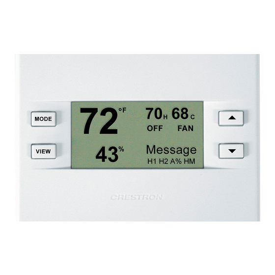
Operations and Installation Guide – DOC. 8163C The Main Screen displays the Current Temperature, System Mode, Fan Mode, and Set Point temperatures. The CHV-THSTAT also displays Relative Humidity. Press the up ▲arrow button to increase the set point temperature. Press the down ▼arrow button to decrease the set point temperature. - Page 62 Thermostats To Fan Mode 56 • Thermostats: CHV-TSTAT and CHV-THSTAT Crestron CHV-TSTAT and CHV-THSTAT NOTE: The Slab 2 System Mode screen offers HEAT and OFF choice only. Slab System Mode Screens Slab 1 System Mode Slab 3 System Mode Slab 5 System Mode Operations and Installation Guide –...
- Page 63 Use the up ▲and down ▼arrow buttons to select ENABLED or DISABLED. 4. Crestron System Pressing the MODE button again displays the “Crestron Sys” screen. Use the up ▲and down▼arrow buttons to select ONLINE or HOLD. ONLINE – Data flows both ways, to and from the thermostat, enabling adjustment from a remote location.
-
Page 64: View Button
“SCRN OPTIONS” setup screen. NOTE: This is only a display and not for system activation. This display can be shown on either the CHV-TSTAT or the CHV-THSTAT. 3. Messages Press the VIEW button again to display the “Messages” screen. This screen allows the user to view any text messages sent from the control system (only when part of a Cresnet system). -
Page 65: Programming Software
The program output of D3 Pro is a SIMPL Windows program with much of the functionality encapsulated in macros. Therefore, extending the capabilities of the system is very easy. Crestron D3 Pro and SIMPL Windows are intended for users with different levels of programming knowledge. The flexibility of each is proportional to the degree of programming expertise (i.e., the more flexible, the more... -
Page 66: Programming With Crestron D3 Pro
SIMPL Windows. Crestron D3 Pro then programs the system, including all control system logic. Crestron D3 Pro is fully integrated with the Crestron suite of software development tools and accesses these tools behind the scenes, enabling you to easily create robust systems. -
Page 67: C2Net-Device Slot In Configuration Manager
Crestron CHV-TSTAT and CHV-THSTAT C2Net-Device Slot in Configuration Manager To incorporate a CHV-TSTAT or CHV-THSTAT into the system, drag the symbol for the thermostat from the Crestron Sensing Modules folder of the Device Library and drop it on C2NET-Device slot in System Views. The PRO2 system tree displays the thermostat symbol in Slot 9, with a default Net ID of 2A as shown in the example graphic below. - Page 68 The following are detail views of the six thermostat slots in the SIMPL windows symbol. Definitions of the symbol inputs and outputs follow each diagram. 62 • Thermostats: CHV-TSTAT and CHV-THSTAT Crestron CHV-TSTAT and CHV-THSTAT Slot 1 – Heat Cool Control Slot 2 –...
- Page 69 Crestron CHV-TSTAT and CHV-THSTAT Thermostats Slot 1 Detail View - Heat/Cool Control Thermostats: CHV-TSTAT and CHV-THSTAT • 63 Operations and Installation Guide – DOC. 8163C...
- Page 70 FanAuto FanOn_F Output FanAuto_F OutdoorTempInput Input Continued on the following page 64 • Thermostats: CHV-TSTAT and CHV-THSTAT Crestron CHV-TSTAT and CHV-THSTAT SIGNAL DEFINITION TYPE Digital Raises (+) or lowers (-) the temperature regulating setpoint for heat-only, cool-only and single point auto mode, on the rising edge of the input.
- Page 71 If two temperature sensors are connected to the Remote 2 channel, this is the mean temperature. The Remote 2 sensor readings are reported regardless of the Use/Omit/OD/Slab designation. Thermostats: CHV-TSTAT and CHV-THSTAT • 65 Thermostats...
- Page 72 Thermostats Slot 1- Heat/Cool Control Digital Joins - continued SIGNAL Outdoor Temp Output Slot 2 Detail View – Humidity Control 66 • Thermostats: CHV-TSTAT and CHV-THSTAT Crestron CHV-TSTAT and CHV-THSTAT SIGNAL DEFINITION TYPE Analog Reports the temperature reading of any sensors set to "OD"...
- Page 73 "Use", in whole numbers. Only active when a thermostat setup has humidity sensing capability, either by being a CHV-THSTAT or a CHV-TSTAT with humidity remote. Humidity sensors are manually set to Use, Omit, or Outdoor via the setup menus on the thermostat.
- Page 74 Slot 2 – Humidity Control (continued) SIGNAL Remote2Humidity Output OutdoorHumidity Output Slot 3 Detail View – Slab Control 68 • Thermostats: CHV-TSTAT and CHV-THSTAT Crestron CHV-TSTAT and CHV-THSTAT SIGNAL DEFINITION TYPE Analog Reports the humidity reading of the Remote 2 humidity sensor in whole numbers.
- Page 75 If more than one sensor is set to "Slab", this is the mean slab temperature. Sensors are set to Use, Omit, OD (Outdoor) or Slab via the setup menus on the thermostat. Thermostats: CHV-TSTAT and CHV-THSTAT • 69 Thermostats...
- Page 76 Heat2Call Output AuxHeatCall Output Cool1Call Output Continued on the following page 70 • Thermostats: CHV-TSTAT and CHV-THSTAT Crestron CHV-TSTAT and CHV-THSTAT SIGNAL DEFINITION TYPE Analog Reports the maximum slab temperature value. The scale (Fahrenheit or Celsius) is based on the current setting in the unit.
- Page 77 High/1 = Humidifier running; Low/0 = System not running Digital Goes high when the system calls for slab heat. Remains high for as long as the slab system is running. High/1 = Slab heat running; Low/0 = System not running Thermostats: CHV-TSTAT and CHV-THSTAT • 71 Thermostats...
- Page 78 BtnLabel1 Input BtnLabel2 Input Continued on the following page 72 • Thermostats: CHV-TSTAT and CHV-THSTAT Crestron CHV-TSTAT and CHV-THSTAT DEFINITION Digital Alternately flashes the text "View Msg" with "Online/Hold, Net Fault" on the Main page of the thermostat LCD, for as long as the input remains high.
- Page 79 The thermostat LCD provides two Remote pages in which the Up and Down pushbuttons operate as remote function buttons. In this mode the buttons can trigger non-HVAC "remote" functions such as AV control, lighting, or alarm activation. Thermostats: CHV-TSTAT and CHV-THSTAT • 73 Thermostats...
- Page 80 SIGNAL TYPE RemoteBtn4_Press Output MsgWaiting Output 74 • Thermostats: CHV-TSTAT and CHV-THSTAT Crestron CHV-TSTAT and CHV-THSTAT DEFINITION Digital Indicates that Remote Function Button 4 (Down pushbutton) has been pressed on Remote page 2 of the thermostat LCD. Remains high for as long as the button is pressed.
- Page 81 Crestron CHV-TSTAT and CHV-THSTAT Slot 6 Detail View – System Configuration Continued on following page Operations and Installation Guide – DOC. 8163C Thermostats Thermostats: CHV-TSTAT and CHV-THSTAT • 75...
- Page 82 Thermostats Crestron CHV-TSTAT and CHV-THSTAT Slot 6 Detail View – System Configuration (continued) 76 • Thermostats: CHV-TSTAT and CHV-THSTAT Operations and Installation Guide – DOC. 8163C...
- Page 83 Run Fan in Heat Calls is a device setting that activates the fan output with W1/W2 heat calls. Does not enable operation on slab systems on the slab (W1) call. High/1 = Run Fan in Heat Calls enabled; Low/0 = Not enabled Thermostats: CHV-TSTAT and CHV-THSTAT • 77 Thermostats...
- Page 84 Output MainScrnOb_Outdoor MainScrnOb_Humidity MainScrnOb_SlabTemp RevSmodeDir Output Continued on the following page 78 • Thermostats: CHV-TSTAT and CHV-THSTAT Crestron CHV-TSTAT and CHV-THSTAT SIGNAL DEFINITION TYPE Digital Indicates that cold weather compensation has been enabled. Remains high for as long as the mode is enabled.
- Page 85 Reports the designator assigned to the local (internal) sensors. The CHV-TSTAT provides one internal temperature sensor; the CHV-THSTAT provides internal sensors for temperature and humidity. Each sensor must be designated as Use or Omit. Readings from local and remote sensors that have the same designator are averaged together.
-
Page 86: Example Programs
Output TempDispOffset Output AutoDeadband Output SlabRegulation Output Example Programs The example program for the thermostat is available from the Crestron FTP site (ftp://ftp.crestron.com/Examples). Search for CHV-THSTAT_with_5- 2_Scheduler_Sample_Program.zip. 80 • Thermostats: CHV-TSTAT and CHV-THSTAT Crestron CHV-TSTAT and CHV-THSTAT SIGNAL DEFINITION TYPE Analog Reports the interstage differential in tenths of a degree. -
Page 87: Viewport Id String
- SLAB 1 system with slab regulation index 3 (SB1;SRG3;) - Offset of 0C (OS0.0;) - Half C units (C05;) 2B: CHV-THSTATA [v2.0, #D8000000] (SB1;SRG3;OS0.0;C05;OUSOOO;SETUP) Refer to the following chart for ID string definitions. Operations and Installation Guide – DOC. 8163C Thermostats Thermostats: CHV-TSTAT and CHV-THSTAT • 81... - Page 88 NOTE: If you have restored a version 1.0 or 1.1 setup in this power cycle, an R appears after the word SETUP. 82 • Thermostats: CHV-TSTAT and CHV-THSTAT Crestron CHV-TSTAT and CHV-THSTAT DESCRIPTION Heat/cool, heat pump, or slab system...
-
Page 89: Viewport Error Log Message Formats
CHA errors/CHB errors are the number of errors on each sub-channel cycle count is the number of read cycles that have occurred. Error: Message from device Slot-09.ID-2A: Sensor R1T type OD: 2,3 Errors @ 3922 (0056:0000:0056) Thermostats: CHV-TSTAT and CHV-THSTAT • 83 Thermostats... -
Page 90: Local Error Messages
LINE and VIEW MSG. The thermostat messages are shown as follows in descending priority. NOTE: All of these conditions are self-healing if the sensor begins sending valid data. 84 • Thermostats: CHV-TSTAT and CHV-THSTAT Crestron CHV-TSTAT and CHV-THSTAT ERROR DESCRIPTION... -
Page 91: Problem Solving
Crestron CHV-TSTAT and CHV-THSTAT Problem Solving Troubleshooting The table below provides corrective action for possible trouble situations. If further assistance is required, please contact a Crestron customer service representative. CHV-TSTAT/CHV-THSTAT Troubleshooting Troubleshooting continued on following page Operations and Installation Guide – DOC. 8163C... - Page 92 Thermostats Troubleshooting continued 86 • Thermostats: CHV-TSTAT and CHV-THSTAT Crestron CHV-TSTAT and CHV-THSTAT TROUBLE POSSIBLE CAUSE(S) Wide temperature Auto deadband variance in single- setting too high setpoint auto mode Heating/Cooling not 20-minute system operating in single- toggling lockout setpoint auto mode...
-
Page 93: Further Inquiries
Crestron's award winning customer service team by calling: You can also log onto the online help section of the Crestron website (www.crestron.com) to ask questions about Crestron products. First-time users will need to establish a user account to fully benefit from all available features. -
Page 94: Appendix A: Glossary
Humidity – The total amount of moisture in air. Relative humidity (RH) is the HVAC – Heating, ventilation and air conditioning. Interstage Differential – The proportional temperature error (0.5 to 3.0º) to trigger 88 • Thermostats: CHV-TSTAT and CHV-THSTAT Crestron CHV-TSTAT and CHV-THSTAT appropriate system before reaching the set point. - Page 95 (W1) call. restart for three minutes. operates at a fraction of its capacity. When the temperature outside goes very low, the system adjusts to full capacity (second stage) to meet the demand. 99°F. Thermostats: CHV-TSTAT and CHV-THSTAT • 89 Thermostats...
-
Page 96: Appendix B: About Heat Pumps
90 • Thermostats: CHV-TSTAT and CHV-THSTAT Crestron CHV-TSTAT and CHV-THSTAT Operations and Installation Guide – DOC. 8163C... -
Page 97: Return And Warranty Policies
CRESTRON shall not be liable to honor the terms of this warranty if the product has been used in any application other than that for which it was intended, or if it has been subjected to misuse, accidental damage, modification, or improper installation procedures. - Page 98 Thermostats Crestron CHV-TSTAT and CHV-THSTAT This page intentionally left blank. 92 • Thermostats: CHV-TSTAT and CHV-THSTAT Operations and Installation Guide – DOC. 8163C...
- Page 99 Crestron CHV-TSTAT and CHV-THSTAT Thermostats This page intentionally left blank. Thermostats: CHV-TSTAT and CHV-THSTAT • 93 Operations and Installation Guide – DOC. 8163C...
- Page 100 Crestron Electronics, Inc. Operations and Installation Guide – DOC. 8163C 15 Volvo Drive Rockleigh, NJ 07647 08.04 Tel: 888.CRESTRON Fax: 201.767.7576 Specifications subject to www.crestron.com change without notice.
Need help?
Do you have a question about the CHV-THSTAT and is the answer not in the manual?
Questions and answers
what does net fault mean on control panel
Thermostat setting often reverts to 70 degrees for no apparent reason. This is erratic and I **** observing and operating if rom a remote location. Two other thermostats don't do this. Is this a reset to a default setting?