
Related Manuals for Crestron CHV-TSTAT-FCU-HOTEL


Summary of Contents for Crestron CHV-TSTAT-FCU-HOTEL
- Page 1 Crestron CHV-TSTAT-FCU-HOTEL Heating and Cooling Thermostat (Fan Coil Unit) Operations & Installation Guide...
-
Page 2: Regulatory Compliance
Crestron disclaims any proprietary interest in the marks and names of others. Crestron is not responsible for errors in typography or photography. -
Page 3: Table Of Contents
Physical Description ....................6 Setup ............................10 Network Wiring ......................10 Identity Code ......................10 Installation ......................... 11 Wiring the CHV-TSTAT-FCU-HOTEL ..............14 Uploading and Upgrading ......................16 Establishing Communication ..................16 Programs and Firmware .................... 17 Program Checks ......................17 Thermostat Setup ........................ -
Page 5: Heating And Cooling Thermostat (Fan Coil Unit): Chv-Tstat-Fcu-Hotel
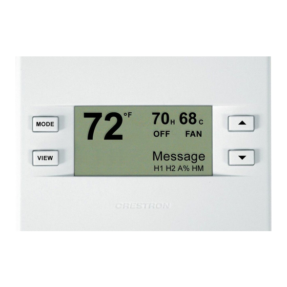
CHV-TSTAT-FCU-HOTEL ® delivers enhanced functionality as part of a complete Crestron automation system. Integrating HVAC with a Crestron system can help lower energy bills and increase user friendliness. The large backlit LCD display provides a clear view of temperature, setpoint, system mode, fan mode, system status, and setup functions. -
Page 6: Features And Functions
CHV-TSTAT-FCU-HOTEL has custom firmware, display programming, and terminal labels designed for 3-speed fan applications. The CHV-TSTAT-FCU-HOTEL supports on/off control of the valves and the fan in 4-pipe fan coil applications, eliminating the need for an additional device dedicated to controlling the fan coil unit itself. -
Page 7: Remote Sensors
These settings allow HVAC contractors to install and test the thermostats prior to the appearance of a Crestron system integrator. When connected to a control system, setting the ID of each device employs the same convention as Crestron's familiar TSID (touch-settable ID) method. -
Page 8: Specifications
Thermostat (Fan Coil Unit) Crestron CHV-TSTAT-FCU-HOTEL Specifications Specifications for the CHV-TSTAT-FCU-HOTEL are listed in the following table. CHV-TSTAT-FCU-HOTEL Specifications SPECIFICATION DETAILS Measurement Range Indoor Temperature 0° to 110° F (-18° to 43° C) Outdoor Temperature -40º to 170º F (-40º to 77º C) - Page 9 CRESNET-HP-NP- Cresnet "High-Power" Control [BK,OR,TL] Cable, non-plenum CRESNET-NP- Cresnet Control Cable, [BK,OR,TL,YL] non-plenum CRESNET-P- Cresnet Control Cable, plenum [BK,OR,TL,YL] * Requires CHV-RTHS Remote Temperature and Humidity Sensor (sold separately). Operations & Installation Guide – DOC. 7543A Thermostat: CHV-TSTAT-FCU-HOTEL • 5...
-
Page 10: Physical Description
Thermostat (Fan Coil Unit) Crestron CHV-TSTAT-FCU-HOTEL Physical Description This section provides information on the connections, controls, and indicators available on the CHV-TSTAT-FCU-HOTEL. CHV-TSTAT-FCU-HOTEL Overall Dimensions (Front View) 5.00 in (127 mm) 3.75 in (96 mm) 6 • Thermostat: CHV-TSTAT-FCU-HOTEL Operations & Installation Guide – DOC. 7543A... - Page 11 Crestron CHV-TSTAT-FCU-HOTEL Thermostat (Fan Coil Unit) CHV-TSTAT-FCU-HOTEL Overall Dimensions (Front and Side Views) 1.04 in 3.27 in (27 mm) (84 mm) CHV-TSTAT-FCU-HOTEL Backplate (Front Cover Removed) NETWORK Operations & Installation Guide – DOC. 7543A Thermostat: CHV-TSTAT-FCU-HOTEL • 7...
- Page 12 RSR: Remote Sensor Return RS1: Remote Sensor Terminal – Connect the sensor from RS1 to RSR RS2: Remote Sensor Terminal – Connect the sensor from RS2 to RSR (Continued on following page) 8 • Thermostat: CHV-TSTAT-FCU-HOTEL Operations & Installation Guide – DOC. 7543A...
- Page 13 R: Return for system call LO: Calls for low fan speed MED: Calls for medium fan speed HI: Calls for high fan speed W: Calls for heat Y: Calls for cool Operations & Installation Guide – DOC. 7543A Thermostat: CHV-TSTAT-FCU-HOTEL • 9...
-
Page 14: Setup
NOTE: The latest software can be downloaded at www.crestron.com/software. The Net ID of the CHV-TSTAT-FCU-HOTEL has been factory set to 2A. The Net IDs of multiple CHV-TSTAT-FCU-HOTEL devices in the same system must be unique. Net IDs are changed from a personal computer (PC) via Crestron Toolbox™... -
Page 15: Installation
Crestron CHV-TSTAT-FCU-HOTEL Thermostat (Fan Coil Unit) Installation The CHV-TSTAT-FCU-HOTEL is supplied with two #06-32 x 1 in (26 mm) pan head screws (2007251). NOTE: Installers should have a strong working knowledge of HVAC systems. The location of the thermostat can affect its performance and efficiency. - Page 16 4. Make sure unit is correctly oriented and place it in the electrical box. 5. Attach the CHV-TSTAT-FCU-HOTEL rear plate to the electrical box using the two included #06-32 x 1 in (26 mm) pan head screws. Screws and wall anchors can also be used to attach the rear plat directly to a wall.
- Page 17 4. Make sure unit is correctly oriented and attach the CHV-TSTAT-FCU-HOTEL rear plate to the wall using screws and wall anchors. CAUTION: Do not press on the LCD display during mounting, as this may cause the screen to crack.
-
Page 18: Wiring The Chv-Tstat-Fcu-Hotel
A small flat head screwdriver (not supplied) is required to attach the control wires from the HVAC system. Apply power after all connections have been made. Connections for the CHV-TSTAT-FCU-HOTEL RSR: Remote Sensor Return RSR: Remote Sensor Return... - Page 19 Thermostat (Fan Coil Unit) Wiring the CHV-TSTAT-FCU-HOTEL Reference Power Cool Valve NETWORK Heat Valve Fan High Fan Medium Fan Low Wiring the CHV-RTS and Cresnet Connections CHV-RTS To Cresnet NETWORK Operations & Installation Guide – DOC. 7543A Thermostat: CHV-TSTAT-FCU-HOTEL • 15...
-
Page 20: Uploading And Upgrading
(such as changing the device ID or creating an IP table) to ensure proper functioning. NOTE: Crestron software and any files on the website are for authorized Crestron dealers and Crestron Service Providers (CSPs) only. New users must register to obtain access to certain areas of the site (including the FTP site). -
Page 21: Programs And Firmware
Crestron Studio help file, SIMPL Windows help file, or the Crestron Toolbox help file. If a Crestron Studio (or SIMPL Windows) program is provided, it can be Crestron uploaded to the control system using Crestron Studio (or SIMPL Studio or Windows) or Crestron Toolbox. -
Page 22: Thermostat Setup
CRESTRON Press and hold FAN and ºF / ºC simultaneously for 2 seconds to exit Setup mode. NOTE: Refer to “Wiring the CHV-TSTAT-FCU-HOTEL to the HVAC System” on page 12 for remote sensor connections to the thermostat. “SETUP: SYSTEM” Screen... - Page 23 Call FAN in HUM makes a fan call during any humidity call. This prevents the need to wait for a heating or cooling call to trigger the fan. NOTE: Most dehumidifier applications automatically trigger fan operation. Operations & Installation Guide – DOC. 7543A Thermostat: CHV-TSTAT-FCU-HOTEL • 19...
- Page 24 Network ID: LCD Contrast match the network ID set for the thermostat Short Cycle Prot: 180s in Crestron Studio or SIMPL Windows. CHV-THSTAT-FCU-HOTEL [v2.070.0346, #00000000] LCD Contrast controls the brightness of the LCD screen. Select 1 – 10 to lighten or darken the screen.
- Page 25 The sensors are used for >TEMP HUM INTERNAL: temperature and humidity averaging. REMOTE 1: Choose USE to include the sensor or OMIT REMOTE 2: to exclude the sensor in the averaging Operations & Installation Guide – DOC. 7543A Thermostat: CHV-TSTAT-FCU-HOTEL • 21...
- Page 26 (F) for RS2. LOW/HI F displays the low and high temperature (F) for RS1 followed by the low and high temperature (F) for RS2. 22 • Thermostat: CHV-TSTAT-FCU-HOTEL Operations & Installation Guide – DOC. 7543A...
- Page 27 Press and hold FAN and ºF / ºC for 2 seconds to exit Setup mode. NOTE: Exit is not possible if the sensor setup does not meet system requirements. Operations & Installation Guide – DOC. 7543A Thermostat: CHV-TSTAT-FCU-HOTEL • 23...
-
Page 28: Thermostat Operation
▼ arrow button to decrease the setpoint temperature. NOTE: The first press of the up ▲ and down ▼ arrow buttons triggers backlight. NOTE: System indicators flash to indicate short cycle timer protection (timer guards) engaged. 24 • Thermostat: CHV-TSTAT-FCU-HOTEL Operations & Installation Guide – DOC. 7543A... -
Page 29: Problem Solving
Crestron CHV-TSTAT-FCU-HOTEL Thermostat (Fan Coil Unit) Problem Solving Troubleshooting The following table provides corrective action for possible trouble situations. If further assistance is required, please contact a Crestron customer service representative. CHV-TSTAT-FCU-HOTEL Troubleshooting TROUBLE POSSIBLE CORRECTIVE CAUSE(S) ACTION The display is... - Page 30 Setup,” on page 18. disabled or have failed. There is poor Recheck wiring communications connections. between Use low capacitance thermostat and twisted-pair wiring. furnace or boiler. (Continued on following page) 26 • Thermostat: CHV-TSTAT-FCU-HOTEL Operations & Installation Guide – DOC. 7543A...
- Page 31 Net ID address included Correct the Net ID in in the system. the program (if required). (Continued on following page) Operations & Installation Guide – DOC. 7543A Thermostat: CHV-TSTAT-FCU-HOTEL • 27...
-
Page 32: Check Network Wiring
Check Network Wiring To ensure optimum performance over the full range of the installation Use the topology, use Crestron Certified Wire only. Failure to do so may incur Right Wire additional charges if support is required to identify performance deficiencies because of using improper wire. -
Page 33: Reference Documents
For example, a Cresnet run using 18 AWG Crestron Certified Wire and drawing 20 watts should not have a length of run more than 333 feet (101 meters). If Cresnet HP is used for the same run, its length could extend to 1250 feet (381 meters). -
Page 34: Further Inquiries
[1-888-273-7876] or, for assistance within a particular geographic region, refer to the listing of Crestron worldwide offices at www.crestron.com/offices. To post a question about Crestron products, log onto Crestron’s Online Help at www.crestron.com/onlinehelp. First-time users must establish a user account to fully benefit from all available features. -
Page 35: Return And Warranty Policies
(property or economic damages inclusive) arising from the sale or use of this equipment. Crestron is not liable for any claim made by a third party or made by the purchaser for a third party. - Page 36 Crestron Electronics, Inc. Guide – DOC. 7543A Operations & Installation 15 Volvo Drive Rockleigh, NJ 07647 (2037049) Tel: 888.CRESTRON 04.14 Fax: 201.767.7576 Specifications subject to www.crestron.com change without notice.
Need help?
Do you have a question about the CHV-TSTAT-FCU-HOTEL and is the answer not in the manual?
Questions and answers