
Related Manuals for Crestron CHV-TSTATEX-FCU


Summary of Contents for Crestron CHV-TSTATEX-FCU
- Page 1 Crestron CHV-TSTATEX-FCU ® infiNET EX Thermostat (Fan Coil Unit) Operations & Installation Guide...
-
Page 2: Regulatory Compliance
Crestron Electronics, Inc. in the United States and/or other countries. Other trademarks, registered trademarks, and trade names may be used in this document to refer to either the entities claiming the marks and names or their products. Crestron disclaims any proprietary interest in the marks and names of others. -
Page 3: Table Of Contents
Identity Code ....................... 9 Supplied Hardware ...................... 9 Installation ........................9 DIP Switch Setup ...................... 11 Wiring the CHV-TSTATEX-FCU to the HVAC System.......... 12 Basic Setup ..........................16 Basic Thermostat Setup ..................... 16 Joining an infiNET EX Network ................16 Leaving an infiNET EX Network ................ -
Page 5: Infinet Ex Thermostat (Fan Coil Unit): Chv-Tstatex-Fcu
Crestron automation system. Integrating HVAC with a Crestron system can help lower energy bills and increase user friendliness. The CHV-TSTATEX-FCU is designed for fan coil unit HVAC systems. The large backlit LCD display provides a clear view of temperature, setpoint, system mode, fan mode, system status, and setup functions. - Page 6 RF conditions. 1. 4- pipe fan coil units are supported. 2. CHV-TSTATEX-FCU must be powered by a 24 volt source to enable repeater functionality. 2 • infiNET EX Thermostat (Fan Coil Unit): CHV-TSTATEX-FCU Operations & Installation Guide – DOC. 7206C...
-
Page 7: Specifications
CHV-TSTATEX to be installed out of view. For heat pump-type systems, outdoor temperature can be monitored to optimize system performance. Compatible sensors include the CHV-RTS and the CHV-RSS (both sold separately). Specifications Specifications for the CHV-TSTATEX-FCU are listed in the following table. CHV-TSTATEX-FCU Specifications SPECIFICATION DETAILS... - Page 8 Remote Slab Sensor and Outdoor Temperature Sensor CHV-RTS Remote Temperature Sensor CLW-EXPEX-GD-W-T infiNET EX Wireless Expander, Ground Pin Down, White Textured 3-Series Control System 4 • infiNET EX Thermostat (Fan Coil Unit): CHV-TSTATEX-FCU Operations & Installation Guide – DOC. 7206C...
-
Page 9: Physical Description
CHV-TSTATEX-FCU. CHV-TSTATEX-FCU Physical View CHV-TSTATEX-FCU Overall Dimensions (Front and Side Views) 5.53 in 1.03 in (141 mm) (26 mm) 4.50 in (115 mm) Operations & Installation Guide – DOC. 7206C infiNET EX Thermostat (Fan Coil Unit): CHV-TSTATEX-FCU • 5... - Page 10 EX Thermostat (Fan Coil Unit) Crestron CHV-TSTATEX-FCU CHV-TSTATEX-FCU Overall Dimensions (Rear View) 27 in (83 mm) CHV-TSTATEX-FCU (Connection View, Front with Cover Removed) 6 • infiNET EX Thermostat (Fan Coil Unit): CHV-TSTATEX-FCU Operations & Installation Guide – DOC. 7206C...
- Page 11 RS2: Remote sensor (2) (outdoor) RS1: Remote sensor (1) (indoor) RSR: Remote sensor return RSR: Remote sensor return N/C: Unused Heat N/C: Unused (Continued on following page) Operations & Installation Guide – DOC. 7206C infiNET EX Thermostat (Fan Coil Unit): CHV-TSTATEX-FCU • 7...
- Page 12 11 for details Power Switch (1) Two-position slide switch used to configure power settings; Refer to “DIP Switch Setup” which starts on page 11 for details 8 • infiNET EX Thermostat (Fan Coil Unit): CHV-TSTATEX-FCU Operations & Installation Guide – DOC. 7206C...
-
Page 13: Setup
Control System requires a unique RF ID. The RF ID is a two-digit hexadecimal number that can range from 03 to FF. The RF ID of the unit, set using Crestron Toolbox™, must match the RF ID specified in the Crestron Studio or SIMPL Windows program. - Page 14 NOTE: Crestron has provided small slots on either side of the battery cover, designed to allow a flat head screwdriver to be inserted to assist in removal.
-
Page 15: Dip Switch Setup
Single setpoint Dual setpoint By default, the CHV-TSTATEX-FCU is configured to be powered by two AA alkaline batteries. To extend battery life, the device also receives power from the HVAC system by drawing a small amount of current through the heat or cool terminals. -
Page 16: Wiring The Chv-Tstatex-Fcu To The Hvac System
HVAC systems. If the system being connected does not match any of the systems described below, contact Crestron Technical Support for assistance. 12 • infiNET EX Thermostat (Fan Coil Unit): CHV-TSTATEX-FCU Operations & Installation Guide – DOC. 7206C... - Page 17 NOTE: 24 volt power is returned through the R connector. Refer to wiring diagrams on the following pages. NOTE: Refer to “DIP Switch Setup” which starts on page 11 for DIP switch settings. Operations & Installation Guide – DOC. 7206C infiNET EX Thermostat (Fan Coil Unit): CHV-TSTATEX-FCU • 13...
- Page 18 EX Thermostat (Fan Coil Unit) Crestron CHV-TSTATEX-FCU CHV-TSTATEX-FCU Wiring Diagram Heat Pipe Valve Cool Pipe Valve Fan High Relay Fan Med Relay Fan Low Relay System Transformer Optional 14 • infiNET EX Thermostat (Fan Coil Unit): CHV-TSTATEX-FCU Operations & Installation Guide – DOC. 7206C...
- Page 19 Crestron CHV-TSTATEX-FCU infiNET EX Thermostat (Fan Coil Unit) CHV-TSTATEX-FCU Sensor Wiring CHV-RTS Operations & Installation Guide – DOC. 7206C infiNET EX Thermostat (Fan Coil Unit): CHV-TSTATEX-FCU • 15...
-
Page 20: Basic Setup
Joining an infiNET EX Network Before a CHV-TSTATEX-FCU can be used on an infiNET EX network, it must first join an infiNET EX network by being acquired by an infiNET EX gateway (e.g., CEN-RFGW-EX). -
Page 21: Leaving An Infinet Ex Network
5 seconds. Press MODE until the unacquire function is displayed (UA). Press on the CHV-TSTATEX-FCU to start the unacquire process. Refer to “Verifying Communication Status” on page 21 for a list of codes displayed once the process is completed. Press FAN on the thermostat to exit Setup mode. -
Page 22: Advanced Setup
Advanced Setup Setup Mode After the CHV-TSTATEX-FCU is installed, it is necessary to set it up for a particular heating/cooling system. Please note that some of the setup parameters listed below are not always shown since they are dependent upon other thermostat settings. -
Page 23: Setup Mode Parameters/Functions
EX Thermostat (Fan Coil Unit) NOTE: While in Setup mode, a period of one minute with no button activity causes the CHV-TSTATEX-FCU to revert to standard operation, unless a function (such as an infiNET EX acquire) is executing. Setup Mode Parameters/Functions The following table shows the available setup parameters/functions. - Page 24 Finished (00) button for three seconds for this function to Button not held execute long enough (Er) (Continued on following page) 20 • infiNET EX Thermostat (Fan Coil Unit): CHV-TSTATEX-FCU Operations & Installation Guide – DOC. 7206C...
-
Page 25: Verifying Communication Status
GW found but rejected device Radio operation not Radio operation not available available Radio operation not available Network communication not possible Device not joined to a gateway Operations & Installation Guide – DOC. 7206C infiNET EX Thermostat (Fan Coil Unit): CHV-TSTATEX-FCU • 21... -
Page 26: Self-Test Results
Often associated with excessive network hops; communication communications link Consider moving device closer to gateway or splitting network with additional gateways for better coverage 22 • infiNET EX Thermostat (Fan Coil Unit): CHV-TSTATEX-FCU Operations & Installation Guide – DOC. 7206C... -
Page 27: Operation
EX Thermostat (Fan Coil Unit) Operation System Mode The MODE button on the CHV-TSTATEX-FCU cycles the unit through all available system modes in the following order: Off, Heat, Emergency Heat (for heat pump and dual-fuel systems), Cool and Auto (if enabled in Setup). -
Page 28: Fan
Both the heat and cool setpoints can be viewed simultaneously using a touch screen. NOTE: When using a Dual setpoint, the CHV-TSTATEX-FCU has a 20 minute change limiter to prevent system toggling. Single Setpoint Auto Mode (“AU” = “S” in Setup Mode) In single setpoint Auto mode, a single setpoint is used for regulation at all times, regardless of whether the system is heating or cooling. -
Page 29: Hold
Setpoint” which can be specified by the control system program. This is handled automatically by the “Crestron CHV-TSTATEX-FCU w/5-2 Scheduler” module provided with the Crestron Database. Refer to the Crestron Studio help file or the SIMPL Windows help file for details. -
Page 30: Lcd Display
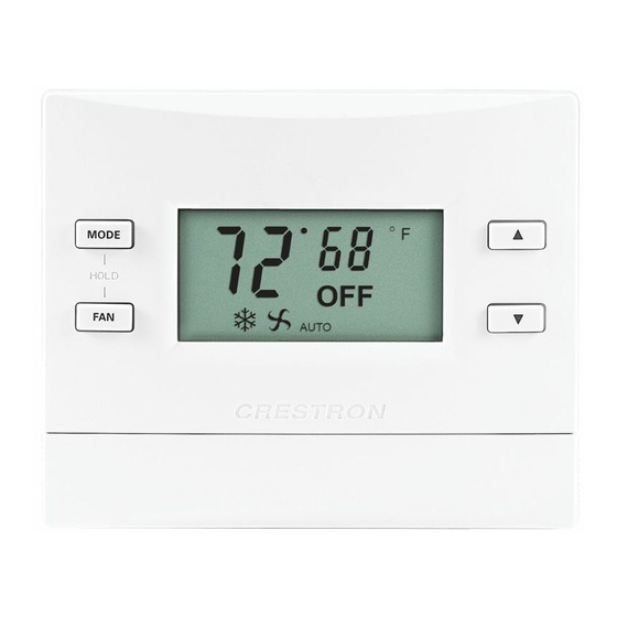
If the thermostat is wired to have the optional 24 Vac at the 24C terminal and the power switch is set for 24 V, there is no delay in feedback. LCD Display CHV-TSTATEX-FCU LCD Display AUTO HOLD 26 • infiNET EX Thermostat (Fan Coil Unit): CHV-TSTATEX-FCU Operations & Installation Guide – DOC. 7206C... - Page 31 F – Displayed whenever a Fan Call is being made When the CHV-TSTATEX-FCU detects a low battery condition (approximately one month of battery life remaining), the display alternates “Lo” in place of the ambient temperature once per second. Operations & Installation Guide – DOC. 7206C...
-
Page 32: Uploading And Upgrading
(such as changing the device ID or creating an IP table) to ensure proper functioning. NOTE: Crestron software and any files on the website are for authorized Crestron dealers and Crestron Service Providers (CSP) only. New users must register to obtain access to certain areas of the site (including the FTP site). -
Page 33: Programs And Firmware
Toolbox. For details on uploading and upgrading, refer to the Crestron Studio help file, the SIMPL Windows help file, or the Crestron Toolbox help file. If a Crestron Studio or SIMPL Windows program is provided, it can be uploaded to Crestron Studio / the control system using Crestron Studio, SIMPL Windows or Crestron Toolbox. -
Page 34: Problem Solving
EX Thermostat (Fan Coil Unit) Crestron CHV-TSTATEX-FCU Problem Solving Troubleshooting The following table provides corrective action for possible trouble situations. If further assistance is required, please contact a Crestron customer service representative. CHV-TSTATEX-FCU Troubleshooting TROUBLE POSSIBLE CORRECTIVE ACTION CAUSE(S) Check for 24 Vac on 24C connector. - Page 35 “S” (for single setpoint operation) or “d” (for dual setpoint operation) (refer to “Setup Mode Parameters/Functions” which starts on page 19). (Continued on following page) Operations & Installation Guide – DOC. 7206C infiNET EX Thermostat (Fan Coil Unit): CHV-TSTATEX-FCU • 31...
- Page 36 AA batteries are device does not causing problems installed. indicate a heat with HVAC or cool call. system. Improper wiring Recheck wiring connections. connections. 32 • infiNET EX Thermostat (Fan Coil Unit): CHV-TSTATEX-FCU Operations & Installation Guide – DOC. 7206C...
-
Page 37: Reference Documents
Crestron worldwide offices on the Crestron Web site (www.crestron.com/offices) for assistance within a particular geographic region. To post a question about Crestron products, log onto the Online Help section of the Crestron Web site (www.crestron.com/onlinehelp). First-time users must establish a user account to fully benefit from all available features. -
Page 38: Glossary
The user selectable temperature the system maintains. Time Delay (Timer Guards) Refers to a safety device or circuit that does not allow restart for 3 minutes. 34 • infiNET EX Thermostat (Fan Coil Unit): CHV-TSTATEX-FCU Operations & Installation Guide – DOC. 7206C... -
Page 39: Return And Warranty Policies
(property or economic damages inclusive) arising from the sale or use of this equipment. Crestron is not liable for any claim made by a third party or made by the purchaser for a third party. - Page 40 Crestron Electronics, Inc. Operations & Installation Guide – DOC. 7206C 15 Volvo Drive Rockleigh, NJ 07647 (2031609) Tel: 888.CRESTRON 01.13 Fax: 201.767.7576 Specifications subject to www.crestron.com change without notice.
Need help?
Do you have a question about the CHV-TSTATEX-FCU and is the answer not in the manual?
Questions and answers