Crestron CHV-TSTAT Operation And Installation Manual
Crestron electronics operations guide thermostat chv-tstat, chv-thstat
Hide thumbs
Also See for CHV-TSTAT:
- Operation and installation manual (44 pages) ,
- Dimension manual (38 pages) ,
- Quick start manual (4 pages)

Related Manuals for Crestron CHV-TSTAT


Summary of Contents for Crestron CHV-TSTAT
- Page 1 Crestron CHV-TSTAT & CHV-THSTAT Thermostats Operations and Installation Guide Firmware Version 1.1 and Earlier...
- Page 2 This document was prepared and written by the Technical Documentation department at: Crestron Electronics, Inc. 15 Volvo Drive Rockleigh, NJ 07647 1-888-CRESTRON All brand names, product names and trademarks are the property of their respective owners. ©2004 Crestron Electronics, Inc.
-
Page 3: Table Of Contents
Crestron CHV-TSTAT and CHV-THSTAT Contents Quick Installation Reference ...ii Thermostats: CHV-TSTAT and CHV-THSTAT Introduction ... 1 Functions and Features ... 1 Specifications ... 3 Physical Description... 4 Industry Compliance ... 6 Setup ... 7 Network Wiring... 7 Identity Code ... 7 System Connections ... -
Page 4: Quick Installation Reference
2. Separate the thermostat from the backplate to expose the connections and mounting holes. 3. Mount the thermostat backplate (60 inches above the finished floor) directly to the wall with wall anchors (not provided) and screws (not provided) or to a single-gang box (not provided) mounted horizontally, and connect the wiring. -
Page 5: Thermostats: Chv-Tstat And Chv-Thstat
CHV-THSTAT Introduction Functions and Features The CHV-TSTAT and CHV-THSTAT series are wall-mounted universal thermostats that can be part of a Crestron Home capable of controlling one or two-stage heating and cooling systems. Each thermostat is available in three colors: almond, black and white. The suffix ‘A’, ‘B’, and ‘W’, respectively denotes color, e.g., CHV-TSTATB is a black unit. -
Page 6: Remote Sensors
RTS & CHV-RTHS Installation Guide (Doc. 8189), which is available from the Crestron website (www.crestron.com). NOTE: The CHV-TSTAT and CHV-THSTAT allow the user to set a temperature that the heating and/or cooling system maintains. This is called the “Set Point”. Refer to “Operating the Thermostat”... -
Page 7: Specifications
Crestron CHV-TSTAT and CHV-THSTAT Specifications The following table provides a summary of specifications for the CHV-TSTAT and CHV-THSTAT. CHV-TSTAT and CHV-THSTAT Specifications Power Requirements Crestron power factor Default Network ID Control System Update Files LCD Display Screen Viewing Angles Humidity Range... -
Page 8: Physical Description
Thermostats Physical Description Refer to the illustrations below and on next page. The CHV-TSTAT and CHV- THSTAT are enclosed in a plastic enclosure with four buttons and an LCD display on the front. The back of the unit has ventilation slots, and holes for mounting the unit and wiring. - Page 9 Connection View (Backplate, view from the front with cover removed) Ports The CHV-TSTAT and CHV-THSTAT have four types of connections on the inside back plate (refer to graphic above). NETWORK (Optional) – provides communication to the control system and Cresnet power to the CHV-TSTAT and CHV-THSTAT.
-
Page 10: Industry Compliance
There are four buttons used to setup and adjust the thermostat. NOTE: When MODE and VIEW are pressed together and held for five seconds, the thermostat enters the system setup mode (refer to “Thermostat Setup” on page 17). Industry Compliance... -
Page 11: Setup
SIMPL Windows or D3 Pro program. Refer to “Device Options” on page 18 for a description of assigning the NET ID to the thermostat and “Setting the Net ID in Device Settings” on page 27 for an example of the SIMPL Windows procedure. -
Page 12: System Connections
Thermostats System Connections Backplate - view from the front with the cover removed 8 • Thermostats: CHV-TSTAT and CHV-THSTAT Crestron CHV-TSTAT and CHV-THSTAT HUM - Energized to RHU during humidity call RHU - Reference for humidifier RSR - Remote Sensor Returns - Common sensor terminal... -
Page 13: Wiring Diagrams
Crestron CHV-TSTAT and CHV-THSTAT Wiring Diagrams The wiring diagrams that follow show connections for the CHV-TSTAT and CHV- THSTAT. CAUTION: power method chosen, and is critical to proper operation. Improper P4 jumper position can cause equipment damage. NOTE: Ensure that the power circuits are shut off at the source before connecting the thermostat. -
Page 14: Separately Powered (By An Independent Transformer)
24 VAC 24(R) NOTE: The P4 jumper position is critical to proper operation and depends on the method used to power the thermostat. 10 • Thermostats: CHV-TSTAT and CHV-THSTAT Crestron CHV-TSTAT and CHV-THSTAT (by an independent transformer) 120 VAC Jumper on P4 between pins 2 and 3... -
Page 15: Three-Wire Heating System Connections
Crestron CHV-TSTAT and CHV-THSTAT Three-Wire Heating System Connections Backplate Thermostat Circuit Board Operations and Installation Guide – DOC. 8163B NETWORK CRESTRON ELECTRONICS Thermostats: CHV-TSTAT and CHV-THSTAT • 11 Thermostats Integrated Control Unit Jumper on P4 between pins 1 and 2... -
Page 16: Five-Wire Heating/Cooling System Connections
Thermostats Five-Wire Heating/Cooling System Connections Backplate Jumper From RH to RC Thermostat Circuit Board 12 • Thermostats: CHV-TSTAT and CHV-THSTAT Crestron CHV-TSTAT and CHV-THSTAT NETWORK CRESTRON ELECTRONICS Operations and Installation Guide – DOC. 8163B Integrated Control Unit Jumper on P4... -
Page 17: Heat Pump Connections (Single & Two-Stage)
Thermostat Circuit Board NOTE: For wiring details, refer to the general Heat Pump schematic on the following page. Operations and Installation Guide – DOC. 8163B NETWORK CRESTRON ELECTRONICS Thermostats: CHV-TSTAT and CHV-THSTAT • 13 Thermostats Integrated Control Unit Stage) Jumper on... - Page 18 Stage Compressor StageCompressor Changeover Valve Heat Pump Transformer 120 VAC 24 VAC Aux Heat Transformer Aux Heat Relay 120 VAC 24 VAC 14 • Thermostats: CHV-TSTAT and CHV-THSTAT Crestron CHV-TSTAT and CHV-THSTAT Operations and Installation Guide – DOC. 8163B Backplate NETWORK...
-
Page 19: Installation
Thermostats and sensors are mounted 60 inches (152.4 cm) above the finished floor (HVAC industry standard). Refer to the following illustrations. Do the following to install the CHV-TSTAT or the CHV-THSTAT. NOTE: When installing directly on drywall, use anchoring screws and hardware. - Page 20 Thermostats Installation View – Single gang electrical box – horizontal mounting NOTE: Install insulation in the gang box to prevent inaccurate readings. 16 • Thermostats: CHV-TSTAT and CHV-THSTAT Crestron CHV-TSTAT and CHV-THSTAT Panhead 6/32 x 1 in Installation view – Direct mount to wall...
-
Page 21: Thermostat Setup And Operation
Crestron CHV-TSTAT and CHV-THSTAT Thermostat Setup and Operation Setup Procedure After the thermostat is installed, it is necessary to set it up. Follow these directions. Press and hold the MODE and VIEW buttons simultaneously for five seconds to access the setup menus. -
Page 22: System Performance
Disp Humidity Pgs? Cold Weather Comp? Run Fan in Ht Calls? VIEW CRESTRON 18 • Thermostats: CHV-TSTAT and CHV-THSTAT Crestron CHV-TSTAT and CHV-THSTAT Anticipators (valid selections are 1 through 6) Low number = more frequent cycles and faster response (tighter regulation) -
Page 23: Device Options
(for example: lights, alarms, etc.). Each of the two pages has two definable buttons. The up ▲and down ▼ keys are set by indirect text for each page, refer to “CHV-TSTAT and CHV-THSTAT Advanced Symbol” on page 27. -
Page 24: Display Options
OMIT to exclude each sensor in the averaging equation. NOTE: The thermostat will not leave the setup mode unless a valid sensor selection is made. An omitted remote humidity sensor for a CHV-TSTAT does not prevent setup exit. - Page 25 Choose Off, H1, or H2 Cool Call Choose Off, C1 or C2 Aux Heat (ON or Off) Only appears on heat pump systems Humidifier Call (On or Off) CHV-THSTAT only Fan Run Call (ON or OFF) Thermostats: CHV-TSTAT and CHV-THSTAT • 21 Thermostats...
-
Page 26: Operating The Thermostat
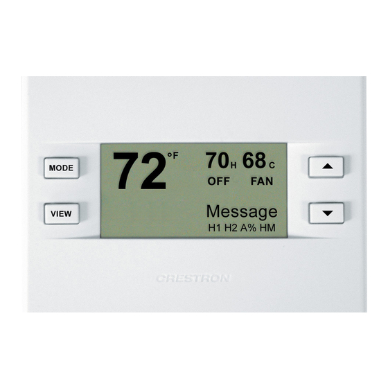
Fan Mode MODE AUTO VIEW 22 • Thermostats: CHV-TSTAT and CHV-THSTAT Crestron CHV-TSTAT and CHV-THSTAT The Main Screen displays the Current Temperature, System Mode, Fan Mode, and Set Point temperatures. The CHV-THSTAT also displays Relative Humidity and Humidifier Mode. Press the up ▲arrow button to increase the set point temperature. -
Page 27: View Button
Pressing the MODE button again displays the Crestron System screen. Use the up ▲and down▼arrow buttons to select ONLINE or HOLD. ONLINE – Data flows both ways, to and from the thermostat, enabling adjustment from a remote location. HOLD – Data flows one way, from the thermostat, blocking system commands to change the temperature and humidity when you do not want the current settings reset. - Page 28 Refer to “SCREEN OPTIONS” on page 18. NOTE: This is only a display and not for system activation. This display can be shown on either the CHV-TSTAT or the CHV-THSTAT. 3. MESSAGES Press the VIEW button again to display the “Messages” screen. This screen allows the user to view any text messages sent from the control system (Only when part of a Cresnet system).
-
Page 29: Programming Software
Crestron’s True Blue Support, log in at http://support.crestron.com. First-time users will need to establish a user account. The CHV-TSTAT and CHV-THSTAT thermostats do not require programming when used as stand alone devices. Programming as part of a Cresnet system allows additional functionality, including: Global Update and Global Page display –... -
Page 30: Programming With Crestron D3 Pro
PRO2 System View The System Views lower pane displays the PRO2 system tree. This tree can be expanded to display and configure the communications ports. Expanded PRO2 System Tree 26 • Thermostats: CHV-TSTAT and CHV-THSTAT Crestron CHV-TSTAT and CHV-THSTAT ® environment. -
Page 31: C2Net-Device Slot In Configuration Manager
Crestron CHV-TSTAT and CHV-THSTAT C2Net-Device Slot in Configuration Manager To incorporate a CHV-THSTAT or CHV-TSTAT into the system, drag one of the symbols for the thermostat from the Crestron Sensing Modules folder of the Device Library and drop it on C2-NET Device slot in System Views. The PRO2 system tree displays the thermostat symbol in Slot 9, with a default NET ID of 2A as shown in the example graphic below. - Page 32 Programming Manager (firmware version 1.1 or lower only). Refer to page 32 for a detailed description of the inputs and outputs Detail View of the Basic CHV-THSTAT and CHV-TSTAT Symbol Digital Inputs/Outputs Detail View of the Basic CHV-THSTAT and CHV-TSTAT Symbol Analog Inputs/Outputs 28 •...
- Page 33 Global Page display, Function pages, and System Messaging. Refer to page 32 for a detailed description of the inputs and outputs (firmware version 1.1 or lower only). Detail View of the Advanced CHV-THSTAT and CHV-TSTAT Symbol Digital Inputs/Outputs Operations and Installation Guide – DOC. 8163B Thermostats Thermostats: CHV-TSTAT and CHV-THSTAT •...
- Page 34 Thermostats 30 • Thermostats: CHV-TSTAT and CHV-THSTAT Crestron CHV-TSTAT and CHV-THSTAT Detail View of the Advanced CHV-THSTAT and CHV-TSTAT Symbol Digital Outputs Operations and Installation Guide – DOC. 8163B...
- Page 35 Crestron CHV-TSTAT and CHV-THSTAT Thermostats Detail View of the Advanced CHV-THSTAT and CHV-TSTAT Symbol Analog Inputs/Outputs Detail View of the Advanced CHV-THSTAT and CHV-TSTAT Symbol Serial Inputs Thermostats: CHV-TSTAT and CHV-THSTAT • 31 Operations and Installation Guide – DOC. 8163B...
- Page 36 Thermostat Symbol Definitions The following tables contain a detailed description of the inputs and outputs for the basic and advanced CHV-TSTAT and CHV-THSTAT symbols (firmware version 1.1 or lower only). NOTE: For the simplest possible programming, connect an appropriate analog signal to SETPOINT_1, and possibly SETPOINT_2.
- Page 37 Importing the value this way is required only if setup was a TSTAT with non-humidity remotes (no way of measuring indoor humidity) The network input value is overridden by a measured value if one is available Thermostats: CHV-TSTAT and CHV-THSTAT • 33 Thermostats...
- Page 38 "use" in set-up. This output is only active when a thermostat setup has humidity sensing capability, either by being a CHV-THSTAT or a CHV-TSTAT with humidity remote (Analog) Output Humidity value of built-in sensor (Analog) Output will send out the sensor values even if the sensor is declared, "omit"...
- Page 39 -6 - +6 degrees Symbol Definition Advanced Output Asserted when the system is heat/cool type (as opposed to heat pump) Advanced Output Asserted when system type is heat pump Thermostats: CHV-TSTAT and CHV-THSTAT • 35 Thermostats...
- Page 40 R1_T_OUTDOOR_F Advanced R2_T_OUTDOOR_F Advanced USE_LOC_HUM_F Advanced USE_R1_HUM_F Advanced 36 • Thermostats: CHV-TSTAT and CHV-THSTAT Crestron CHV-TSTAT and CHV-THSTAT Symbol Definition Advanced Output Asserted when dual-fuel heat pump system declared, In conventional heat pump systems, aux heat may be used to supplement heat pump heat. In dual-fuel setups, the aux heat output runs in place of the heat pump in cold weather.
-
Page 41: Example Programs
In Viewport, the thermostats output a string of characters that describe the setup and configuration of the thermostat. Refer to the following table for an explanation of this string. Each element of the setup string is separated by a period. The following are two examples of ID strings: CHV-THSTAT [v1.0] (HP.H2.C2.HA3.CA3.ADB2.H,Abp0,90.AX.F.L5.OS0.DA.UUDDUU) -
Page 42: Problem Solving
Crestron customer service representative. CHV-TSTAT/CHV-THSTAT Troubleshooting *H1, H2, C1, C2 may appear but the system will not activate until the 5 minute timer guards 38 • Thermostats: CHV-TSTAT and CHV-THSTAT Crestron CHV-TSTAT and CHV-THSTAT TROUBLE... -
Page 43: Further Inquiries
2.0 is not backward compatible with firmware release 1.1 and earlier. Upgrading from 1.1 to 2.0 will require complete reprogramming of the thermostat. In addition, version 2.0 is only compatible with 2-Series control processors. Refer to Doc. 8163C for complete descriptions and procedures concerning firmware version 2.0. -
Page 44: Appendix A: Glossary
BTU - British Thermal Unit – In scientific terms, it represents the amount of Call – A call is when the thermostat requests the heating or cooling system to turn Damper – Found in ductwork, this movable plate opens and closes to control Dead Band –... -
Page 45: Appendix B: About Heat Pumps
This is the heat pump balance point. In a dual-fuel system, the heat pump is supplemented with a standard furnace, which takes over when it becomes more efficient than the heat pump at very low temperatures. Operations and Installation Guide – DOC. 8163B Thermostats Thermostats: CHV-TSTAT and CHV-THSTAT • 41... -
Page 46: Return And Warranty Policies
All brand names, product names, and trademarks are the sole property of their respective owners. Windows is a registered trademark of Microsoft Corporation. Windows95/98/Me/XP and WindowsNT/2000 are trademarks of Microsoft Corporation. 42 • Thermostats: CHV-TSTAT and CHV-THSTAT Crestron CHV-TSTAT and CHV-THSTAT Operations and Installation Guide – DOC. 8163B... - Page 47 Crestron CHV-TSTAT and CHV-THSTAT Thermostats This page intentionally left blank. Thermostats: CHV-TSTAT and CHV-THSTAT • 43 Operations and Installation Guide – DOC. 8163B...
- Page 48 Crestron Electronics, Inc. Operations and Installation Guide – DOC. 8163B 15 Volvo Drive Rockleigh, NJ 07647 03.04 Tel: 888.CRESTRON Fax: 201.767.7576 Specifications subject to www.crestron.com change without notice.
Need help?
Do you have a question about the CHV-TSTAT and is the answer not in the manual?
Questions and answers