Crestron CHV-TSTAT Operation And Installation Manual
Hide thumbs
Also See for CHV-TSTAT:
- Operation and installation manual (48 pages) ,
- Dimension manual (38 pages) ,
- Quick start manual (4 pages)
Table of Contents
Advertisement
Quick Links
Advertisement
Table of Contents

Related Manuals for Crestron CHV-TSTAT


Summary of Contents for Crestron CHV-TSTAT
- Page 1 Crestron CHV-TSTAT & CHV-THSTAT Thermostats Operations and Installation Guide...
- Page 2 This document was prepared and written by the Technical Documentation department at: Crestron Electronics, Inc. 15 Volvo Drive Rockleigh, NJ 07647 1-888-CRESTRON All brand names, product names and trademarks are the property of their respective owners. ©2002 Crestron Electronics, Inc.
-
Page 3: Table Of Contents
Wiring Diagrams ......................8 Installation ......................... 12 Thermostat Setup....................... 14 Operating the Thermostat ..................18 Programming Software ......................20 Programming with the Crestron D3 Pro ..............21 Programming with SIMPL Windows ................ 21 Problem Solving ........................32 Troubleshooting......................32 Further Inquiries ......................33 Firmware Upgrades .................... -
Page 4: Quick Installation Reference
Thermostats Crestron CHV-TSTAT and CHV-THSTAT Quick Installation Reference 1. Select a suitable location and run the connecting wires from the heating/cooling system and the Cresnet system. Refer to page 5 for a description of the thermostat connectors. Refer to page 7 for Network wiring details. -
Page 5: Thermostats: Chv-Tstat And Chv-Thstat
Functions and Features The CHV-TSTAT and CHV-THSTAT series are wall-mounted universal thermostats that can be part of a Crestron Home™ total control system. The thermostats are capable of controlling one or two-stage heating and cooling systems. Each thermostat is available in three colors: almond, black and white. The suffix ‘A’, ‘B’, and ‘W’, respectively denotes color, i.e., CHV-TSTATB is a black unit. -
Page 6: Remote Sensors
Subsequent firmware releases will support the addition of up to four optional remote sensors, in any combination, for each thermostat. NOTE: The CHV-TSTAT and CHV-THSTAT allow the user to set a temperature that the heating and/or cooling system maintains. This is called the “Set Point”. Refer to “Operating the Thermostat”... -
Page 7: Specifications
Depth: 1.04 in (2.63 cm) Weight: 5.80 oz (165 g) The latest versions can be obtained from the Downloads | Software Updates section of the Crestron website (www.crestron.com). Refer to NOTE after last footnote. Crestron 2-Series control systems include the AV2, CP2, CP2E, MP2, MP2E, PAC2, PRO2, and RACK2. -
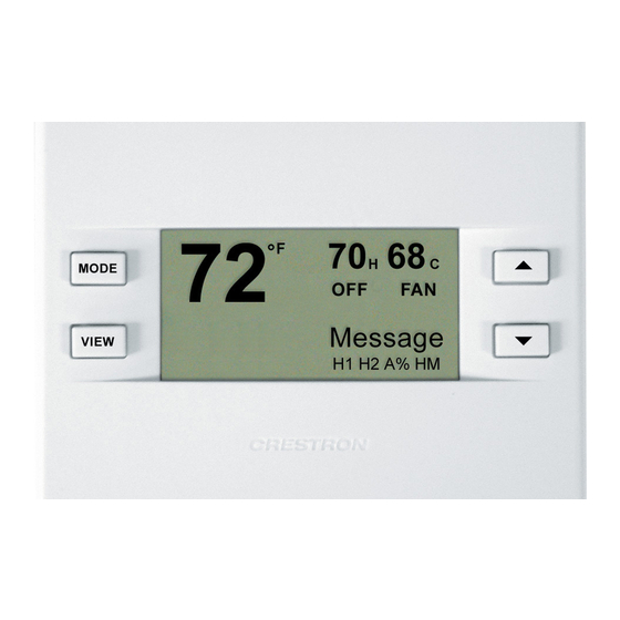
Page 8: Physical Description
Crestron CHV-TSTAT and CHV-THSTAT Physical Description Refer to the illustrations below and on next page. The CHV-TSTAT and CHV- THSTAT are enclosed in a plastic enclosure with four buttons and an LCD display on the front. The back of the unit has ventilation slots, and holes for mounting the unit and wiring. - Page 9 Connection View (Backplate, view from the front with cover removed) NETWORK Ports The CHV-TSTAT and CHV-THSTAT have four types of connections on the inside back plate (refer to graphic above). NET (Optional) – provides communication to the control system and Cresnet power to the CHV-TSTAT and CHV-THSTAT.
-
Page 10: Industry Compliance
Buttons There are four buttons used to setup and adjust the thermostat. MODE – Access to the user controls (System Mode, Fan Mode, Humidifier, Crestron System, and Global Update) VIEW – Access to Humidity reading, Outdoor Temperature reading, and System Messages. -
Page 11: Setup
If the unit is a home-run from a Crestron system power supply network port, the power factor of that unit is the power factor of the entire run. The length of the run in feet and the power factor of the run should be used in the following resistance equation to calculate the value on the right side of the equation. -
Page 12: Wiring Diagrams
Thermostats Crestron CHV-TSTAT and CHV-THSTAT Wiring Diagrams The wiring diagrams that follow show power wiring connections for the CHV-TSTAT and CHV-THSTAT. Choose one of the following methods. Power Connections (Note the P4 Jumper Position on Circuit Board) Heating System Powered... -
Page 13: System Connections
NOTE: For the power supply, provide disconnect means and overload protection as required. NOTE: Use either connector O or B for changeover control. Two-wire Heat Only Backplate NETWORK Heating relay or valve coil 24 VAC 120 VAC Thermostats: CHV-TSTAT and CHV-THSTAT • 9 Operations and Installation Guide - DOC. 8163... - Page 14 Backplate NETWORK Jumper between RH and RC Heat System Transformer Heat Relay 24 VAC 120 VAC Cooling System Compressor Relay Transformer Fan Relay 24 VAC 120 VAC 10 • Thermostats: CHV-TSTAT and CHV-THSTAT Operations and Installation Guide – DOC. 8163...
- Page 15 Aux Heat Transformer Aux Heat Relay 24 VAC 120 VAC Changeover Valve Second Stage Compressor First Stage Compressor Heat Pump System Fan Relay Transformer 120 VAC 24 VAC Thermostats: CHV-TSTAT and CHV-THSTAT • 11 Operations and Installation Guide - DOC. 8163...
-
Page 16: Installation
(make sure front plate snaps in place and no wires are pinched). NOTE: If replacing an existing thermostat, make note of the wire colors and positions before removing the old thermostat. 12 • Thermostats: CHV-TSTAT and CHV-THSTAT Operations and Installation Guide – DOC. 8163... - Page 17 Stud Single-gang electrical box Panhead (not provided) 6/32 x 1 in Installation view – Direct mount to wall Wall Anchors (not provided) Backplate Mounting Screws (not provided) Thermostats: CHV-TSTAT and CHV-THSTAT • 13 Operations and Installation Guide - DOC. 8163...
-
Page 18: Thermostat Setup
(requires outdoor sensor) AUX Balance Point (Heat Pump with Aux only) Maximum outdoor temperature at which Aux Heat System supplements the heat pump (requires outdoor sensor) 14 • Thermostats: CHV-TSTAT and CHV-THSTAT Operations and Installation Guide – DOC. 8163... - Page 19 SIMPL Windows SETUP: DEVICE OPTS MODE Network ID: Select LCD Screen Contrast LCD Contrast (1 Lighter through 10 Darker) VIEW Firmware Version [0.1] Bld 133 CRESTRON Thermostats: CHV-TSTAT and CHV-THSTAT • 15 Operations and Installation Guide - DOC. 8163...
-
Page 20: Display Options
(for example: lights, alarms, etc.). Each of the two pages has two definable buttons. The up ▲and down ▼ keys are set by indirect text for each page, refer to “CHV-TSTAT and CHV-THSTAT Advanced Symbol” on page 24. Display Global Page? - Page 21 Press MODE button to return to the first screen. Simultaneously press and hold the MODE and VIEW buttons to return to normal operation mode. NOTE: Thermostat will not leave the setup mode until a valid sensor selection is made. Thermostats: CHV-TSTAT and CHV-THSTAT • 17 Operations and Installation Guide - DOC. 8163...
-
Page 22: Operating The Thermostat
C2 – Stage 2 Cooling System System Mode It may also be necessary to access a series of screens. Pressing MODE button allows the user to access System Mode, Fan Mode, Crestron System On/Offline, and Global Update mode. The “System Mode” screen appears System Mode MODE when the MODE button is initially pressed once. - Page 23 (i.e., lighting control, alarm system, etc.). Press the MODE button to clear (CLR) the message(s). Acknowledges to the control system that the message has been read. Thermostats: CHV-TSTAT and CHV-THSTAT • 19 Operations and Installation Guide - DOC. 8163...
-
Page 24: Programming Software
Inquiries" on page 33. System Messaging – Allows the control system to send text messages to the thermostat. NOTE: As of press time, Crestron D3 Pro does not yet support the thermostats. Version numbers and release dates to be announced. ... -
Page 25: Programming With The Crestron D3 Pro
Thermostats Programming with the Crestron D3 Pro The easiest method of NOTE: As of press time, Crestron D3 Pro does not yet support the thermostats. programming, but does not Version numbers and release dates to be announced. offer as much flexibility as SIMPL Windows. - Page 26 Expanded PRO2 System Tree C2Net-Device Slot in Configuration Manager To incorporate a CHV-THSTAT or CHV-TSTAT into the system, drag one of the symbols for the thermostat from the Crestron Sensing Modules folder of the Device Library and drop it on C2-NET Device slot in System Views. The PRO2 system tree displays the thermostat symbol in Slot 9, with a default NET ID of 2A as shown in the example graphic below.
- Page 27 The advanced symbol allows a broader range of functions, including the ability to control other devices (lighting, alarms, etc.), interact with other thermostats, receive messages from the Crestron system, import and export temperature and humidity information. The basic symbol, while simpler, still provides all the necessary connections to operate and control a Heating Ventilation and Air Conditioning (HVAC) system.
- Page 28 Thermostats Crestron CHV-TSTAT and CHV-THSTAT Detail View of the Basic CHV-THSTAT and CHV-TSTAT Symbol Analog Inputs/Outputs CHV-THSTAT AND CHV-TSTAT ADVANCED SYMBOL The advanced symbol allows additional functionality, including: Global Update and Global Page display, Function pages, and System Messaging. Refer to page 27 for a detailed description of the inputs and outputs.
- Page 29 Crestron CHV-TSTAT and CHV-THSTAT Thermostats Detail View of the Advanced CHV-THSTAT and CHV-TSTAT Symbol Digital Outputs Thermostats: CHV-TSTAT and CHV-THSTAT • 25 Operations and Installation Guide - DOC. 8163...
- Page 30 Thermostats Crestron CHV-TSTAT and CHV-THSTAT Detail View of the Advanced CHV-THSTAT and CHV-TSTAT Symbol Analog Inputs/Outputs Detail View of the Advanced CHV-THSTAT and CHV-TSTAT Symbol Serial Inputs 26 • Thermostats: CHV-TSTAT and CHV-THSTAT Operations and Installation Guide – DOC. 8163...
- Page 31 Crestron CHV-TSTAT and CHV-THSTAT Thermostats Thermostat Symbol Definitions The following tables contain a detailed description of the inputs and outputs for the basic and advanced CHV-TSTAT and CHV-THSTAT symbols. System Mode Related Digital Joins Signal Name Symbol* Definition SYS_MODE_OFF Both...
- Page 32 TSTAT with non-humidity remotes (no way of measuring indoor humidity) The network input value is overridden by a measured value if one is available 28 • Thermostats: CHV-TSTAT and CHV-THSTAT Operations and Installation Guide – DOC. 8163...
- Page 33 The "regulation" humidity that a thermostat is using, This is the average of the humidity sensor inputs declared "use" in set-up This output is only active when a thermostat setup has humidity sensing capability, either by being a CHV-THSTAT or a CHV-TSTAT with humidity remote (Analog) BUILT_IN_HUMID_F Advanced...
- Page 34 Definition HEAT_COOL SYS_F Advanced Output Asserted when the system is heat/cool type (as opposed to heat pump) HEATPUMP_SYS_F Advanced Output Asserted when system type is heat pump 30 • Thermostats: CHV-TSTAT and CHV-THSTAT Operations and Installation Guide – DOC. 8163...
- Page 35 Asserted when using built in humidity sensor (THSTAT) USE_R1_HUM_F Advanced Output Asserted when using remote 1 humidity sensor USE_R2_HUM_F Advanced Output Asserted when using remote 2 humidity sensor Thermostats: CHV-TSTAT and CHV-THSTAT • 31 Operations and Installation Guide - DOC. 8163...
-
Page 36: Problem Solving
Output Asserted when remote 2 humidity sensor is outdoor Problem Solving Troubleshooting The table below provides corrective action for possible trouble situations. If further assistance is required, please contact a Crestron customer service representative. CHV-TSTAT/CHV-THSTAT Troubleshooting TROUBLE POSSIBLE CORRECTIVE ACTION... -
Page 37: Further Inquiries
Therefore, please check Crestron’s website (http://www.crestron.com/downloads/software_updates.asp) for the latest version of firmware. Not every product has a firmware upgrade, but as Crestron improves functions, adds new features, and extends the capabilities of its products, firmware upgrades are posted. If you have questions regarding upgrades procedures, contact Crestron customer service. -
Page 38: Appendix A: Glossary
68% of its capacity. When the temperature outside goes very low or very high, the system adjusts to full capacity (second stage) to meet the demand. 34 • Thermostats: CHV-TSTAT and CHV-THSTAT Operations and Installation Guide – DOC. 8163... -
Page 39: Appendix B: About Heat Pumps
This is the heat pump balance point. In a dual-fuel system, the heat pump is supplemented with a standard furnace, which takes over when it becomes more efficient than the heat pump at very low temperatures. Thermostats: CHV-TSTAT and CHV-THSTAT • 35 Operations and Installation Guide - DOC. 8163... -
Page 40: Return And Warranty Policies
CRESTRON shall not be liable to honor the terms of this warranty if the product has been used in any application other than that for which it was intended, or if it has been subjected to misuse, accidental damage, modification, or improper installation procedures. - Page 41 Crestron CHV-TSTAT and CHV-THSTAT Thermostats This page intentionally left blank. Thermostats: CHV-TSTAT and CHV-THSTAT • 37 Operations and Installation Guide - DOC. 8163...
- Page 42 Thermostats Crestron CHV-TSTAT and CHV-THSTAT This page intentionally left blank. 38 • Thermostats: CHV-TSTAT and CHV-THSTAT Operations and Installation Guide – DOC. 8163...
- Page 43 Crestron CHV-TSTAT and CHV-THSTAT Thermostats This page intentionally left blank. Thermostats: CHV-TSTAT and CHV-THSTAT • 39 Operations and Installation Guide - DOC. 8163...
- Page 44 Crestron Electronics, Inc. Operations and Installation Guide – DOC. 8163 15 Volvo Drive Rockleigh, NJ 07647 12.02 Tel: 888.CRESTRON Fax: 201.767.7576 Specifications subject to www.crestron.com change without notice.
Need help?
Do you have a question about the CHV-TSTAT and is the answer not in the manual?
Questions and answers