Crestron CHV-THSTAT Quick Start Manual
Heating/cooling and humidity thermostat
Hide thumbs
Also See for CHV-THSTAT:
- Operation and installation manual (100 pages) ,
- Dimension manual (38 pages) ,
- Operation and installation manual (48 pages)
Advertisement
Crestron Thermostat
Step 1
Thermostat Mounting
Mounting
Screws
(not provided)
Step 2
Thermostat System Connections
Thermostat Quick Start Guide – Doc. 6145A
Crestron Quick Start Thermostat
CHV-TSTAT and CHV-THSTAT Series
For Additional details, refer to the latest version of
the Operations and Installation Guide, Doc. 8163
Wall Anchors
(not provided)
Backplate
HUM - Energized (connected) to RHU during humidity call
RHU - Reference for humidifier
RSR - Remote Sensor Returns - Common sensor terminal
RS1 - Remote Sensor terminal - Connect the sensor from RS1 to RSR
RS2 - Remote Sensor terminal - Connect the sensor from RS2 to RSR
24(C) - 24 VAC common terminal supplies remote 24 VAC power
to thermostat
24(R) - 24 VAC reference terminal. Can be connected to RH or RC
by P4 jumper setting (refer to following page), or tied directly
to power source
TOP
W2 - Heat (stage two), energized (connected) to RH during a call for
second stage heat in heat/cool systems
W/W1 - Heat (single stage)/heat (stage one) energized
to RH during a call for heat in heat/cool systems or aux heat
in heat pump systems
B - Energized to RC during non-cooling modes
O - Changeover control, energized to RC during cooling modes
Y2 - Compressor (stage two), energized to RC on two-stage
systems on call for second stage
Y/Y1 - Compressor (stage one), energized to RC when
compressor (or first stage) is run
G - Fan, energized to RC during call for fan
RC - Reference Cool, used for calls to cooling system
RH - Reference Heat, used for calls to heating system
Panhead
6/32 x 1 in
Network Connection
for Crestron
Installer Only
NETWORK
Backplate
CHV-TSAT and CHV-THSTAT Series •
Quick Start Guide
Stud
Single-gang
electrical box
(not provided)
Backplate
NOTE:
Fill the Electrical Box
with Thermal
Insulation Material
1
Advertisement
Table of Contents

Subscribe to Our Youtube Channel
Related Manuals for Crestron CHV-THSTAT


Summary of Contents for Crestron CHV-THSTAT
-
Page 1: Quick Start Guide
RC - Reference Cool, used for calls to cooling system RH - Reference Heat, used for calls to heating system Quick Start Guide Stud Single-gang electrical box (not provided) Backplate Panhead 6/32 x 1 in NOTE: Fill the Electrical Box with Thermal Insulation Material CHV-TSAT and CHV-THSTAT Series •... - Page 2 NOTE: Ensure that the power circuits are shut off at the source before connecting the thermostat. Provide disconnect means and overload protection as required for the power supply. • CHV-TSTAT and CHV-THSTAT Series Thermostat Quick Start Guide – Doc. 6145A...
- Page 3 Crestron Thermostat Quick Start Guide CHV-TSAT and CHV-THSTAT Series • 3 Thermostat Quick Start Guide – Doc. 6145A...
-
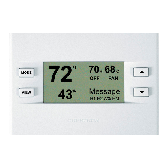
Page 4: Thermostat Operation
Point level View the outdoor temperature (if an outdoor Outdoor sensor has been installed) and outdoor humidity (if available) Crestron Electronics, Inc. 15 Volvo Drive Rockleigh, NJ 07647 Tel: 888.CRESTRON Fax: 201.767.7576 www.crestron.com Main Screen MODE HEATING HEAT ONLY NET FAULT...
Need help?
Do you have a question about the CHV-THSTAT and is the answer not in the manual?
Questions and answers