Sign In
Upload
Manuals
Brands
Eurotech Manuals
Gateway
ReliaGATE 10-12-6 Series
Eurotech ReliaGATE 10-12-6 Series Manuals
Manuals and User Guides for Eurotech ReliaGATE 10-12-6 Series. We have
1
Eurotech ReliaGATE 10-12-6 Series manual available for free PDF download: User Manual
Eurotech ReliaGATE 10-12-6 Series User Manual (118 pages)
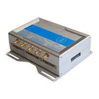
IoT Edge Gateway TI AM335x, LTE Cat 1
Brand:
Eurotech
| Category:
Gateway
| Size: 2.92 MB
Table of Contents
Trademarks
2
Intended Audience of this Document
2
Revision History
2
Usb 0, Usb 1, Usb
2
How to Get Started
3
Table of Contents
5
Contents
5
1 Safety Instructions
9
Warning Messages
9
Warning Messages for Harm to Persons
9
Caution: Wireless Safety
10
Warning Messages for Damage to Property
10
Warning: Power Supply Safety
10
Warning: Battery Safety
11
2 Consignes de Securite
13
Messages D'avertissement
13
Messages D'avertissement Relatifs au Dommage aux Personnes
13
Attention: Sécurité Sur la Connectivité Sans Fil
14
Avertissement: Sécurité de L'alimentation Électrique
14
Messages D'avertissement Relatifs aux Dommages Matériels
14
Avertissement: Sécurité de la Batterie
15
3 How to Receive Technical Assistance
17
How to Ask for Technical Support
17
How to Send a Product for Repair
17
4 Comment Obtenir une Assistance Technique
19
Comment Contacter le Support Technique
19
Comment Retourner un Produit en Service après Vente
19
5 Conventions Used
21
Conventions for Signal Names
21
Conventions for Signal Types
21
6 Product Overview
23
Product Description
23
Intended Use and Not Allowed Uses of the Product
24
Intended Use
24
Not Allowed Uses
24
Technical Specifications
25
Optional Accessories
27
Product Labels
29
7 Regulatory Information
31
CE Marking
31
Packaging and Packaging Waste
31
Product Disposal and Recycling
31
Safety
31
WEEE Compliance
31
Directive RED 2014/53/EU
32
Rohs 3 Compliance
32
Statement for Class a Equipment (Vers.: -61)
33
Statement for KN 32/35 (Vers.: -61)
33
FCC Class B Digital Device Notice
34
FCC Marking
34
FCC/ISED Regulatory Notices
34
FCC Restrictions on 5 Ghz Wi-Fi Usage
35
ISED Canada Regulatory Notices
36
ISED Class B Digital Device Notice
36
Responsible Parties: Canadian Representative Contact Information
36
Antennas List
37
Labeling Information
37
RF Radiation Exposure Statement
37
REACH Compliance
38
8 Interfaces Overview
39
Front Side Interfaces Overview
39
Rear Side Interfaces Overview
40
Service Panel Interfaces
41
Right Side Interface Overview
42
Left Side Interface Overview
43
LED Indicators Overview
44
9 Interfaces in Detail
45
Wi-Fi and Bluetooth (All Vers. Except: -61, -63, -64)
45
Wi-Fi Specifications
45
Antennas Connectors Specifications
46
BLE Specifications
46
Bluetooth Specifications
46
Internal Cellular Modem (All Vers. Except: -61, -62)
47
Internal Cellular Modem Specifications (According to Product Versions)
47
LTE - Single Antenna Operation Notes
47
Antennas Connectors Specifications
50
The Microsim Card Holders
51
Antenna Connector Specifications
53
Internal GNSS (Vers.: -65G, -66G, -67G)
53
Internal GNSS Specifications
53
Digital I/Os
54
Insulated Digital Inputs
54
Digital I/Os Connector Specifications
55
Insulated Digital Outputs
55
COM 0 and COM 1
56
Note for Fail-Safe Resistors for COM 0 in RS-485 Mode
56
Note for Termination Resistors for COM 0 in RS-485 Mode
56
Note for Termination Resistors for COM 1 in RS-485 Mode
56
Note for Fail-Safe Resistors for COM 1 in RS-485 Mode
57
Note for RS-485 Half Duplex (Only for COM 0 in RS-485 Mode)
57
COM 0 and COM 1 Connector Specifications
58
CAN 0 and CAN
59
CAN 0 and CAN 1 Connector Specifications
59
ETH 0 and ETH
60
ETH 0 and ETH 1 Connectors Specifications
60
Ethernet Specifications
60
USB 0 and USB 1 Connectors Specifications
61
USB 2 Connector Specifications
61
Expansion Connector
62
Expansion Connector Specifications
62
TTL Serial Console
63
TTL Serial Console Connector Specifications
63
How to Insert / Remove the Microsd Card in the Holder
64
Microsd Card Holder
64
RTC (Real Time Clock)
65
The RTC Backup Battery
65
The RTC Device "/Dev/Rtc1
65
Accelerometer and Gyroscope
66
Programmable Pushbutton
66
Watchdog
66
10 The Software
67
The Linux os Distribution
67
The Bootloader Procedure
67
How to Create and Use a Bootable Microsd Card for a Linux Release
67
Ensure Power Supply During Installation and Update
67
The TPM
68
11 How to Login the Administration Console
69
Default Credentials
69
How to Login Using the Serial Console
69
How to Login Via Secure Shell (SSH)
69
How to Change the Password
70
How to Login Via Eth0
70
How to Login Via Eth1
70
12 How to Manage Interfaces in Linux
71
How to Drive the Gpios: the GPIO Utility
71
How to Determine the Version of Linux Installed
72
How the Storage Memory Is Exposed
72
How to Manage Wi-Fi and Bluetooth
72
How to Manage the Internal Cellular Modem
73
How to Select the Microsim Card Holder to Use
73
Note for LE910-NA1 Modem: AT&T / Verizon Firmware Support
73
How to Disable/Enable the Diversity (CELL DIV) Function
74
How to Manage the Internal GNSS
75
How the TTL Serial Console Is Exposed
76
How to Enable the CAN Bus 5V
76
How to Manage the CAN Ports
76
How to Send/Receive a Message Via a CAN Port
76
How to Setup a CAN Port
76
How to Manage the COM Ports
77
How to Set the RS-422/485 Modes for COM 0
77
How to Set the Termination Resistors for COM 0 in RS-485 Mode
77
How to Set the RS-232/485 Modes for COM 1
81
How to Test a Serial Port
84
12.10 How to Manage the Digital I/Os
85
12.11 How to Manage the LED Indicators
85
12.12 How the Ethernet Ports Are Exposed
85
How to Enable the 3.3V and 5V Power Supply on the Expansion Connector
86
12.14 How the RTC Is Exposed
87
12.15 How the Watchdog Is Exposed
88
For more Information
88
How to Manage the Watchdog from the Command Line
88
How to Manage the Watchdog Using the C Programming Language
88
12.16 How to Output Accelerometer and Gyroscope Values
89
12.17 How to Read the Internal Temperature Sensor
90
12.18 How to Know the Programmable Pushbutton Status
90
12.19 the TPM and the Tpm2-Tools Package
90
12.20 Optional: How to Manage the Reliacell Power Supply
90
13 How to Compile Custom Software
91
How to Setup the Toolchain
91
How to Use the Toolchain to Compile Custom Software
91
14 Eurotech Everyware Iot
93
Everyware Software Framework (ESF)
93
The ESF Web UI
94
The ESF Wires Application
95
Everyware Cloud (EC)
96
For more Information
96
15 Mechanical Specifications
97
Product Mechanical Dimensions
97
Mounting Bracket Mechanical Dimensions
98
16 How to Install the Product
99
How to Install the Product Using the Mounting Bracket
99
How to Replace the Mounting Bracket with the DIN Rail Mounting Clip or Vice Versa
100
How to Replace the Mounting Bracket with the DIN Rail Mounting Clip
100
How to Replace the DIN Rail Mounting Clip with the Mounting Bracket
101
Which Screws Are Used with the Mounting Bracket or with the DIN Rail Mounting Clip
102
How to Install the Product on a DIN Rail
103
How to Install/ Remove the Product On/ from a DIN Rail
103
How to Remove the Product from a DIN Rail
103
17 Power Supply. How to Turn ON/OFF and Reset the Product
105
Power Supply Specifications
105
Power in Connector Specifications
105
How to Supply Power and Turn on the Product
106
How to Turn off the Product
107
How to Reduce the Power Consumption of the Product
107
How to Hardware Reset the Product
107
18 How to Maintain the Product
109
How to Safely Remove the Power Supply
109
How to Verify the Installation of the Product
109
How to Clean the Product
109
Appendix 1: Advanced Boot Options
111
Advanced Boot Options Availability
111
How to Configure a Boot Option
111
How to Gain Access to the Bootloader CLI
111
How to Change the Default Boot Option
112
The Production Fitimage
112
How to Define the Variants
112
How to Manually Configure the System to Boot from a Different DTB Within the Current Fitimage
112
Appendix 2: Expansion Connector Pin Map with Respect to Device Tree Pin Assignment
115
Notes
117
Advertisement
Advertisement
Related Products
Eurotech DynaGate 10-12 Series
Eurotech DynaGate 10-12-X1
Eurotech DynaGate 10-12-X2
Eurotech DynaGate 10-12-X5
Eurotech DynaGate 10-12-X4
Eurotech DynaGate 10-12-X6
Eurotech DynaGate 10-12-X3
Eurotech DynaGate 10-12-X7
Eurotech ReliaGATE 10-14-32
Eurotech ReliaGATE 10-14 Series
Eurotech Categories
Gateway
Motherboard
Indoor Furnishing
Microcontrollers
Dryer
More Eurotech Manuals
Login
Sign In
OR
Sign in with Facebook
Sign in with Google
Upload manual
Upload from disk
Upload from URL