Table of Contents
Advertisement
Quick Links
Advertisement
Table of Contents

Subscribe to Our Youtube Channel
Related Manuals for Festo CPX-CEC Series


Summary of Contents for Festo CPX-CEC Series
- Page 1 CPX-CEC-...
-
Page 2: Table Of Contents
1.10.1 I/O update ........................52 1.10.2 Using CANopen masters ....................52 1.10.3 CPX-MMI use and program downloads ................52 1.11 Appendix ............................ 53 1.11.1 Festo terms and conditions for the use of software packages ........53 Glossary ............................55 Index ..............................57... -
Page 3: Cpx-Cec
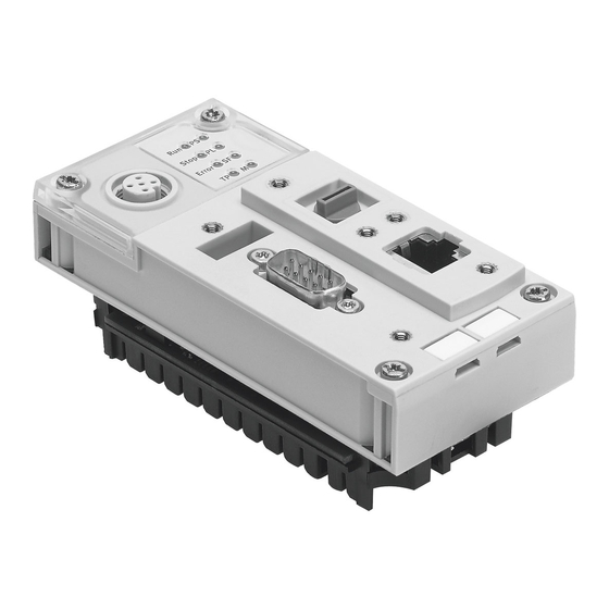
1 CPX-CEC-... Modular valve terminal with integrated controller CPX-CEC-... You can find a complete description of the Festo CoDeSys controller CPX-CEC-... in the manual P.BE- CPX-CEC-EN (see also CPX-CEC_en.pdf on CD-ROM). A complete development environment based on CoDeSys 2.3.x from the company 3S - Smart Software Solutions GmbH exists for the Festo CoDeSys controller CPX-CEC-.. -
Page 4: Additional Functions For Cpx-Cec
CPX-CEC-... 1.2.2 Additional functions for CPX-CEC-... CoDeSys provided by Festo offers the following additional functions that have been specially adapted to the CPX-CEC-...: Additional function Brief description Libraries for the Festo CoDeSys System libraries that provide access to the special hardware –... -
Page 5: Designated Use
1.2.4 Designated use With CoDeSys provided by Festo, the user who is familiar with the component connected to the PC can undertake the configuration, commissioning and programming of the supported controllers. Observe the standards specified in the relevant sections, as well as national and local laws and technical regulations. - Page 6 CPX-CEC-... Further conventions [Project] [New] Menu items are framed in square brackets, for example the [New ...] command in the [Project] menu opens a new project. "OK" The names of windows, dialogues and buttons, e.g. "Message window," "Extract project," "OK" as well as designations are displayed in inverted commas. CTRL Names of keys on the PC keyboard are represented in the text with uppercase letters (e.g.
-
Page 7: Overview Of Functions And Libraries
Modular valve terminal with integrated controller CPX-CEC-... Overview of functions and libraries 1.3.1 Function overview This function overview specifies which functions are supported or not supported by the CPX-CEC-... and which defaults are applied when a new project for this target system is created. Functionality/functions Supported Project options... - Page 8 CPX-CEC-... Functionality/functions Supported Manage projects All functions Manage objects All functions General editing All functions functions Functionality/functions Supported General online Login functions (part 1) Logout Download Start Stop Reset Reset (cold) Reset (original) Toggle breakpoint Breakpoint dialog Step over Step in Single cycle Write values Force values...
- Page 9 Modular valve terminal with integrated controller CPX-CEC-... Functionality/functions Supported Window All functions Editors (languages) Instruction list (IL) Structured text (ST) Sequential function chart (SFC) Function block diagram (FBD) Ladder diagram (LD) Continuous function chart (CFC) Settings Automatic calculation of addresses Adjustable configuration Check for overlapping addresses...
- Page 10 CPX-CEC-... Functionality/functions Supported System events start stop before_reset after_reset shutdown excpt_cycletime_overflow excpt_watchdog excpt_divide_by_zero CPX_System_Fault CAN_error_passive CAN_bus_off Task configuration in All functions online mode Task processing The task with the valid condition is executed: this means after the time specified under "Interval" has expired or after a leading edge from the condition variable specified under Event.
- Page 11 Extras -> Read recipe Force values and write to watch manager Working area All functions Functionality/functions Supported/name Target settings Target Name Festo CPX-CEC/CPX-CEC-C1 Platform Festo CPX-CEC-M1 Parameter size adapted to type Only relevant for X86 Functionality/functions Setting Target settings Memory...
- Page 12 CPX-CEC-... Functionality/functions Supported Target settings General I/O configuration: Configurable I/O configuration: Download as file No (attached to program code) I/O configuration: No address check Yes/option of setting Support CANopen configuration Support preemptive multitasking Yes/fixed Online change Yes/option of setting Update unused I/Os Yes/option of setting Single task in multitasking...
- Page 13 Modular valve terminal with integrated controller CPX-CEC-... Functionality/functions Supported Target settings Network Support parameter manager Yes/option of setting functionality Support network variables /option of setting Names of supported network interfaces Index ranges for parameters Index ranges for variables Index ranges for mappings Subindex range Visualization Display width in pixel...
- Page 14 CPX-CEC-... Functionality/functions Supported Trace All functions PLC browser All functions Parameter manager All functions All functions IEC operators and Arithmetic operators additional functions Bit string operators that upgrade standards Bit shift operators Selection operators Comparison operators Address operators Call operator Type conversions Numerical operators Parameters in...
- Page 15 Tools for activating All functions external applications SoftMotion All functions 1) Not included in the scope of delivery of CoDeSys provided by Festo. 2) Only in the CPX-CEC-M1 variant with restrictions (see the chapter "Configuring SoftMotion for CPX- CEC-M1")
-
Page 16: Libraries
CPX-CEC-... 1.3.2 Libraries CoDeSys provided by Festo offers the following libraries for the Festo CoDeSys controller. Library Description Source Standard.lib Modules that the IEC61131-3 requires as standard modules for an IEC programming system. Standard – libraries for Util.lib Modules for BCD conversion, bit/byte functions,... - Page 17 If the library is not included in your library manager, you can add the library using the 'Additional library' dialog box. Only use libraries that are approved for the CPU module. A list of libraries approved for Festo CoDeSys controllers is included in the installation directory under ...\Targets\Festo\"Controller"\Library\..
-
Page 18: Preliminary Work
Documentation for OPC server V2.0, installation and use (English) Table: List of important user documentation After installing CoDeSys pb Festo, you will find further documentation in the program directory of CoDeSys provided by Festo on your PC: ...\CoDeSys V2.3\Documents ...\CoDeSys V2.3\Targets\Festo\"Controller"\Help Subfolders contain the documents in different languages. -
Page 19: Installing The Target System
1.4.3 Installing the target system If the software package "CoDeSys V2.3 provided by Festo" has already been installed and operated with other controllers, the Target Support Package (TSP) for the new target system may have to be installed. The Target Support Package contains information on the controllers (target system) required by "CoDeSys V2.3 provided by Festo". - Page 20 CPX-CEC-... Figure: Opening the Target Support Package • Select the file "CPX-CEC.tnf", for example, from the temporary folder that you created when unpacking the ZIP file. Then click "Open". The Target Support Package is added on the left side under "Possible Targets". Figure: Possible and installed target systems •...
- Page 21 Modular valve terminal with integrated controller CPX-CEC-... Figure: Target system is added to "Installed Targets" • Click the "Close" button to exit the program. The temporary folder that was created during the unpacking process can now be deleted together with all contents because it is no longer required.
-
Page 22: Selecting The Target System
Select the [File] [New] menu command. The "Target Settings" window is then opened. Figure: New project • Select the relevant entry to configure projects on the Festo CoDeSys controller. • Click "OK" to confirm this target system setting. The next window opens automatically so that you can create a new programming module. -
Page 23: Cpx-Cec
Modular valve terminal with integrated controller CPX-CEC-... CPX-CEC-... PLC configuration The PLC configuration includes a description of the target system settings. The description specifies which controller components are used and how they are configured. • Select the "Resources" tab in the Organizer object. Figure: Opening the PLC configuration •... -
Page 24: Ip Address Setting
CPX-CEC-... 1.5.1 IP address setting In the "Network Configuration" dialog, you can: search within the network, – add a connection to a controller, – modify network settings for the listed controllers, – set a controller as a so-called active PLC. –... - Page 25 IP address of the first Festo CoDeSys controller: 192.168.2.50 (default) – IP address of the second Festo CoDeSys controller: e.g. 192.168.2.51 (must be configured) – If the search for the CPX-CEC-... within the network is unsuccessful (e.g. if the device is located in a remote subnet e.g.
-
Page 26: Target System Settings
CPX-CEC-... 1.5.2 Target system settings The "Target Settings" dialog window is located in the "Object Organizer". • Activate the "Resources" tab and double-click on the relevant entry to open the "Target Settings" dialog window. Figure: Opening the target settings The name of the target system is located at the top of the dialog window (CPX-CEC-... in this case). The dialog window expands and displays all functions for setting the CPX-CEC-... -
Page 27: General Parameter Information
Modular valve terminal with integrated controller CPX-CEC-... "General" tab Figure: Target settings "General" tab "Load bootproject automatically" function Note The boot project in the controller can be overwritten automatically. • Deactivate the "Load bootproject automatically" function if necessary. "No address check" function Note The "No address check"... -
Page 28: System Parameter Settings
1.5.5 Rotary switch settings The complete description for the Festo CoDeSys controller CPX-CEC P.BE-..-... contains information on rotary switch settings for the CPX-CEC-... (see also CPX-CEC_en.pdf on CD-ROM). The rotary switch is permanently assigned to a variable in the PLC configuration. The marking in the configuration area makes this input address available as a global variable (%IB0, %IX0.0 to %IX0.7) so... -
Page 29: Manual I/O Configuration Of The Cpx System
You can define the setpoint configuration manually using the "PLC Configuration" of CoDeSys provided by Festo. After a new project is created for the CPX-CEC-..., a list of basic CPX-CEC-... modules appears in the configuration tree of the PLC configuration. - Page 30 CPX-CEC-... Addressing settings • Please read the instructions in the CoDeSys basic documentation relating to "Automatic calculation of addresses" and "Check for overlapping addresses". Figure: CPX-CEC settings Options for modifying the "base parameters" of a module: • Edit the addresses for the I, O and diagnosis specified automatically by CoDeSys. •...
- Page 31 Modular valve terminal with integrated controller CPX-CEC-... Configuring CANopen masters (CPX-CEC-C1 and CPX-CEC-M1 only) A CANopen module is added to the PLC configuration as follows: • Open the context menu in the left half of the "PLC Configuration" window with the right mouse button. Figure: Adding a CANopen module •...
- Page 32 CPX-CEC-... Configuring CANopen slave modules (CPX-CEC-C1 only) A CANopen slave module is added to the PLC configuration as follows: • Add a CANopen slave module using the "Append Subelement" item in the context menu (right mouse click on the "CANOpen-Master" item). Figure: Appending a CANopen slave module The CANopen slave module is subordinate to the CANopen master in the tree structure.
-
Page 33: Configuring Rs-232 (Cpx-Cec Only)
Modular valve terminal with integrated controller CPX-CEC-... 1.5.7 Configuring RS-232 (CPX-CEC only) An RS232 interface can be configured on the CPX-CEC: • Select the CPX-CEC controller in the "PLC Configuration" window. • Open the context menu with the right mouse button. •... -
Page 34: Configuring Softmotion For Cpx-Cec-M1
CPX-CEC-... 1.5.8 Configuring SoftMotion for CPX-CEC-M1 Note Licence errors can occur during compilation if there are multiple CoDeSys instances open at the same time. • Close all CoDeSys programs and open only one CoDeSys instance. The CoDeSys software package SoftMotion is available as an extension for the CPX-CEC-M1 controller. It allows coordinated multi-axis movements with a CPX terminal. - Page 35 Modular valve terminal with integrated controller CPX-CEC-... Figure: Setting the cyclic communication data Only POS is supported in the cyclic communication data. 5. FCT settings for SoftMotion The table below lists the FCT settings for SoftMotion, differentiated according to all drive controllers supported.
- Page 36 The controller must be reset after changing the cycle time. • Switch the device back on again. All other instructions can be found in the documentation for SoftMotion in CoDeSys. The document 'CoDeSys_SoftMotion_V23_E.pdf' is stored in the directory: C:\Program Files\Festo\CoDeSys V2.3\Documents\English\...
-
Page 37: Cpx Module Descriptions
Modular valve terminal with integrated controller CPX-CEC-... CPX module descriptions 1.6.1 System configuration tabs Base parameters The "Base parameters" tab provides information on the selected module. • Select the CPX module in the "PLC Configuration" window. • Select the "Base parameters" tab. Figure: Configuring base parameters Module ID The "Module ID"... - Page 38 CPX-CEC-... Parameters The "Parameters" tab contains information on the connected modules that can be modified in offline status. • Select the CPX module in the "PLC Configuration" window. • Switch to the "Parameters" tab. • Change the individual parameter values if required. Note Parameter changes are only transferred to the controller system and only come into effect after a download in online mode.
-
Page 39: Online Configuration/Online Mode
Modular valve terminal with integrated controller CPX-CEC-... Online configuration/online mode 1.7.1 Determining the network configuration Requirement for system scan functions The scan functions in the following chapters require a connection to a CPX-CEC-... via the Ethernet network. See IP address setting. The CPX-CEC-... -
Page 40: Cpi Scan
CPX-CEC-... 1.7.2 CPI scan The configuration of a CPI module in the CPX configuration can also be read in in combination with the controller. If no modules have been configured yet in the CPI module, read in the current CPI configuration from the control system as follows: •... -
Page 41: Diagnosis
Modular valve terminal with integrated controller CPX-CEC-... If the project already includes a prepared CPI module configuration, the above command sequence initiates a comparison of this configuration and the current configuration. Any differences between the configurations must be eliminated before work with the system can continue. -
Page 42: Error And Diagnostic Information
CPX-CEC-... Figure: Current diagnostic message Diagnosis memory • Click on the memory in the Diagnosis tab. The diagnosis memory is displayed. Figure: Diagnosis memory display Alternatively, you can also read out the diagnosis memory in the root node of the CPX-CEC-..The diagnosis memory is created for the CPX system as a whole, not for individual modules. -
Page 43: Diagnosis In The User Program
Modular valve terminal with integrated controller CPX-CEC-... Diagnosis in the user program The following options are available for evaluating diagnostic results in the user program: Evaluation of CPX diagnostic information in the flag area – CPX-specific diagnostic event CPX_System_Fault – CPX-specific modules for diagnosis in Festo_CPX.lib –... -
Page 44: Example: A Short-Circuit On The 5Th Output Channel Of The 3Rd Module (8Di/8Do)
CPX-CEC-... Figure: Controller configuration - diagnostic address 1.9.1 Example: A short-circuit on the 5th output channel of the 3rd module (8DI/8DO) System diagnosis Variable a is declared as follows: a AT %MB0 : ARRAY[0..1000] OF BYTE; where a[0] = 2#00100010 a[1] = 2#01000011 a[2] = 2#00000010 a[3] = 2#00000000... - Page 45 Modular valve terminal with integrated controller CPX-CEC-... Module and channel diagnosis a[177] = 2#00000100 a[178] = 2#00000010 a[179] = 2#00000000 a[180] = 2#00000000 … a[192] = 2#00000000 a[193] = 2#00000010 a[194] = 2#00000000 Bytes 1..4: Module diagnosis System description table B/41 Byte 1 Number of the first faulty channel = 4 (=5th channel) Byte 2...
-
Page 46: Error Handling By The Cpx-Cec
CPX-CEC-... 1.9.2 Error handling by the CPX-CEC-... Warning If an error occurs, the controller is not stopped and program processing continues. Unwanted actuator movements can cause collisions resulting in serious injury. • Integrate error handling mechanisms for all error categories in the user program. •... - Page 47 Modular valve terminal with integrated controller CPX-CEC-... • Start the system event calls with the name (prefix) "callback". Figure: Creating the CALLBACK_CAN block Error handling program The system reads out the error number first of all by accessing the diagnostic memory (%MB2 = system fault number) or using the CPX library "Festo_CPX.lib".
-
Page 48: Canopen Fieldbus Master Diagnosis
CPX-CEC-... 1.9.3 CANopen fieldbus master diagnosis For diagnosis of the CAN string, the following diagnostic information is provided in online mode with the CANopen master: Diagnostic Remarks information Receive message Number of CAN messages received. count Transmit message Number of CAN messages transmitted. count Receive error Maximum value of the receive error counter (see information below). - Page 49 Modular valve terminal with integrated controller CPX-CEC-... Figure: Diagnosis of the CANopen master In correspondence with this information, the following functions in Festo_CANController.lib can be called in the program: Function Description Return values CAN_GetControllerState Reads out the CAN CANC_STATE_NORMAL: Normal operating –...
- Page 50 CPX-CEC-... Fieldbus master diagnosis via diagnostic flags The fieldbus master (CANopen) provides its diagnostic information in the flag area. Figure: CANopen master diagnostic address The following structure is copied by the CANopen driver to the configured diagnostic address of the fieldbus master: TYPE GETBUSSTATE: STRUCT...
- Page 51 Modular valve terminal with integrated controller CPX-CEC-... In the Extendedinfo array, one diagnostic byte is available for each connected CANopen slave. The CANopen node ID of the slaves is used as an index in the array. The evaluation of bit 2 (slave has diagnosis) must be edge sensitive because it is toggled internally in the system.
- Page 52 CPX-CEC-... Example of fieldbus master diagnosis via flag: CanDriverName : STRING := 'CAN Driver'; CanDiagNode : DiagGetState; CanDiag AT%MB328 : GETBUSSTATE; DiagAvailable : BOOL := FALSE; END_VAR (*Diagnose by flag*) IF((CanDiag.EXTENDEDINFO[4] AND 16#04) = 16#04) THEN DiagAvailable := TRUE; END_IF IF DiagAvailable = TRUE THEN CanDiagNode.ENABLE := TRUE;...
- Page 53 • Acknowledge the error. Refer to the document 'CANopen for 3S Runtime Systems V2_3_5_0.pdf' for important information and a detailed description on using the 3S CANopen master. The document is stored in the directory: C:\Program Files\Festo\CoDeSys V2.3\Targets\Festo\"Controller"\Help\English\...
-
Page 54: Application And Programming Instructions
CPX-CEC-... 1.10 Application and programming instructions 1.10.1 I/O update The run-time system of the CPX-CEC-... operates with a task-dependent I/O update which only updates outputs that are assigned to a task. CoDeSys automatically detects which outputs a task is using. Exercise caution when using pointers to outputs because CoDeSys cannot automatically detect which output is being accessed by means of a pointer. -
Page 55: Appendix
3. If Festo does not fulfil its obligation to rectify the defect within a reasonable period, or if the improvement fails, the purchaser is entitled to demand a reasonable reduction of the charge for use or withdraw from the contract. - Page 56 3. The limitations of liability as per paragraphs 1 and 2 do not apply if, in cases of intent or gross negligence or lack of warranted characteristics, a compulsory liability exists. In such a case, Festo's liability is limited to the damage discernable by Festo when the concrete circumstances are made known.
-
Page 57: Glossary
2 Glossary CoDeSys provided by Festo: CoDeSys stands for Controller Development System and is a development environment for PLC/IPCs. CoDeSys provided by Festo allows the configuration, commissioning and programming of different Festo components and devices. DHCP: Dynamic protocol for automatic assignment of IP addresses (Dynamic Host Configuration Protocol). -
Page 59: Index
Index Additional ............. 1 IP ............... 37 IP address ..........22 CoDeSys provided by Festo ......1 Libraries for the Festo CoDeSys controller ....... 14 Documentation and Help ......1 Manual control configuration ..22, 26, 27 Function overview for CoDeSys provided by Festo ....
Need help?
Do you have a question about the CPX-CEC Series and is the answer not in the manual?
Questions and answers