Festo CPX Series Manual
Codesys-controller
Hide thumbs
Also See for CPX Series:
- Manual (446 pages) ,
- Electronic manual (232 pages) ,
- Description (156 pages)

Related Manuals for Festo CPX Series


Summary of Contents for Festo CPX Series
- Page 1 CPX Terminal Kurz- beschreibung Brief description Codesys- Controller CPX-CEC-C1-V3 CPX-CEC-M1-V3 CPX-CEC-S1-V3 – Deutsch – English – Español – Français – Italiano – 中文 8038859 1407b [8038860]...
-
Page 2: Table Of Contents
Edition: 1407b Original: de © (Festo AG & Co. KG, D-73726 Esslingen, Germany, 2014) Internet: http://www.festo.com E-Mail: service_international@festo.com Festo CPX-CEC-Z6 1407b... -
Page 3: Deutsch
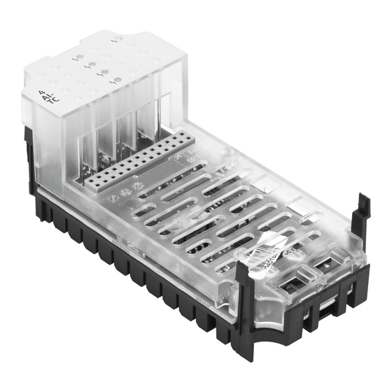
Anschluss des CPX-Terminals an. S Das Gerät enthält elektrostatisch gefährdete Bau- elemente. Berühren Sie deshalb keine Bauelemente. Beachten Sie die Handhabungsvorschriften für elektrostatisch gefährdete Bauelemente. Hinweis Nehmen Sie nur ein komplett montiertes und verdrahtetes CPX-Terminal in Betrieb. Festo CPX-CEC-Z6 1407b Deutsch... - Page 4 Anschluss- und Anzeigeelemente Status-LEDs RUN/STOP- Drehschalter Ethernet- Schnittstelle CPX-CEC-C1-V3/ -M1-V3: CANopen-Schnitt- stelle (Stecker, 9-polig Sub-D) CPX-CEC-S1-V3: RS232-Schnittstelle (Buchse, 9-polig, Sub-D) DIL-Schalter 1 DIL-Schalter 2 Anschluss für Handheld Typ CPX-MMI In der Grafik ist beispielhaft CPX-CEC-C1-V3/-M1-V3 abgebildet Festo CPX-CEC-Z6 1407b Deutsch...
- Page 5 STOP SPS Status: gestoppt (gelb) ERROR Laufzeitfehler SPS (rot) Ethernet-Verbindung: Link/Traffic (grün) Modify/Forcen aktiv (gelb) Systemfehler (rot) Lastversorgung (grün) Elektronikversorgung, Sensorversorgung (grün) Die LEDs RUN 1 und STOP 2 zeigen den Zustand des RUN/STOP- Drehschalters an. Festo CPX-CEC-Z6 1407b Deutsch...
- Page 6 – ggf. Druckluftversorgung – Betriebsspannungsversorgung Elektronik/Sensoren – Lastspannungsversorgung Ausgänge/Ventile 3.1 Montage/Demontage Das Gerät ist in einen Verkettungsblock des CPX-Terminals montiert. Schrauben, Anziehdrehmoment 0,9 … 1,1 Nm CPX-CEC-... Stromschienen Verkettungsblock (beliebig, hier beispielhaft ohne Einspeisung) Festo CPX-CEC-Z6 1407b Deutsch...
- Page 7 3. Drücken Sie das Gerät vorsichtig bis zum Anschlag in den Verkettungsblock. 4. Setzen Sie die Schrauben so an, dass die vorgefurchten Gewindegänge genutzt werden. 5. Ziehen Sie die Schrauben von Hand über Kreuz an. Anziehdrehmoment 0,9 … 1,1 Nm. Festo CPX-CEC-Z6 1407b Deutsch...
- Page 8 Terminierung (120 Ω) ein- bzw. ausschalten. CPX-CEC-C1-V3/-M1-V3 DIL-Schalter 2 Terminierung ausgeschaltet DIL 2.1: OFF DIL 2.2: OFF Terminierung eingeschaltet DIL 2.1: ON DIL 2.2: OFF Alle weiteren Schalterstellungen sind reserviert. Beim CPX-CEC-S1-V3 hat DIL-Schalter 2 keine Funktion. Festo CPX-CEC-Z6 1407b Deutsch...
- Page 9 0 = STOP Codesys-Controller gestoppt. Die LED STOP leuchtet gelb. 1 … F = RUN Codesys-Controller gestartet. Die LED RUN leuchtet grün. Die Schalterstellungen werden als Eingänge an die Steuerung wei- tergegeben und können dort ausgewertet werden. Festo CPX-CEC-Z6 1407b Deutsch...
- Page 10 Steckers ist an FE anzu- binden. Wird ein Motorcontroller mit externer Spannungsversorgung ange- schlossen, so darf Pin 6 am CPX-CEC-C1-V3/-M1-V3 nicht verwendet werden. FE: Funktionserde Die angeschlossenen CAN-Bus-Slaves werden über die CANopen-Schnittstelle nicht mit Spannung versorgt. Festo CPX-CEC-Z6 1407b Deutsch...
- Page 11 3.5 Pinbelegung der RS232-Schnittstelle (CPX-CEC-S1-V3) Buchse Signal Erläuterung n.c. nicht angeschlossen Empfangsdaten Sendedaten n.c. nicht angeschlossen Datenbezugspotential n.c. nicht angeschlossen n.c. nicht angeschlossen n.c. nicht angeschlossen n.c. nicht angeschlossen Schirm Schirm Verbindung zu Funktions- erde Festo CPX-CEC-Z6 1407b Deutsch...
- Page 12 Empfangsdaten+ n.c. nicht angeschlossen n.c. nicht angeschlossen RD– Empfangsdaten– n.c. nicht angeschlossen n.c. nicht angeschlossen Gehäuse Schirm Schirm Hinweis Weitere Informationen zu notwendigen Kabeln und Ste- ckern finden Sie in der Beschreibung des Codesys-Con- trollers P.BE-CPX-CEC-... Festo CPX-CEC-Z6 1407b Deutsch...
- Page 13 – Verkettungsblock mit Zusatzeinspeisung, wenn das Modul rechts vom CPX-CEC-... eine Zusatzeinspeisung benötigt, aber der Platz für die Zusatzeinspeisung nicht ausreicht. Hinweis Weitere Informationen zur Spannungsversorgung und den Verkettungsblöcken finden Sie in der CPX-System- beschreibung P.BE-CPX-SYS-... Festo CPX-CEC-Z6 1407b Deutsch...
- Page 14 – mit Pneumatik Typ MPA 18 ... 30 VDC Eigenstromaufnahme – bei Nennbetriebsspannung typ. 85 mA Netzausfallüberbrückung 10 ms Produktgewicht 155 g Abmessungen B x L x H 50 mm x 107 mm x 55 mm Festo CPX-CEC-Z6 1407b Deutsch...
-
Page 15: English
S The system contains electrostatically sensitive com- ponents. Do not therefore touch any contacts. Ob- serve the handling specifications for electrostatic sensitive devices. Note Only commission CPX terminals that have been fully assembled and wired. Festo CPX-CEC-Z6 1407b English... - Page 16 RUN/STOP rotary switch Ethernet interface CPX-CEC-C1-V3/ -M1-V3: CANopen interface (plug, 9-pin, Sub-D) CPX-CEC-S1-V3: RS232 interface (socket, 9-pin, Sub- DIL switch 1 DIL switch 2 Connection for handheld control unit type CPX-MMI The diagram shows the CPX-CEC-C1-V3/-M1-V3 Festo CPX-CEC-Z6 1407b English...
- Page 17 ERROR PLC runtime error (red) Ethernet connection: Link/traffic (green) Modify/force active (yellow) System fault (red) Load supply (green) Electronic supply, sensor supply (green) The RUN 1 and STOP 2 LEDs indicate the status of the RUN/STOP rotary switch. Festo CPX-CEC-Z6 1407b English...
- Page 18 – Load voltage supply for the outputs/valves 3.1 Mounting/dismounting The device is mounted in an interlinking block of the CPX terminal. Screws, tightening torque 0.9 ... 1.1 Nm CPX-CEC-... Contact rails Interlinking block (any, here without supply as an example) Festo CPX-CEC-Z6 1407b English...
- Page 19 3. Press the device carefully into the interlinking block as far as it will go. 4. Place the screws so that the self-cutting threads can be used. 5. Tighten the screws manually in diagonally opposite sequence. Tightening torque 0.9 ... 1.1 Nm. Festo CPX-CEC-Z6 1407b English...
- Page 20 DIL switch 2 Termination switched off DIL 2.1: OFF DIL 2.2: OFF Termination switched on DIL 2.1: ON DIL 2.2: OFF All other switch positions are reserved. On the CPX-CEC-S1-V3, DIL switch 2 has no function. Festo CPX-CEC-Z6 1407b English...
- Page 21 Codesys controller stopped. The STOP LED lights up yellow. 1 ... F = RUN Codesys controller started. The RUN LED lights up green. The switch positions are passed on to the controller as inputs and can be evaluated there. Festo CPX-CEC-Z6 1407b English...
- Page 22 FE Pin 6 on the CPX-CEC-C1-V3/-M1-V3 cannot be used if a motor controller with external power supply is connected. FE: Functional earth The connected CAN bus slaves are not supplied with voltage via the CANopen interface. Festo CPX-CEC-Z6 1407b English...
- Page 23 3.5 Pin allocation of the RS232 interface (CPX-CEC-S1-V3) Socket Signal Explanation n.c. Not connected Received data Transmitted data n.c. Not connected Data reference potential n.c. Not connected n.c. Not connected n.c. Not connected n.c. Not connected Screened Screened Connection to functional earth Festo CPX-CEC-Z6 1407b English...
- Page 24 Not connected n.c. Not connected RD– Received data– n.c. Not connected n.c. Not connected Housing Screened Screened Note Additional information on necessary cables and plugs can be found in the manual for the Codesys controller P.BE-CPX-CEC-... Festo CPX-CEC-Z6 1407b English...
- Page 25 CPX-CEC-... but there is not enough space for it. Note Further information on the power supply and interlink- ing blocks can be found in the CPX system manual P.BE-CPX-SYS-... Festo CPX-CEC-Z6 1407b English...
- Page 26 18 ... 30 V DC Intrinsic current consumption – At nominal operating voltage Typically 85 mA Power failure bridging 10 ms Product weight 155 g Dimensions W x L x H 50 mm x 107 mm x 55 mm Festo CPX-CEC-Z6 1407b English...
-
Page 27: Español
Por este motivo no se deben tocar los componentes. Observe las especificaciones sobre la manipulación de elementos sensibles a las descargas electrostáticas. Importante Ponga en funcionamiento un terminal CPX sólo cuando se halle completamente montado y cableado. Festo CPX-CEC-Z6 1407b Español... - Page 28 Interface CANopen (conector, sub-D de 9 polos) CPX-CEC-S1-V3: Interface RS232 (zócalo, de 9 polos, sub-D) Interruptor DIL 1 Interruptor DIL 2 Conexión para terminal de mano tipo CPX-MMI En el gráfico se representa como ejemplo CPX-CEC-C1-V3/-M1-V3 Festo CPX-CEC-Z6 1407b Español...
- Page 29 Conexión Ethernet: Link/Traffic (verde) Modify/Force activo (amarillo) Fallo del sistema (rojo) Alimentación de carga (verde) Alimentación de la electrónica, alimentación del sensor (verde) Los LED RUN 1 y STOP 2 indican el estado del conmutador giratorio RUN/STOP. Festo CPX-CEC-Z6 1407b Español...
- Page 30 3.1 Montaje y desmontaje El equipo está montado en un bloque de distribución del terminal CPX. Tornillos par de apriete 0,9 ... 1,1 Nm CPX-CEC-... Raíles de contacto Bloque distribuidor (como se quiera, aquí sin alimentación como ejemplo) Festo CPX-CEC-Z6 1407b Español...
- Page 31 3. Empuje el equipo con cuidado en el bloque de distribución hasta el tope. 4. Inserte los tornillos de forma que puedan utilizarse todos los pasos de rosca autocortantes. 5. Apriete los tornillos manualmente en secuencia diagonal. Par de apriete 0,9 ... 1,1 Nm. Festo CPX-CEC-Z6 1407b Español...
- Page 32 Interruptor DIL 2 Terminación desconectada DIL 2.1: OFF DIL 2.2: OFF Terminación conectada DIL 2.1: ON DIL 2.2: OFF Todas las demás posiciones del interruptor están reservadas. En el CPX-CEC-S1-V3 el interruptor DIL 2 no funciona. Festo CPX-CEC-Z6 1407b Español...
- Page 33 Controlador Codesys detenido. LED STOP encendido en amarillo. 1 ... F = RUN Controlador Codesys iniciado. LED RUN encendido en verde. Las posiciones del interruptor se transmiten al control en forma de entradas y pueden allí evaluarse. Festo CPX-CEC-Z6 1407b Español...
- Page 34 Si se conecta un controlador del motor con alimentación de corriente externa, no se puede utilizar el pin 6 en el CPX-CEC-C1-V3/-M1-V3. FE: Conexión a tierra Los slaves de bus CAN conectados no reciben tensión a través del interface CANopen. Festo CPX-CEC-Z6 1407b Español...
- Page 35 Explicaciones tipo zócalo n.c. no conectado Datos recibidos Datos enviados n.c. no conectado Potencial de datos de referencia n.c. no conectado n.c. no conectado n.c. no conectado n.c. no conectado Malla Malla Conexión a tierra funcional Festo CPX-CEC-Z6 1407b Español...
- Page 36 RD– Datos recibidos – n.c. no conectado n.c. no conectado Cuerpo Malla Malla Importante Hallará más información sobre los cables y conectores importantes en el manual del controlador Codesys P.BE-CPX-CEC-... Festo CPX-CEC-Z6 1407b Español...
- Page 37 CPX-CEC-... requiere una fuente de alimentación adicional, pero el espacio para dicha fuente no es suficiente. Importante Hallará más información sobre la alimentación de corriente y los bloques de distribución en el manual del sistema CPX P.BE-CPX-SYS-... Festo CPX-CEC-Z6 1407b Español...
- Page 38 – a la tensión nominal de típ. 85 mA funcionamiento Autonomía en caso de fallo de 10 ms tensión Peso del producto 155 g Dimensiones: ancho x largo x alto 50 mm x 107 mm x 55 mm Festo CPX-CEC-Z6 1407b Español...
-
Page 39: Français
électrostatiques. Ne pas toucher ces composants. Respecter les consignes concernant la manipulation des composants sen- sibles aux charges électrostatiques. Nota Mettre le terminal CPX en service uniquement lorsque le montage et le raccordement sont complètement terminés. Festo CPX-CEC-Z6 1407b Français... - Page 40 -M1-V3 : Interface CANopen (connecteur, Sub-D 9 pôles) CPX-CEC-S1-V3 : Interface de prog- rammation RS232 (connecteur femelle Sub-D 9 pôles) Interrupteur DIL 1 Interrupteur DIL 2 Raccord pour console type CPX-MMI L’illustration représente à titre d’exemple CPX-CEC-C1-V3/-M1-V3 Festo CPX-CEC-Z6 1407b Français...
- Page 41 (rouge) Connexion Ethernet : Lien/trafic (vert) Modifier/forçage actif (jaune) Erreur système (rouge) Alimentation de puissance (verte) Alimentation de l’électronique, alimentation des capteurs (verte) Les LED RUN 1 et STOP 2 indiquent l’état du commutateur rotatif RUN/STOP. Festo CPX-CEC-Z6 1407b Français...
- Page 42 – l’alimentation des sorties/des distributeurs 3.1 Montage/Démontage L’appareil est monté dans un module d’interconnexion du terminal CPX. Vis, couple de serrage 0,9 ... 1,1 Nm CPX-CEC-... Rails conducteurs Module d’interconnexion (au choix, ici par exemple sans alimentation) Festo CPX-CEC-Z6 1407b Français...
- Page 43 3. Enfoncer précautionneusement l’appareil dans le module d’interconnexion jusqu’en butée. 4. Positionner les vis de manière à utiliser les filets existants. 5. Serrer manuellement les vis en diagonale. Couple de serrage 0,9 ... 1,1 Nm. Festo CPX-CEC-Z6 1407b Français...
- Page 44 Terminaison désactivée DIL 2.1 : OFF DIL 2.2 : OFF Terminaison activée DIL 2.1 : ON DIL 2.2 : OFF Tous les autres réglages des interrupteurs sont réservés. Sur le CPX-CEC-S1-V3, l’interrupteur DIL 2 est sans fonction. Festo CPX-CEC-Z6 1407b Français...
- Page 45 Contrôleur Codesys arrêté. La LED STOP jaune s’allume. 1 ... F = RUN Contrôleur Codesys démarré. La LED RUN verte s’allume. Les réglages du commutateur sont transmis comme entrées à la commande et peuvent y être analysés. Festo CPX-CEC-Z6 1407b Français...
- Page 46 Si un contrôleur moteur à alimentation externe est raccordé, la broche 6 du CPX-CEC-C1-V3/-M1-V3 ne doit alors pas être utilisée. FE : terre fonctionnelle Les esclaves du bus CAN connectés ne sont pas alimentés en tension via l’interface CANopen. Festo CPX-CEC-Z6 1407b Français...
- Page 47 Données reçues Données émises n.c. non connecté Potentiel de référence des données n.c. non connecté n.c. non connecté n.c. non connecté n.c. non connecté Blindage Blindage Connexion à la terre du système Festo CPX-CEC-Z6 1407b Français...
- Page 48 RD– Données reçues– n.c. non connecté n.c. non connecté Boîtier Blindage Blindage Nota Pour plus d’informations sur les câbles et les connec- teurs nécessaires, se reporter au manuel du contrôleur Codesys P.BE-CPX-CEC-... Festo CPX-CEC-Z6 1407b Français...
- Page 49 à droite du CPX-CEC-... requiert une alimentation auxiliaire, mais que l’emplacement d’ali- mentation auxiliaire est insuffisant. Nota Pour plus d’informations sur l’alimentation et les mo- dules d’interconnexion, se reporter au manuel du sys- tème CPX P.BE-CPX-SYS-... Festo CPX-CEC-Z6 1407b Français...
- Page 50 – avec tension de service typ. 85 mA nominale Autonomie en cas de coupure de 10 ms courant Poids du produit 155 g Dimensions l x L x h 50 mm x 107 mm x 55 mm Festo CPX-CEC-Z6 1407b Français...
-
Page 51: Italiano
S L’apparecchio contiene componenti sensibili alle correnti elettrostatiche. Pertanto non toccare tali componenti. Osservare le prescrizioni di impiego dei componenti sensibili alle cariche elettrostatiche. Nota Utilizzare solo un terminale CPX completamente assemblato e cablato. Festo CPX-CEC-Z6 1407b Italiano... - Page 52 Interfaccia CANopen (connettore, Sub-D a 9 poli) CPX-CEC: Interfaccia RS232 (connettore fem- mina Sub-D a 9 poli) Interruttore DIL 1 Interruttore DIL 2 Attacco per handheld tipo CPX-MMI Nel grafico è rappresentato, come esempio, il CPX-CEC-C1/-M1 Festo CPX-CEC-Z6 1407b Italiano...
- Page 53 (rosso) Collegamento Ethernet: Link/Traffic (verde) Modify/Forcing attivo (giallo) Errore di sistema (rosso) Alimentazione di carico (verde) Alimentazione dei componenti elettronici, Alimentazione sensori (verde) I LED RUN 1 e STOP 2 mostrano lo stato dell’interruttore rotante RUN/STOP. Festo CPX-CEC-Z6 1407b Italiano...
- Page 54 3.1 Montaggio / Smontaggio L’apparecchio è installato in un blocco di interconnessione del terminale CPX. Viti, Coppia di serraggio 0,9 ... 1,1 Nm CPX-CEC-... Barre conduttrici Blocco di interconnessione (qualsiasi, qui un esempio senza modulo di alimentazione) Festo CPX-CEC-Z6 1407b Italiano...
- Page 55 3. Premere l’apparecchio cautamente nel blocco di interconnessione fino alla battuta. 4. Per il serraggio delle viti utilizzare solamente il filetto già presente. 5. Stringere le viti manualmente incrociando. Coppia di serraggio 0,9 ... 1,1 Nm. Festo CPX-CEC-Z6 1407b Italiano...
- Page 56 CPX-CEC-C1/-M1 Interruttore DIL 2 Tempificazione disattivata DIL 2.1: OFF DIL 2.2: OFF Tempificazione attivata DIL 2.1: ON DIL 2.2: OFF Tutte le altre posizioni dell’interruttore sono riservate. Nel CPX-CEC-S1-V3 l’interruttore DIL 2 non ha alcuna funzione. Festo CPX-CEC-Z6 1407b Italiano...
- Page 57 Controller Codesys arrestato. Il LED STOP giallo è acceso. 1 ... F = RUN Controller Codesys avviato. Il LED RUN verde è acceso. Le posizioni dell’interruttore vengono trasmesse come ingressi al sistema di comando, dove possono essere analizzate. Festo CPX-CEC-Z6 1407b Italiano...
- Page 58 Non utilizzare il pin 6 sul CPX-CEC-C1/M1, se un regolatore dell’attuatore viene collegato all’alimentazione di tensione esterna. FE: Messa a terra Gli slave del bus CAN collegati non vengono alimentati di corrente tramite l’interfaccia CANopen. Festo CPX-CEC-Z6 1407b Italiano...
- Page 59 Spiegazione femmina n.c. Non collegato Dati di ricezione Dati di trasmissione n.c. Non collegato Potenziale riferimento dati n.c. Non collegato n.c. Non collegato n.c. Non collegato n.c. Non collegato Schermo Schermo Connessione di messa a terra Festo CPX-CEC-Z6 1407b Italiano...
- Page 60 Non collegato n.c. Non collegato RD– Dati di ricezione– n.c. Non collegato n.c. Non collegato Corpo Schermo Schermo Nota Ulteriori informazioni relative ai cavi e ai connettori necessari sono riportate nella descrizione del controller Codesys P.BE-CPX-CEC-... Festo CPX-CEC-Z6 1407b Italiano...
- Page 61 Blocco di interconnessione se il modulo a destra del CPX-CEC-... richiede un’alimentazione supplementare, però lo spazio per questa alimentazione non è suffi- ciente. Nota Per ulteriori informazioni relative all’alimentazione di tensione e ai blocchi di interconnessione si rimanda alla descrizione del sistema CPX P.BE-CPX-SYS-... Festo CPX-CEC-Z6 1407b Italiano...
- Page 62 – Con tensione d’esercizio tipo 85 mA nominale Autonomia in caso di caduta di 10 ms corrente Peso del prodotto 155 g Dimensioni L x L x A 50 mm x 107 mm x 55 mm Festo CPX-CEC-Z6 1407b Italiano...
- Page 63 中文 用户提示 Codesys CPX-CEC-... (P.BE-CPX-CEC-...) (P.BE-CPX-SYS-...) 警告 • • IEC/DIN EN 60204-1 IEC/DIN EN 60204-1 (PELV) • • 注意 Festo CPX-CEC-Z6 1112a 中文...
- Page 64 接线和显示元件 RUN/STOP CPX-CEC-C1-V3/ -M1-V3: 口 CANopen Sub-D CPX-CEC-S1-V3: RS232 Sub-D 座 于 CPX-MMI 手提装 口 CPX-CEC-C1-V3/-M1-V3 Festo CPX-CEC-Z6 1112a 中文...
- Page 65 状态指示灯 已 STOP 已 止 运 错误 ERROR 以太网 Link Traffic 修改 Modify 实施 Forcen 激活 错误 子装 供 感 供 STOP RUN/STOP Festo CPX-CEC-Z6 1112a 中文...
- Page 66 安装说明 警告 3.1 安装/拆卸 0.9 ... 1.1 Nm CPX-CEC-... 触轨 Festo CPX-CEC-Z6 1112a 中文...
- Page 67 注意 0.9 ... 1.1 Nm Festo CPX-CEC-Z6 1112a 中文...
- Page 68 3.2 设定 DIL 开关 DIL 开关 1 DIL 开关 1 CPX-CEC-... DIL 1.1 DIL 1.2 DIL 开关 2 CPX-CEC-C1-V3/-M1-V3 (120 Ω) DIL 开关 2 CPX-CEC- C1-V3/-M1-V3 DIL 2.1 DIL 2.2 DIL 2.1 DIL 2.2 CPX-CEC-S1-V3 Festo CPX-CEC-Z6 1112a 中文...
- Page 69 3.3 设定 RUN/STOP 旋转开关 注意 RUN/STOP “0” (STOP) 设定 旋转开关 0 = STOP 机 STOP Codesys 亮 1 ... F = RUN Codesys 亮 号 那里 分析 处理 Festo CPX-CEC-Z6 1112a 中文...
- Page 70 点接通 未 n.c. CAN_L CAN_GND 未 n.c. 2 ) CAN_SHLD 1 ) 选 CAN_GND 高 CAN_H 未 n.c. 未 n.c. 外壳 外壳 须 2 ) 处 如果马 外 则 允许 脚 CPX-CEC-C1-V3/-M1-V3 性 从 经 CANopen Festo CPX-CEC-Z6 1112a 中文...
- Page 71 3.5 RS232 接口的针脚分配 (CPX-CEC-S1-V3) 插座 针脚 信号 解释 未 n.c. 收数据 送数据 未 n.c. 数据 参照 未 n.c. 未 n.c. 未 n.c. 未 n.c. 屏蔽 屏蔽 Festo CPX-CEC-Z6 1112a 中文...
- Page 72 3.6 以太网接口的针脚分配 插座 针脚 信号 解释 送数据 送数据 TD– – 收数据 未 n.c. 未 n.c. 收数据 RD– – 未 n.c. 未 n.c. 壳体 屏蔽 屏蔽 注意 需 缆 参见 Codesys P.BE-CPX-CEC-... Festo CPX-CEC-Z6 1112a 中文...
- Page 73 3.7 电源 由 馈送 数 需 由此 组 带 带 带辅 — 当 CPX-CEC-... 右 需 辅 而 际 间又 注意 P.BE-CPX-SYS-... 更多 Festo CPX-CEC-Z6 1112a 中文...
- Page 74 20.4 ... 26.4 VDC 18 ... 30 VDC –带 MPA 自身电流消耗 典 – 额定工 时 85 mA 电源断电缓冲 10 ms 产品重量 155 g 尺寸 宽 x 长 x 高 50 mm x 107 mm x 55 mm Festo CPX-CEC-Z6 1112a 中文...
Need help?
Do you have a question about the CPX Series and is the answer not in the manual?
Questions and answers