Festo CPX-CEC-C1 Manual
Cpx terminal codesys controller
Hide thumbs
Also See for CPX-CEC-C1:
- Electronic manual (84 pages) ,
- Manual (74 pages) ,
- Electronic manual (87 pages)

Related Manuals for Festo CPX-CEC-C1


Summary of Contents for Festo CPX-CEC-C1
- Page 1 CPX Terminal Kurz beschreibung Brief description CoDeSys− Controller CPX−CEC−C1 Deutsch English Español Français Italiano Svenska 745914 0907NH...
-
Page 2: Table Of Contents
Edition: 0907NH Original: de © (Festo AG & Co. KG, D 73726 Esslingen, Germany, 2009) Internet: http://www.festo.com E−Mail: service_international@festo.com Festo P.BE−K−CPX−CEC 0907NH... -
Page 3: Deutsch
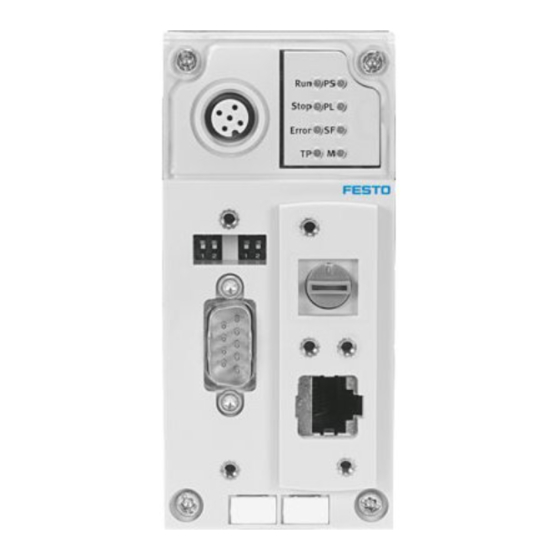
Anschluss des CPX−Terminals an. S Der CPX−CEC−C1 enthält elektrostatisch gefährdete Bauelemente. Berühren Sie deshalb keine Bauele mente. Beachten Sie die Handhabungsvorschriften für elektrostatisch gefährdete Bauelemente. Hinweis Nehmen Sie nur ein komplett montiertes und verdrahtetes CPX−Terminal in Betrieb. Festo P.BE−K−CPX−CEC 0907NH Deutsch... - Page 4 Anschluss− und Anzeigeelemente Status−LEDs RUN/STOP− Drehschalter Ethernet− Schnittstelle CANopen Schnitt stelle ( 9−poliger Sub−D Stecker) DIL−Schalter 1 DIL−Schalter 2 Anschluss für Handheld Typ CPX−MMI Festo P.BE−K−CPX−CEC 0907NH Deutsch...
- Page 5 STOP SPS Status: gestoppt (gelb) ERROR Laufzeitfehler SPS (rot) Ethernet−Verbindung: Link/Traffic (grün) Modify/Forcen aktiv (gelb) Systemfehler (rot) Lastversorgung (grün) Elektronikversorgung, Sensorversorgung (grün) Die LEDs RUN 1 und STOP 2 zeigen den Zustand des RUN/STOP− Drehschalters an. Festo P.BE−K−CPX−CEC 0907NH Deutsch...
- Page 6 Schalten Sie vor Installations− und Wartungsarbeiten folgendes aus: ggf. Druckluftversorgung Betriebsspannungsversorgung Elektronik/Sensoren Lastspannungsversorgung Ausgänge/Ventile 3.1 Montage/Demontage Der CoDeSys−Controller CPX−CEC−C1 ist in einen Ver kettungsblock des CPX−Terminals montiert. Schrauben, Anzugsdrehmoment 1,1 Nm CPX−CEC−C1 Stromschienen Verkettungsblock (beliebig, hier beispielhaft ohne Einspeisung) Festo P.BE−K−CPX−CEC 0907NH Deutsch...
- Page 7 3. Drücken Sie den CPX−CEC−C1 vorsichtig bis zum Anschlag in den Verkettungsblock. 4. Setzen Sie die Schrauben so an, dass die vorgefurchten Gewindegänge genutzt werden. 5. Ziehen Sie die Schrauben von Hand über Kreuz an. Anzugsdrehmoment 0,9 1,1 Nm. Festo P.BE−K−CPX−CEC 0907NH Deutsch...
- Page 8 Mit DIL−Schalter 2 können Sie die CAN−Bus Terminierung (120 ) ein− bzw. ausschalten. CPX−CEC−C1 DIL−Schalter 2 Terminierung ausgeschaltet DIL 2.1: OFF DIL 2.2: OFF Terminierung eingeschaltet DIL 2.1: ON DIL 2.2: OFF Alle weiteren Schalterstellungen sind reserviert. Festo P.BE−K−CPX−CEC 0907NH Deutsch...
- Page 9 Drehschalter 0 = STOP CPX−CEC−C1 gestoppt. Die LED STOP leuchtet gelb. F = RUN CPX−CEC−C1 gestartet. Die LED RUN leuchtet grün. Die Schalterstellungen werden als Eingänge an die Steuerung weiter gegeben und können dort ausgewertet werden. Festo P.BE−K−CPX−CEC 0907NH Deutsch...
- Page 10 FE anzubinden. Wird ein Antriebsregler mit externer Spannungsversorgung ange− schlossen, so darf CAN Ground (optional), Pin 6, am CPX−CEC−C1 nicht verwendet werden. FE: Funktionserde Die angeschlossenen CAN−Bus−Slaves werden über die CANopen−Schnittstelle nicht mit Spannung versorgt. Festo P.BE−K−CPX−CEC 0907NH Deutsch...
- Page 11 3.5 Pinbelegung der Ethernet−Schnittstelle Buchse Signal Erläuterung Sendedaten+ Sendedaten Empfangsdaten+ n.c. nicht angeschlossen n.c. nicht angeschlossen Empfangsdaten n.c. nicht angeschlossen n.c. nicht angeschlossen Metall Shield Schirm umhüllung Festo P.BE−K−CPX−CEC 0907NH Deutsch...
- Page 12 Verkettungsblock mit Systemeinspeisung. Verkettungsblock mit Zusatzeinspeisung, wenn das Modul rechts vom CPX−CEC−C1 eine Zusatzeinspeisung benötigt, aber der Platz für die Zusatzeinspeisung nicht ausreicht. Hinweis Weitere Informationen zur Spannungsversorgung und den Verkettungsblöcken finden Sie in der CPX−System beschreibung P.BE−CPX−SYS−... Festo P.BE−K−CPX−CEC 0907NH Deutsch...
- Page 13 Pneumatik Typ CPA 20,4 26,4 VDC mit Pneumatik Typ MPA 30 VDC Eigenstromaufnahme bei Nennbetriebsspannung typ. 85 mA Netzausfallüberbrückung 10 ms Produktgewicht 155 g Abmessungen B x L x H 50 mm x 107 mm x 55 mm Festo P.BE−K−CPX−CEC 0907NH Deutsch...
- Page 14 Festo P.BE−K−CPX−CEC 0907NH Deutsch...
-
Page 15: English
S The CPX−CEC−C1 contains electrostatically sensitive devices. Therefore, do not touch any contacts. Ob serve the handling specifications for electrostatically sensitive devices. Note Only commission a CPX terminal if it has been has been fitted and wired completely. Festo P.BE−K−CPX−CEC 0907NH English... - Page 16 Connection and display components Status LEDs RUN/STOP rotary switch Ethernet interface CANopen interface (9−pin Sub−D plug) DIL switch 1 DIL switch 2 Connection for Handheld type CPX−MMI Festo P.BE−K−CPX−CEC 0907NH English...
- Page 17 ERROR PLC runtime error (red) Ethernet connection: link/traffic (green) Modify/force active (yellow) System fault (red) Load supply (green) Electronic supply, sensor supply (green) The LEDs RUN 1 and STOP 2 show the status of the RUN/STOP rotary switch. Festo P.BE−K−CPX−CEC 0907NH English...
- Page 18 The load voltage supply for the outputs/valves 3.1 Mounting/Dismounting The CoDeSys controller CPX−CEC−C1 is mounted in an inter linking block of the CPX terminal. Screws, tightening torque 1.1 Nm CPX−CEC−C1 Contact rails Interlinking block (any, example shown without supply) Festo P.BE−K−CPX−CEC 0907NH English...
- Page 19 3. Push the CPX−CEC−C1 as far as possible into the interlinking block carefully and without tilting. 4. Place the screws so that the self−cutting threads can be used. 5. Tighten the screws by hand in diagonally opposite sequence. Tightening torque 0.9 1.1 Nm. Festo P.BE−K−CPX−CEC 0907NH English...
- Page 20 With DIL switch 2, you can switch the CAN bus termination (120 ) on or off. CPX−CEC−C1 DIL switch 2 Termination switched off DIL 2.1: OFF DIL 2.2: OFF Termination switched on DIL 2.1: ON DIL 2.2: OFF All further switch settings are reserved. Festo P.BE−K−CPX−CEC 0907NH English...
- Page 21 0 = STOP CPX−CEC−C1 stopped. The STOP LED lights up yellow. F = RUN CPX−CEC−C1 started. The RUN LED lights up green. The switch settings are transferred to the controller as inputs, where they can be evaluated. Festo P.BE−K−CPX−CEC 0907NH English...
- Page 22 If a drive controller with external power supply is connected, CAN ground (optional), pin 6, on the CPX−CEC−C1 must not be used. FE: Functional earth The connected CAN bus slaves are not supplied with power via the CANopen interface. Festo P.BE−K−CPX−CEC 0907NH English...
- Page 23 3.5 Pin allocation for the Ethernet interface Socket Signal Explanation Transmitted data+ Transmitted data Received data+ n.c. Not connected n.c. Not connected Received data n.c. Not connected n.c. Not connected Metal Screened Screened covering Festo P.BE−K−CPX−CEC 0907NH English...
- Page 24 CPX−CEC−C1 requires an additional supply, but the space is not sufficient for the additional supply. Note Additional information on the power supply and the interlinking blocks can be found in the CPX system de scription P.BE−CPX−SYS−... Festo P.BE−K−CPX−CEC 0907NH English...
- Page 25 With pneumatics of type MPA 30 VDC Intrinsic current consumption At nominal operating voltage Typically 85 mA Power failure buffering 10 ms Product weight 155 g Dimensions W x L x H 50 mm x 107 mm x 55 mm Festo P.BE−K−CPX−CEC 0907NH English...
- Page 26 Festo P.BE−K−CPX−CEC 0907NH English...
-
Page 27: Español
S El CPX−CEC−C1 contiene elementos sensibles a las descargas electrostáticas. No toque ninguno de los componentes. Observe las especificaciones sobre manipulación de elementos sensibles a las descargas electrostáticas. Importante Ponga en servicio el terminal CPX sólo cuando se halle completamente montado y cableado. Festo P.BE−K−CPX−CEC 0907NH Español... - Page 28 Elementos de conexión e indicación LEDs de estado Interruptor giratorio RUN/STOP Interface Ethernet Interface CANopen (clavija sub−D de 9 pines) Interruptor DIL 1 Interruptor DIL 2 Conexión para terminal de mano tipo CPX−MMI Festo P.BE−K−CPX−CEC 0907NH Español...
- Page 29 Link/Traffic (verde) Modify/Force activo (amarillo) Fallo del sistema (rojo) Alimentación de carga (verde) Alimentación de la electrónica, alimen− tación de sensores (verde) Los LEDs RUN 1 y STOP 2 indican el estado del interruptor gira− torio RUN/STOP. Festo P.BE−K−CPX−CEC 0907NH Español...
- Page 30 3.1 Montaje/Desmontaje El controlador CoDeSys CPX−CEC−C1 está montado en un bloque distribuidor del terminal CPX. Tornillos, par de apriete 1,1 Nm CPX−CEC−C1 Raíles de contacto Bloque distribuidor (indiferente, aquí sin alimentación como ejemplo) Festo P.BE−K−CPX−CEC 0907NH Español...
- Page 31 3. Presione con cuidado el CPX−CEC−C1 en el bloque distribuidor hasta el tope. 4. Inserte los tornillos de forma que puedan utilizarse las roscas autocortantes. 5. Apriete los tornillos a mano en secuencia diagonal alternativa. Par de apriete 0,9 1,1 Nm. Festo P.BE−K−CPX−CEC 0907NH Español...
- Page 32 Con el interruptor DIL 2 puede conectar y desconectar la terminación del bus CAN (120 ). CPX−CEC−C1 Interruptor DIL 2 Terminación desconectada DIL 2.1: OFF DIL 2.2: OFF Terminación conectada DIL 2.1: ON DIL 2.2: OFF Las otras posiciones de interruptor están reservadas. Festo P.BE−K−CPX−CEC 0907NH Español...
- Page 33 0 = STOP CPX−CEC−C1 parado. LED STOP encendido en amarillo. F = RUN CPX−CEC−C1 en funcionamiento. LED RUN encendido en verde. Las posiciones del interruptor se transmiten al control en forma de entradas y pueden allí evaluarse. Festo P.BE−K−CPX−CEC 0907NH Español...
- Page 34 Si se conecta un control para accionamientos con alimentación externa, no debe utilizarse entonces CAN Ground (pin 6) (opcional) en el CPX−CEC−C1. FE: Tierra funcional Los slaves de bus CAN conectados no reciben tensión a través del interface CANopen. Festo P.BE−K−CPX−CEC 0907NH Español...
- Page 35 3.5 Ocupación de clavijas del interface Ethernet Zócalo Señal Explicación Datos transmitidos+ Datos transmitidos Datos recibidos+ n.c. No conectado n.c. No conectado Datos recibidos n.c. No conectado n.c. No conectado Recubri Shield Apantallamiento miento metálico Festo P.BE−K−CPX−CEC 0907NH Español...
- Page 36 CPX−CEC−C1 requiere una fuente de alimentación adicional, pero el espacio para dicha fuente no es suficiente. Importante Encontrará más información sobre la alimentación y los bloques distribuidores en el manual del sistema CPX P.BE−CPX−SYS−... Festo P.BE−K−CPX−CEC 0907NH Español...
- Page 37 Típ. 85 mA nominal Autonomía en caso de fallo de 10 ms la red Peso del producto 155 g Dimensiones (La x An x Al) 50 mm x 107 mm x 55 mm Festo P.BE−K−CPX−CEC 0907NH Español...
- Page 38 Festo P.BE−K−CPX−CEC 0907NH Español...
-
Page 39: Français
électrostatiques. Il ne faut donc pas toucher ces composants. Respectez les consignes concernant la manipulation des composants sen− sibles aux charges électrostatiques. Nota Mettez le terminal CPX en service uniquement lorsque le montage et le raccordement sont complètement terminés. Festo P.BE−K−CPX−CEC 0907NH Français... - Page 40 Eléments de signalisation et de connexion LED d’état Commutateur rotatif RUN/STOP Interface Ethernet Interface CANopen (connecteur Sub−D à 9 pôles) Micro−interrupteur DIL 1 Micro−interrupteur DIL 2 Raccord pour console manuelle de type CPX−MMI Festo P.BE−K−CPX−CEC 0907NH Français...
- Page 41 Connexion Ethernet : Lien/trafic (vert) Modifier/forçage actif (jaune) Erreur système (rouge) Alimentation de puis− sance (verte) Alimentation de l’électronique, Alimentation des capteurs (verte) Les LED RUN 1 et STOP 2 indiquent l’état du commutateur rotatif RUN/STOP. Festo P.BE−K−CPX−CEC 0907NH Français...
- Page 42 3.1 Montage/démontage Le contrôleur CoDeSys CPX−CEC−C1 est monté dans un module d’interconnexion du terminal CPX. Vis, Couple de serrage 1,1 Nm CPX−CEC−C1 Rails conducteurs Module d’inter− connexion (au choix, ici par exemple sans alimentation) Festo P.BE−K−CPX−CEC 0907NH Français...
- Page 43 3. Enfoncez avec précaution le CPX−CEC−C1 dans le module d’interconnexion jusqu’en butée. 4. Positionnez les vis de manière à utiliser les filets existants. 5. Serrez les vis en diagonale à la main. Couple de serrage 0,9 1,1 Nm. Festo P.BE−K−CPX−CEC 0907NH Français...
- Page 44 CAN (120 ). CPX−CEC−C1 Micro−interrupteur DIL 2 Terminaison désactivée DIL 2.1 : OFF DIL 2.2 : OFF Terminaison activée DIL 2.1 : ON DIL 2.2 : OFF Tous les autres réglages des interrupteurs sont réservés. Festo P.BE−K−CPX−CEC 0907NH Français...
- Page 45 0 = STOP CPX−CEC−C1 arrêté. La LED STOP jaune s’allume. F = RUN CPX−CEC−C1 démarré. La LED RUN verte s’allume. Les réglages du commutateur sont transmis comme entrées à la commande et peuvent y être analysés. Festo P.BE−K−CPX−CEC 0907NH Français...
- Page 46 Si un régulateur d’entraînement à alimentation électrique externe est connecté, il est impossible d’utiliser le CAN Ground (en option) sur la broche 6 du CPX−CEC−C1. FE : terre fonctionnelle Les esclaves du bus CAN connectés ne sont pas alimentés en tension via l’interface CANopen. Festo P.BE−K−CPX−CEC 0907NH Français...
- Page 47 3.5 Affectation des broches de l’interface Ethernet Connecteur Broche Signal Commentaire femelle Données émises+ Données émises Données reçues+ n.c. non connecté n.c. non connecté Données reçues n.c. non connecté n.c. non connecté Enveloppe Shield Blindage métallique Festo P.BE−K−CPX−CEC 0907NH Français...
- Page 48 à droite du CPX−CEC−C1 requiert une alimentation auxiliaire, mais que l’emplacement d’alimentation auxiliaire est insuffisant. Nota Pour plus d’informations sur l’alimentation électrique et les modules d’interconnexion, veuillez vous reporter à la description du système CPX P.BE−CPX−SYS−... Festo P.BE−K−CPX−CEC 0907NH Français...
- Page 49 85 mA nominale Autonomie en cas de coupure de 10 ms courant Poids du produit 155 g Dimensions L x P x H 50 mm x 107 mm x 55 mm Festo P.BE−K−CPX−CEC 0907NH Français...
- Page 50 Festo P.BE−K−CPX−CEC 0907NH Français...
-
Page 51: Italiano
S Il CPX−CEC−C1 contiene componenti sensibili alle correnti elettrostatiche. Pertanto non toccare tali componenti. Attenersi alle prescrizioni di impiego dei componenti sensibili alle correnti elettrostatiche. Nota Utilizzare solamente un terminale CPX completamente assemblato e cablato. Festo P.BE−K−CPX−CEC 0907NH Italiano... - Page 52 Elementi di connessione e segnalazione LED di stato Interruttore rotativo RUN/STOP Interfaccia Ethernet Interfaccia CANopen (connettore Sub−D a 9 poli) Interruttore DIL 1 Interruttore DIL 2 Attacco per handheld tipo CPX−MMI Festo P.BE−K−CPX−CEC 0907NH Italiano...
- Page 53 (rosso) Collegamento Ethernet: Link/Traffic (verde) Modify/Forcing attivo (giallo) Errore di sistema (rosso) Alimentazione di carico (verde) Alimentazione dei componenti elettronici, alimentazione sensori (verde) I LED RUN 1 e STOP 2 mostrano lo stato dell’interruttore rotativo RUN/STOP Festo P.BE−K−CPX−CEC 0907NH Italiano...
- Page 54 Il controller CoDeSys CPX−CEC−C1 è montato in una sotto base di collegamento elettrico del terminale CPX. Viti, coppia di serraggio 1,1 Nm CPX−CEC−C1 Barre conduttrici Sottobase di collegamento elettrico (qualsiasi, qui un esempio senza modulo di alimentazione) Festo P.BE−K−CPX−CEC 0907NH Italiano...
- Page 55 3. Reinserire con cautela il CPX−CEC−C1 nella sottobase di collegamento elettrico fino all’arresto meccanico. 4. Per il serraggio delle viti utilizzare solamente il filetto già presente. 5. Stringere manualmente le viti in sequenza incrociata. Coppia di serraggio 0,9 1,1 Nm. Festo P.BE−K−CPX−CEC 0907NH Italiano...
- Page 56 Con l’interruttore DIL 2 è possibile attivare o disattivare la tempificazione del bus CAN (120 ). CPX−CEC−C1 Interruttore DIL 2 Tempificazione disattivata DIL 2.1: OFF DIL 2.2: OFF Tempificazione attivata DIL 2.1: ON DIL 2.2: OFF Tutte le altre posizioni dell’interruttore sono riservate. Festo P.BE−K−CPX−CEC 0907NH Italiano...
- Page 57 0 = STOP CPX−CEC−C1 arrestato. Il LED STOP giallo è acceso. F = RUN CPX−CEC−C1 arrestato. Il LED RUN verde è acceso. Le posizioni dell’interruttore vengono trasmesse come ingressi al sistema di comando, dove possono essere analizzate. Festo P.BE−K−CPX−CEC 0907NH Italiano...
- Page 58 Non utilizzare il CAN Ground (opzionale), pin 6, sul CPX−CEC−C1, se un regolatore dell’attuatore viene collegato all’alimentazione di tensione esterna. FE: messa a terra Gli slave del bus CAN non vengono alimentati di corrente tramite l’interfaccia CANopen. Festo P.BE−K−CPX−CEC 0907NH Italiano...
- Page 59 3.5 Occupazione dei pin dell’interfaccia Ethernet Presa Segnale Spiegazione Dati di trasmissione+ Dati di trasmissione Dati di ricezione+ n.c. Non collegato n.c. Non collegato Dati di ricezione n.c. Non collegato n.c. Non collegato Rivesti Shield Schermo mento in metallo Festo P.BE−K−CPX−CEC 0907NH Italiano...
- Page 60 CPX−CEC−C1 richiede una alimentazione supplementare, ma lo spazio per tale alimentazione non è sufficiente. Nota Ulteriori informazioni relative all’alimentazione di tensione e alle sottobasi di collegamento elettrico sono riportate nella descrizione del sistema CPX P.BE− CPX−SYS−... Festo P.BE−K−CPX−CEC 0907NH Italiano...
- Page 61 Assorbimento elettrico interno Con tensione d’esercizio Standard 85 mA nominale Autonomia in caso di caduta di 10 ms corrente Peso 155 g Dimensioni largh. x lungh. x alt. 50 mm x 107 mm x 55 mm Festo P.BE−K−CPX−CEC 0907NH Italiano...
- Page 62 Festo P.BE−K−CPX−CEC 0907NH Italiano...
-
Page 63: Svenska
S Anslut en jordledare med tillräcklig kabelarea till den anslutning på CPX−terminalen som är märkt med jordsymbolen. S CPX−CEC−C1 innehåller elektrostatiskt känsliga komponenter. Vidrör därför inga komponenter. Följ hanteringsföreskrifterna för elektrostatiskt känsliga komponenter. Information Ta endast en komplett monterad och ansluten CPX−terminal i drift. Festo P.BE−K−CPX−CEC 0907NH Svenska... - Page 64 Anslutnings− och indikeringselement Status−lysdioder RUN/STOP−vridomk opplare Ethernet−gränssnitt CANopen−gränssnitt (9−polig D−sub− hankontakt) DIL−omkopplare 1 DIL−omkopplare 2 Anslutning för handterminal typ CPX−MMI Festo P.BE−K−CPX−CEC 0907NH Svenska...
- Page 65 PLC status: startat (grön) STOP PLC status: stoppad (gul) ERROR Gångtidsfel PLC (röd) Ethernet−förbindelse: Link/Traffic (grön) Modify/tvångsstyrning aktiv (gul) Systemfel (röd) Lastspännings− försörjning (grön) Elektronikförsörjning, givarförsörjning (grön) Lysdioderna RUN 1 och STOP 2 indikerar RUN/STOP−vridomkopplarens status. Festo P.BE−K−CPX−CEC 0907NH Svenska...
- Page 66 Tryckluftsmatning (om sådan föreligger) Matningsspänning elektronik/givare Lastspänningsförsörjning för utgångar/ventiler 3.1 Montering/demontering CoDeSys−Controller CPX−CEC−C1 är monterad i ett kopplingsblock på CPX−terminalen. Skruvar, åtdragningsmoment 1,1 Nm CPX−CEC−C1 Strömskenor Kopplingsblock (valfritt, här som exempel utan extra matning) Festo P.BE−K−CPX−CEC 0907NH Svenska...
- Page 67 CPX−CEC−C1 över strömskenorna. 3. Tryck försiktigt in CPX−CEC−C1 till anslag i kopplings− blocket. 4. Placera skruvarna i de gängade spåren. 5. Dra åt skruvarna korsvis och för hand. Åtdragningsmoment 0,9 1,1 Nm. Festo P.BE−K−CPX−CEC 0907NH Svenska...
- Page 68 DIL 1,2: OFF Med DIL−omkopplare 2 kan CAN−bussens terminering (120 ) till− resp. frånkopplas. CPX−CEC−C1 DIL−omkopplare 2 Terminering frånkopplad DIL 2,1: OFF DIL 2,2: OFF Terminering tillkopplad DIL 2,1: ON DIL 2,2: OFF Alla övriga omkopplarlägen är reserverade. Festo P.BE−K−CPX−CEC 0907NH Svenska...
- Page 69 Information Låt RUN/STOP−vridomkopplaren stå i läget "0" (STOP) under installationen. Inställning Vridomkopplare 0 = STOP CPX−CEC−C1 stoppat. STOP−lysdioden lyser gult. F = RUN CPX−CEC−C1 startat. RUN−lysdioden lyser grönt. Omkopplarlägena vidarebefordras som ingångar till styrningen för utvärdering. Festo P.BE−K−CPX−CEC 0907NH Svenska...
- Page 70 Hankontaktens hus ska (han− förbindas med FE kontakt) Om en drivenhetsregulator ansluts till extern spänningsmatning, får inte CAN Ground (tillval), stift 6, användas på CPX−CEC−C1. FE: Funktionsjord De anslutna CAN−buss−slavarna försörjs inte med spänning via CANopen−gränssnittet. Festo P.BE−K−CPX−CEC 0907NH Svenska...
- Page 71 3.5 Pinbeläggning för Ethernet−gränssnitt Honkontakt Stift Signal Förklaring Sändningsdata+ Sändningsdata Mottagningsdata+ n.c. Ej ansluten n.c. Ej ansluten Mottagningsdata n.c. Ej ansluten n.c. Ej ansluten Metallhölje Shield Skärm Festo P.BE−K−CPX−CEC 0907NH Svenska...
- Page 72 Kopplingsblock utan inmatning. Kopplingsblock med systemmatning. Kopplingsblock med separat spänningsmatning när modulen till höger om CPX−CEC−C1 kräver separat spänningsmatning, men platsen för separat spänningsmatning inte räcker till. Information Ytterligare information om spänningsförsörjning och kopplingsblock finns i CPX−systemmanualen P.BE−CPX−SYS... Festo P.BE−K−CPX−CEC 0907NH Svenska...
- Page 73 26,4 VDC med MPA−pneumatik 30 VDC Egen strömförbrukning Vid nominell typ. 85 mA matningsspänning Överbryggning vid nätbortfall 10 ms Produktvikt 155 g Mått B x L x H 50 mm x 107 mm x 55 mm Festo P.BE−K−CPX−CEC 0907NH Svenska...
Need help?
Do you have a question about the CPX-CEC-C1 and is the answer not in the manual?
Questions and answers