
Related Manuals for Festo CPX-CMAX


Summary of Contents for Festo CPX-CMAX
- Page 1 Terminal CPX Axis controller CPX-CMAX Description Axis controller CPX-CMAX-C1-1 System description Mounting, installation and diagnostics of positioning system 559751 en 2017-09b [8065002]...
- Page 2 Essential or useful accessories Information on environmentally sound usage Text designations: • Activities that may be carried out in any order 1. Activities that should be carried out in the order stated – General lists Festo – P.BE-CPX-CMAX-SYS-DE – en 2017-09b –...
-
Page 3: Table Of Contents
........Festo – P.BE-CPX-CMAX-SYS-EN – en 2017-09b – English... - Page 4 ........Festo – P.BE-CPX-CMAX-SYS-EN – en 2017-09b – English...
- Page 5 ..............Festo – P.BE-CPX-CMAX-SYS-EN – en 2017-09b – English...
-
Page 6: Instructions On This Documentation
Axis controller CPX-CMAX Instructions on this documentation This description contains information on the functioning, mounting, installation and commissioning of the CPX-CMAX axis controller with the following modules and components of the positioning system (è Tab. 1). Module/component - type Description... -
Page 7: Target Group
Versions This documentation refers to the following versions: – Axis controller CPX-CMAX with firmware V 2.3 and above. Note Before using a newer firmware version, check whether a newer version of the FCT plug-in or user documentation is available for it (è... -
Page 8: Product Identification
14-character serial number Tab. 2 Product label Axis controller CPX-CMAX Type codes – CMAX – – Valve terminal Terminal Type CMAX Axis controller Function module Controller Axes One axis Fig. 1 Type codes Festo – P.BE-CPX-CMAX-SYS-EN – en 2017-09b – English... -
Page 9: Documentation For The Cpx Terminal
General basic information about the mode of operation, mounting, installation and com missioning of CPX terminals è CPX system description, P.BE-CPX-SYS-... (è www.festo.com/sp, search term CPX). Information about additional electronic mod ules from CPX è description on the respective electronics module. Overview of the struc... -
Page 10: Safety And Requirements For Product Use
• Do not disconnect, open or cap pressurised lines. • Exhaust lines before dismantling (release compressed air). • Use suitable protective equipment (e.g. safety goggles, safety shoes). Festo – P.BE-CPX-CMAX-SYS-EN – en 2017-09b – English... -
Page 11: Intended Use
1.1.2 Intended use The Axis controller CPX-CMAX is intended to serve as a position controller for location and force control of pneumatic drives. Operation is permitted only in combination with: – an appropriate CPX bus node or control block ( è Section 1.2.5) –... -
Page 12: Requirements For Product Use
Test values, which the product must comply with and fulfil è Technical data in appendix A.1. Product- relevant EC directives è Declaration of conformity. For certificates and the declaration of conformity for this product è www.festo.com/sp. Festo – P.BE-CPX-CMAX-SYS-EN – en 2017-09b – English... -
Page 13: Permitted Cpx Bus Nodes And Control Blocks
(at the time this description was printed). Older revisions are not supported and can lead to unpredictable behaviour. Current information on this è catalogue from Festo (è www.festo.com/catalogue). Observe the notes on the software status in the documentation for the bus node or con... -
Page 14: Festo Configuration Tool With Plug-In For The Cmax
1.2.6 Festo Configuration Tool with plug-in for the CMAX The Festo Configuration Tool (FCT) is the software platform for configuring and commissioning the CMAX. FCT with plug-in for the CMAX è www.festo.com/sp, search term: CMAX. Festo – P.BE-CPX-CMAX-SYS-EN – en 2017-09b – English... -
Page 15: Product Overview
Sensor interface with connecting cable Pneumatic tubing (optional, depending on the displacement Proportional directional control valve VPWP encoder used) Axis string Fig. 2.1 Structure of a positioning system with Axis controller CPX-CMAX – example Festo – P.BE-CPX-CMAX-SYS-EN – en 2017-09b – English... -
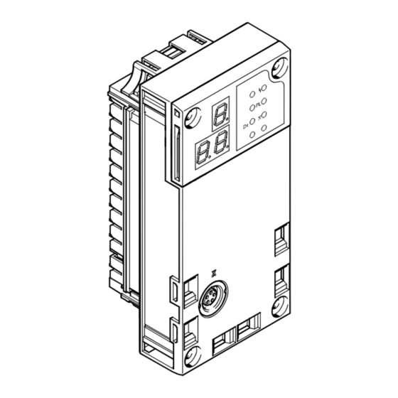
Page 16: Connection And Display Components
– travel at selectable speed with previously configured acceleration in any positions (position control) – application of a defined force with configured force edge [N/s] (force control) with simultaneous speed and position monitoring Festo – P.BE-CPX-CMAX-SYS-EN – en 2017-09b – English... -
Page 17: General Instructions On Use Of The Cmax
• Comply with stroke reduction in accordance with the catalogue specifications. Stroke reduction is 10 ... 35 mm per side – dependent on the cylinder (è www.festo.com/catalogue). Tip: The best positioning behaviour is achieved when only 80 % of the cylinder stroke is used and 10 % remains on each side as reserve. -
Page 18: Mounting And Pneumatic Installation
Malfunctions due to impermissible components The use of components that have not been approved for operation with the CMAX may cause malfunctions. • Use only the special matching components from Festo for setting up and wiring the system. Section 3.2 Section 3.6.3... -
Page 19: Dismantling And Mounting Cmax
2. Unscrew 4 CMAX screws using a TORX screwdriver, size T10. 3. Pull CMAX carefully and without tilting away from the contact rails of the interlinking block. CMAX Contact rails Interlinking block Torx T10 screws Fig. 3.2 Dismantling/mounting the CMAX Festo – P.BE-CPX-CMAX-SYS-EN – en 2017-09b – English... - Page 20 Torx screwdriver size T10 – tightening torque 0.9 ... 1.1 Nm. The parameterisation is saved in the CMAX. After replacing a CMAX, check the parameters and perform commissioning again (è Chapter 5). Observe the instructions in ap pendix A.2. Festo – P.BE-CPX-CMAX-SYS-EN – en 2017-09b – English...
-
Page 21: Mounting Of The Drive And Displacement Encoder
• Fasten the axis to appropriate machine parts that are as rigid as possible. • Connect the drive, guide, displacement encoder and load as free of play as possible and align them flush with each other. Festo – P.BE-CPX-CMAX-SYS-EN – en 2017-09b – English... - Page 22 Too much coupling play leads to: – noise due to knocking on the coupling – increased wear on the coupling – worse operating behaviour Make sure that the coupling play does not exceed 0.05 mm. Festo – P.BE-CPX-CMAX-SYS-EN – en 2017-09b – English...
-
Page 23: Drive, Shock Absorbers And Fixed Stops
• Carry out commissioning again if the fixed stops have been adjusted or components and hoses have been replaced. • Recommendation: Use appropriate external stops, shock absorbers or fixed stops from Festo. Information on mounting the shock absorbers and fixed stops from Festo è Operating instructions for the drive or mounting instructions for the shock absorbers or fixed stops. - Page 24 If the displacement encoder slide leaves the permitted work path, the CMAX generates a corresponding error message. To avoid these error messages: • Limit the positioning range so that the displacement encoder slide is always within the permitted work path. Festo – P.BE-CPX-CMAX-SYS-EN – en 2017-09b – English...
-
Page 25: Load
Note A pneumatic positioning axis should be operated with at least the minimum total load (è www.festo.com/catalogue). If necessary, this minimum mass load must be ensured through the use of an additional weight. The payload present can be specified for each positioning command. The controller setting of the CMAX can thus be adjusted to various loads. - Page 26 300 … 6000 Tab. 3.5 Permitted mass moment of inertia Festo supports calculation of the mass moment of inertia with software for calculation of mass moments of inertia of the second degree for various basic bodies and standard parts from Festo – e.g. push-on flange for DSMI (è www.festo.com/sp, search term: mass moment of inertia (Mass moment of inertia)).
- Page 27 } only vertical mounting position permitted, drive shaft points upward (è Example Fig. 3.3) or downward. – load centre of mass outside the axis of rotation (not recommended): } only vertical mounting position permitted, drive shaft points upward or downward. Festo – P.BE-CPX-CMAX-SYS-EN – en 2017-09b – English...
-
Page 28: Proportional Directional Control Valve Vpwp
450 … 2000 VPWP-6-... 1) With additional reduction from @ 12 to @ 8, with push-in connector QS-12H-8 2) With additional reduction from @ 12 to @ 10, with push-in connector QS-12H-10 Festo – P.BE-CPX-CMAX-SYS-EN – en 2017-09b – English... - Page 29 QS-G1/8-8 QS-G3/8-8 PUN-8x1,25 101 … 350 VPWP-6-... QS-G3/8-10 PUN-10x1,5 > 351 VPWP-8-... QS-G1/4-10 DSMI – (270°) VPWP-4-... QS-G1/8-6 QSM-M5-6 PUN-6x1 – (270°) QS-G1/8-8 QS-G1/8-8 PUN-8x1,25 – (270°) QS-G1/4-8 Tab. 3.6 Drive/valve combinations Festo – P.BE-CPX-CMAX-SYS-EN – en 2017-09b – English...
-
Page 30: Mounting The Vpwp Proportional Directional Control Valve
( 1 ) of the clips grip into the groove of the VPWP. 4. Hang the VPWP on the H-rail. Secure against tipping or slipping by using the H-rail clamping ( 2 ). Festo – P.BE-CPX-CMAX-SYS-EN – en 2017-09b – English... - Page 31 Mounting at right angles to the direction of Proportional directional control valve VPWP movement Not permitted: Mounting in the direction of movement Fig. 3.8 Mounting the VPWP onto moving parts Festo – P.BE-CPX-CMAX-SYS-EN – en 2017-09b – English...
-
Page 32: Mounting The Casm Sensor Interface
The outer fastening screw serves at the same time for earthing ( 1 ). The tightening torque is 2 Nm. Mounting screw (connect earthing) Fig. 3.9 Mounting CASM Mounting on H-rails of size TH35 is possible with mounting kit CP-TS-HS35 (è Fig. 3.10). H-rail Fig. 3.10 Mounting CASM on H-rail Festo – P.BE-CPX-CMAX-SYS-EN – en 2017-09b – English... -
Page 33: Pneumatic Installation
Requirements of the compressed air supply: • Required operating medium: compressed air in accordance with ISO 8573-1:2010 [6:4:4] (è www.festo.com/catalogue as well as brief description on the proportional directional control valve VPWP) • Permissible pressure range: 4 ... 8 bar. -
Page 34: Filter Regulator
Always select tubing between cylinder and VPWP valve to be as short as possible. A tube length of 60 % of the cylinder stroke length is optimal (max. tube length = cylinder stroke length). Festo – P.BE-CPX-CMAX-SYS-EN – en 2017-09b – English... - Page 35 To place the system into a special status in certain applications, an additional pneumatic circuit is re quired, which can be implemented with the VABP sub-base, for example. Notes on this è www.festo.com/catalogue. In addition, the guideline for safety engineering from Festo contains various circuit recommendations (è Appendix A.3).
- Page 36 DNCI Retracted piston Advanced piston DNC with MLO-POT-...-LWG DSMI Anti-clockwise Clockwise (looking at the (looking at the drive shaft) drive shaft) Tab. 3.8 Required direction of movement and tubing with VPWP Festo – P.BE-CPX-CMAX-SYS-EN – en 2017-09b – English...
- Page 37 After installation, the movement test must always be performed. – The resulting positioning times may vary according to the direction of the stroke. Festo – P.BE-CPX-CMAX-SYS-EN – en 2017-09b – English...
-
Page 38: Compressed Air Tubing And Fittings
• Do not use flow control valves or check valves in the air supply lines. • Do not let the tubing project into the travel range. To minimise the effects of bending forces on the positioning behaviour: • Select a sufficiently large energy chain. Festo – P.BE-CPX-CMAX-SYS-EN – en 2017-09b – English... -
Page 39: Electrical Installation
ESD (electrostatic discharge). • Seal unused connections with protective caps. The CMAX power supply is provided via the CPX terminal (è Section 4.5). Festo – P.BE-CPX-CMAX-SYS-EN – en 2017-09b – English... -
Page 40: Earthing
2) Use the supplied self-tapping screw. This ensures electrical contact is established in spite of the anodising layer. 3) Alternatively: Mount the drive on an earthed machine bed. Tab. 4.1 Earthing notes Festo – P.BE-CPX-CMAX-SYS-EN – en 2017-09b – English... -
Page 41: Axis Connection
Straight plug and straight socket KVI-CP-3-GS-GD-5 KVI-CP-3-GS-GD-8 1) Cable between CMAX, VPWP, sensor interface, displacement encoder Tab. 4.3 Connecting cables for the axis string Cabinet through-hole For the cabinet through-feed, we recommend the connecting component KVI-CP-3-SSD. Festo – P.BE-CPX-CMAX-SYS-EN – en 2017-09b – English... -
Page 42: Proportional Directional Control Valve Vpwp
500 mA – Fuse protection Protected against short circuits 1) Temperature switch-off: Maximum short-circuit current (short term) is defined only by the cable and connection resistance. Tab. 4.5 Technical data of connection DO Festo – P.BE-CPX-CMAX-SYS-EN – en 2017-09b – English... -
Page 43: Sensor Interface Casm
Analogue input 0 ... 5 V (INPUT) Earth terminal (FE) The cable screening is connected to the earth terminal of the sensor interface. Tab. 4.8 Pin assignment of connection S2 at the CASM-S-D2-R3 Festo – P.BE-CPX-CMAX-SYS-EN – en 2017-09b – English... -
Page 44: Power Supply
Operating and load voltage are supplied to the CPX terminal through the interlinking blocks or other compon ents of the CPX terminal (è CPX system description). Components of the positioning system are supplied through the CPX-CMAX, which passes on the operating and load voltage of the CPX terminal. The following is supplied... -
Page 45: Power Supply Concept, Formation Of Power Zones
(U EL/SEN • Use a shared power supply unit (è Fig. 4.1). Observe the information on power supply and the required earthing measures in the CPX system description (P.BE-CPX-SYS-...). Festo – P.BE-CPX-CMAX-SYS-EN – en 2017-09b – English... - Page 46 In the 4-pin system supply shown here, all 0 V potentials are also internally connected (è Fig. 4.1). Potential separation between U (0 V) and U (0 V) can be achieved again through an additional EL/SEN power supply for valves to the right of the CMAX (è Fig. 4.2). Festo – P.BE-CPX-CMAX-SYS-EN – en 2017-09b – English...
- Page 47 Activation/Deactivation of the brake/clamping Output VPWP unit by the higher-level PLC Fig. 4.2 Switching off of the load voltage supply of the output at the VPWP together with the valve load supply (example) Festo – P.BE-CPX-CMAX-SYS-EN – en 2017-09b – English...
-
Page 48: Commissioning
• Perform commissioning without bus (pull off bus line) or reset, defined to 0, the PLC output data for the CMAX. With use of a control block (CPX-FEC, CPX-CEC): • Switch the control block to stop! Festo – P.BE-CPX-CMAX-SYS-EN – en 2017-09b – English... -
Page 49: Parameterisation And Commissioning Options
Customised for handling and positioning tasks, Festo has developed an optimised communication pro file, the “Festo Handling and Positioning Profile (FHPP)”. The FHPP enables uniform control and pro gramming for the various bus systems and controllers from Festo. The following is uniformly defined for the user through FHPP: –... - Page 50 CMAX being connected to the PC, such as for preparation of the actual commissioning during design of a system. The Help function for the FCT includes all information for the operation of the Festo Con figuration Tool. The device-specific plug-ins each have their own Help files.
- Page 51 1) V... = Version of the plug-in e.g. V0108 for V1.8 or V0202 for V2.2 Tab. 5.2 Printed information In order to use the printed version in Adobe PDF format, Festo recommends Adobe Reader. Festo – P.BE-CPX-CMAX-SYS-EN – en 2017-09b – English...
-
Page 52: Preparations For Commissioning
The FCT plug-in can read these data out of the CMAX during commissioning. The data do not have to be entered in the FCT project. The data cannot be overwritten by the FCT plug-in. Festo – P.BE-CPX-CMAX-SYS-EN – en 2017-09b – English... - Page 53 Wait for configuration of the axis data. Wait for execution of the movement test. Tab. 5.3 Display during commissioning An overview of the status indicators on the display is shown in segment 6.3.2. Festo – P.BE-CPX-CMAX-SYS-EN – en 2017-09b – English...
-
Page 54: Make Connection To The Pc
Observe the notes and restrictions for operation named in the documentation of the ad apter. Current drives for the adapter NEFC-M12G5-0.3-U1G5 è www.festo.com/sp. Seal the service interface of the CPX node after commissioning with the protective cap supplied. Festo – P.BE-CPX-CMAX-SYS-EN – en 2017-09b – English... -
Page 55: Commissioning With The Fct (Overview)
8. Only for incremental displacement encoder: Perform homing. 9. Carry out identification travel. 10.Carry out test run. After commissioning of the positioning system (è Communication profile description, P.BE-CPX-CMAX- CONTROL-...) perform the following steps: 1. Configure the CPX bus node or control block (CPX-FEC, CPX-CEC). -
Page 56: Notes On Operation
After the power supply is switched on again, with incremental measuring systems, only the positioning commands homing (CPOS.HOM), jogging (CPOS.JOGx) and the movement test are permitted. Other positioning commands result in error E10 (drive is not refer enced è Communication profile description, P.BE-CPX-CMAX-SYS-...). Festo – P.BE-CPX-CMAX-SYS-EN – en 2017-09b – English... -
Page 57: Diagnostics And Error Handling
Diagnostic parameters, diagnostic Communication Through memory, error texts profile description communication CMAX profile 1) Only the groups of the CMAX error messages are displayed in the CPX diagnostics. Tab. 6.1 Diagnostics options Festo – P.BE-CPX-CMAX-SYS-EN – en 2017-09b – English... -
Page 58: Diagnostics Via Leds
Shows error in the display. MC axis X Illuminated green: Positioning job completed (MC = 1). Off: Positioning command active (MC = 0), axis is missing/being installed. Tab. 6.2 LED display in operation after initialisation Festo – P.BE-CPX-CMAX-SYS-EN – en 2017-09b – English... -
Page 59: Cmax-Specific Leds
LED (green) Sequence Status Axis X: MC = 1: Last positioning command completed. Illuminated green Axis X: MC = 0: positioning command active. or axis X is being initialised. LED is off Festo – P.BE-CPX-CMAX-SYS-EN – en 2017-09b – English... -
Page 60: Leds At The Proportional Directional Control Valve Vpwp
LED (yellow) Sequence Status 24 V VPWP load voltage supply is present. illuminated VPWP load voltage supply is not present or error. Error with the CMAX (example): E51, E64 LED is off Festo – P.BE-CPX-CMAX-SYS-EN – en 2017-09b – English... -
Page 61: Leds At The Sensor Interface Casm
No error (normal operating status) – No power supply Error: Initialising via CAN failed. Green Error: Magnet not recognised or incorrect number of magnets. Flashes Flashes red Error: Operating voltage not within permissible green range. Festo – P.BE-CPX-CMAX-SYS-EN – en 2017-09b – English... -
Page 62: Diagnostics Via Display
Error display – example E50: Operating pressure is too low; è Section 6.4.4 Tab. 6.3 Possible error and warning numbers è Section 6.4.4. Possible status displays and addi tional information on the display è Section 6.3.2. Warnings are not shown in the display. Festo – P.BE-CPX-CMAX-SYS-EN – en 2017-09b – English... -
Page 63: Status Display
Positive direction of movement: Starting position = 0 %, position mounting in % of cylinder length Negative direction of movement: Starting position = 99 %, position trailing in % of cylinder length Festo – P.BE-CPX-CMAX-SYS-EN – en 2017-09b – English... - Page 64 Positive direction of movement: Starting position = 0 %, position mounting in % of cylinder length Negative direction of movement: Starting position = 99 %, position trailing in % of cylinder length Festo – P.BE-CPX-CMAX-SYS-EN – en 2017-09b – English...
- Page 65 Positive direction of movement: Starting position = 0 %, position mounting in % of cylinder length Negative direction of movement: Starting position = 99 %, position trailing in % of cylinder length Tab. 6.4 Status information display Festo – P.BE-CPX-CMAX-SYS-EN – en 2017-09b – English...
- Page 66 Programming of the firmware file in the flash memory (program flashes data) Error in programming the firmware file in the Flash memory (Error Program Data) Firmware update successfully completed (Finished Firmware Update) Festo – P.BE-CPX-CMAX-SYS-EN – en 2017-09b – English...
-
Page 67: Faults And Warnings
(SPOS.REF = 0). – FS (system fault): It may no longer be possible to update the I/O data. Switching off/on required. Festo – P.BE-CPX-CMAX-SYS-EN – en 2017-09b – English... -
Page 68: Acknowledgement Of Faults And Warnings - Reset Type
Reset types Acknowledging warnings Warnings do not have to be acknowledged. With rising edge at CPOS.START (new positioning command) or CCON.RESET (provided the cause has been eliminated), SCON.WARN = 0 is set. Festo – P.BE-CPX-CMAX-SYS-EN – en 2017-09b – English... -
Page 69: Illustration Of Cmax Error Numbers In The Cpx Terminal
System error A [System error B] System error B [Error in valve] Error in valve [Controller error] Controller error [Encoder error] Displacement encoder error Tab. 6.8 CPX error numbers and groups of the CMAX Festo – P.BE-CPX-CMAX-SYS-EN – en 2017-09b – English... -
Page 70: Error And Warning Numbers
• Complete the target configuration, e.g. download project again. Cause Drive cannot be enabled because the block download is still active. Measure • End block download. Check and correct the control program (parameterisation). Festo – P.BE-CPX-CMAX-SYS-EN – en 2017-09b – English... - Page 71 Incorrect tubing connection to cylinder and valve. Measure • Check and correct the tubing connection. Movement test not carried out Cause Positioning command without valid movement test. Measure • Perform movement test (recommended) or skip. Festo – P.BE-CPX-CMAX-SYS-EN – en 2017-09b – English...
- Page 72 (CCON.STOP=0). Measure • Remove operation enable. • Release clamping unit. • Correct the sequence when changing from operation enable and clamping unit. Festo – P.BE-CPX-CMAX-SYS-EN – en 2017-09b – English...
- Page 73 DSMI does not support force control. Measure • Correct step enabling condition. Cause The selected step enabling condition is only permissible in a record with force control. Measure • Check and correct record. Festo – P.BE-CPX-CMAX-SYS-EN – en 2017-09b – English...
- Page 74 Message can be parameterised alternatively as a warning (W) or error (F1). Cause Step enabling was not executed. MC was reached before the step enabling condi tion was fulfilled. Measure • Check step enabling condition. • Check the program sequence in the controller. Festo – P.BE-CPX-CMAX-SYS-EN – en 2017-09b – English...
- Page 75 • Check pressure build-up with trace; replace valve if defective. Cause Faulty tubing connection. Measure • Check tubing connection. Cause Valves (additional pneumatic circuit) installed between the valve and cylinder are closed. Measure • Open valves. Festo – P.BE-CPX-CMAX-SYS-EN – en 2017-09b – English...
- Page 76 • Check workpiece; check workpiece position. • Use record sequencing for return travel or stop. Cause Software end positions can be reached in the desired sequence. Measure • Correct software end positions. Festo – P.BE-CPX-CMAX-SYS-EN – en 2017-09b – English...
- Page 77 In the event of record sequencing to force control, the actual speed of the drive is too high at the time of the shift. Measure • Reduce the speed of the previous record, correct the critical speed, deactivate speed monitoring. Festo – P.BE-CPX-CMAX-SYS-EN – en 2017-09b – English...
- Page 78 Communication to the valve and displacement encoder is faulty. Measure • Check cables and components. Cause Communication faulty, e.g. due to impermissible or damaged components on the axis string. Measure • Check installation, replace components. Festo – P.BE-CPX-CMAX-SYS-EN – en 2017-09b – English...
- Page 79 (è I/O data, commissioning mode - byte 4 ... 8). Measure • Check and correct parameter 1 and parameter 2. Cause Movement test was started when a movement test has already been successfully performed. Measure • First reset movement test. Festo – P.BE-CPX-CMAX-SYS-EN – en 2017-09b – English...
- Page 80 • Check load supply for valves (U Controller operating voltage outside the tolerance range Cause Operating voltage < 18 V or overload on the axis string. Measure • Operating voltage supply for electronics/sensors (U EL/SEN Festo – P.BE-CPX-CMAX-SYS-EN – en 2017-09b – English...
- Page 81 • Check parameterisation of the operating pressure. Time-out diagnostic interface: FCT device control was deactivated Cause Connection between PC and CPX node interrupted. Measure • Check cables. Cause Communication breakdown due to FCT Measure • Restore connection. Festo – P.BE-CPX-CMAX-SYS-EN – en 2017-09b – English...
- Page 82 The valve reports a hardware error. Measure • Replace valve. Cause Fault in initialization of the valve. Measure • Replace valve. • Check compatibility of valve and firmware version of the CMAX. Festo – P.BE-CPX-CMAX-SYS-EN – en 2017-09b – English...
- Page 83 • Contact Support. Controller hardware faulty Poff Cause No communication possible with CMAX. Error is only shown on the display. Measure • Switch controller off/on and check whether error occurs again. • Replace CMAX. Festo – P.BE-CPX-CMAX-SYS-EN – en 2017-09b – English...
- Page 84 • Replace displacement encoder/sensor interface. Cause Fault during initialization of the displacement encoder/sensor interface. Measure • Replace displacement encoder/sensor interface. • Check compatibility of the displacement encoder/sensor interface with the firmware version of the CMAX. Festo – P.BE-CPX-CMAX-SYS-EN – en 2017-09b – English...
- Page 85 • If this occurs repeatedly, replace the displacement encoder or sensor interface. Cause Displacement encoder in the electrical end position (potentiometer only). Measure • Move displacement encoder (potentiometer) from the end position. Festo – P.BE-CPX-CMAX-SYS-EN – en 2017-09b – English...
- Page 86 • Switch the power supply off and then on again. If the error is signaled again: • Replace displacement encoder/sensor interface. • Check compatibility of the displacement encoder/sensor interface with the firmware version of the CMAX. Festo – P.BE-CPX-CMAX-SYS-EN – en 2017-09b – English...
-
Page 87: Diagnostic Functions With The Cpx-Mmi
ßà Diag _____________________________________________________ ______________________________________________________ ßà Back Back Error present Error number and description Menu [Diagnostics] Fig. 6.3 Error display with the CPX-MMI Errors of the CMAX cannot be acknowledged with the CPX-MMI. Festo – P.BE-CPX-CMAX-SYS-EN – en 2017-09b – English... -
Page 88: Information On The Cmax (Menu [Module Data] )
Displaying information with the CPX-MMI Module data Description Type code Module code (CPX-specific, for the CMAX: 176) Revision Firmware design (e.g. 2 for version 2.00) Serial No Serial number of the CMAX Festo – P.BE-CPX-CMAX-SYS-EN – en 2017-09b – English... -
Page 89: A Technical Appendix
Tab. A.2 Technical data, voltage supply Positioning system with CMAX Axis string No. of axis strings 1) Undervoltage monitoring, valve and sensor monitoring, storage of the last 100 diagnostic messages, operating hour counter Festo – P.BE-CPX-CMAX-SYS-EN – en 2017-09b – English... - Page 90 – With FCT plug-in CMAX – Through the higher-order controller 1) Undervoltage monitoring, valve and sensor monitoring, storage of the last 100 diagnostic messages, operating hour counter Tab. A.3 Technical data of positioning system Festo – P.BE-CPX-CMAX-SYS-EN – en 2017-09b – English...
- Page 91 Technical appendix Horizontal Vertical With analogue displacement encoder MLO-POT With digital displacement encoder MME-MTS or linear drive DGCI Standard cylinder DNCI Tab. A.4 Repetition accuracy, linear drives Festo – P.BE-CPX-CMAX-SYS-EN – en 2017-09b – English...
-
Page 92: Replacement Of Components
Zero points, position values, software end positions, record table – The reference system can change when the drive or displacement encoder is replaced! • Check reference points. Tab. A.5 Replacement of components Festo – P.BE-CPX-CMAX-SYS-EN – en 2017-09b – English... -
Page 93: Additional Pneumatic Circuits
Festo support portal (è www.festo.com/sp). The sub-base VABP also offers prepared solutions for generating various defined statuses of the drive, which are generated when the load voltage or supply pressure is switched off (è www.festo.com/sp). Festo – P.BE-CPX-CMAX-SYS-EN – en 2017-09b – English... -
Page 94: B Glossary
Homing defines the homing position and thereby the origin of the measuring reference system of the axis. Digital input. From the point of view of the higher-order controller, the CMAX status outputs are module input data (è Communication profile description, P.BE-CPX-CMAX-CONTROL-...). Festo – P.BE-CPX-CMAX-SYS-EN – en 2017-09b – English... - Page 95 Upper software end position: Max. limit position in the positive direction (increasing actual values). Lower software end position: Minimum limit position in the negative direction (decreasing actual values). Tab. B.1 Terms and abbreviations Festo – P.BE-CPX-CMAX-SYS-EN – en 2017-09b – English...
- Page 96 ....... . . Festo – P.BE-CPX-CMAX-SYS-EN – en 2017-09b – English...
- Page 97 ..... . . Warnings ......67, 70 Festo – P.BE-CPX-CMAX-SYS-EN – en 2017-09b – English...
-
Page 98: Index
Copyright: Festo AG & Co. KG Postfach 73726 Esslingen Germany Phone: +49 711 347-0 Fax: +49 711 347-2144 Reproduction, distribution or sale of this document or communica E-mail: tion of its contents to others without express authorization is service_international@festo.com prohibited. Offenders will be liable for damages. All rights re...
Need help?
Do you have a question about the CPX-CMAX and is the answer not in the manual?
Questions and answers