
Related Manuals for Festo CPX-CEC-C1-V3


Summary of Contents for Festo CPX-CEC-C1-V3
- Page 1 Terminal CPX Control block CPX-CEC-C1-V3/-M1-V3/-S1-V3 Description Codesys-Controller 8042601 en 1411c [8042603]...
- Page 3 – Internal CPX-CEC-…-V3 web server: http://<IP address of the device>/cgi-bin/system-about – (Festo AG & CO. KG, D-73726 Esslingen, 2014) Internet: http://www.festo.com E-Mail: service_international@festo.com The reproduction, distribution and utilisation of this document as well as the communication of its contents to others without explicit authorisation is prohibited.
-
Page 4: Table Of Contents
Table of Contents Important information ........................1 1.1 Designated use ..........................1 1.1.1 Safety instructions ......................2 1.1.2 Target group ........................3 1.1.3 Service ........................... 3 1.2 Important user information ......................3 1.2.1 Danger categories ......................3 1.3 Marking special information ......................3 1.3.1 Pictograms ........................ - Page 5 5.3.2 Diagnostic messages on the [Log] tab ................. 61 5.3.3 Diagnosis in the "Scan Festo Devices" dialog .............. 62 5.4 Errors and diagnostic information in SoftMotion (CPX-CEC-M1-V3).......... 63 5.5 Errors and diagnostic information via web server ..............63 5.6 Diagnosis in the user program ....................64 5.7 Diagnosing CANopen.........................
-
Page 7: Important Information
Designated use The Codesys controller CPX-CEC-...-V3 described in this manual is intended exclusively for use in CPX terminals from Festo for installation in a machine or automated system. In combination with a CPX terminal, the CPX-CEC-...-V3 is used for: Controlling pneumatic and electric drives (valves, output modules and motor controllers via CANopen) –... -
Page 8: Safety Instructions
Festo control block CPX-CEC 1.1.1 Safety instructions Protection against dangerous movements Warning The connected actuators are subject to high acceleration forces. Uncontrolled movements can cause collisions which can lead to serious injury. Dangerous movements of connected drives can be caused, for example, by: untidy or faulty wiring, –... -
Page 9: Target Group
1.1.3 Service Contact your local Festo Service partner if you have any technical problems ( www.festo.com). Including the following information and data will make it easier to process support queries: CPX-CEC-...-V3 project ( menu command in Codesys: [File] [Project Archive] [Save/Send Archive], –... -
Page 10: Further Conventions
Festo control block CPX-CEC 1.3.3 Further conventions [File] [New Project...] Menu items are framed in square brackets, for example you can create a new project using the [New Project...] command in the [File] menu. "OK" Names of windows, dialogs and buttons such as "Message Window", "Dearchivate Project", "OK"... -
Page 11: System Overview
Festo control block CPX-CEC System overview Modular valve terminal with integrated controller CPX-CEC-...-V3 Variant Features Codesys target system ID CPX-CEC- Codesys controller with CANopen interface for connecting up to 31 16#103D9C4B C1-V3 CANopen slaves CPX-CEC- Codesys controller with CANopen interface and the Codesys software... -
Page 12: Overview Of Memory Size
Festo control block CPX-CEC Overview of memory size Memory CPX-CEC-...-V3 Global memory and constants (RAM) 192 MB Available flash memory (boot project, project archive, web visualisation, application 16 MB data) Flag memory 28 kB Input 28 kB Output 28 kB 2.3.1... -
Page 13: Libraries
For easy networking of controllers via EasyIP. Festo_Motion_3.library For configuring motor controllers from Festo (e.g. CMMP-AS). Festo_FHPPMAX_3.library Festo profile FHPPMAX Festo_CPX-CMAX_3.library For controlling and parameterising the Festo axis controller CPX- CMAX. Festo_CVE_3.library For actuating motor controllers that support the CVE protocol from Festo (e.g. CMMO-ST). Festo_CameraControl_3.library For accessing the Compact Vision System SBO...-Q. -
Page 14: Operating Modes Of The Cpx Terminal With Codesys Controller
Festo control block CPX-CEC Operating modes of the CPX terminal with Codesys controller The Codesys controller can be operated in different modes, depending on the requirement: Standalone – Remote Controller Ethernet – Remote Controller Fieldbus (fieldbus node required) – The individual operating modes are described briefly below: 2.5.1... -
Page 15: Remote Controller Fieldbus Operating Mode
Festo control block CPX-CEC 2.5.3 Remote Controller Fieldbus operating mode 1 CPX-CEC-...-V3 for communication via the fieldbus node connected to the fieldbus 2 CPX fieldbus node, in this case CPX-FB13 3 CPX terminal controlled by CPX-CEC-...-V3 Remote Controller Fieldbus operating mode (fieldbus node required) -
Page 16: Installation
Festo control block CPX-CEC Installation General information Caution Risk of injury due to electric shock. • Always switch off the power supply before mounting or removing CPX modules. Note The controller CPX-CEC-...-V3 contains electrostatically sensitive components. • Therefore do not touch any contacts. -
Page 17: Mounting And Removal
The device is mounted in a manifold sub-base of the CPX terminal: 1 CPX-CEC-...-V3 2 Manifold sub-base 3 Contact rails 4 Screws (4) Figure: Mounting/removing the device (in this case CPX-CEC-C1-V3/-M1-V3) 3.2.1 Removal Note • Never remove the CPX-CEC-...-V3 while still wired. -
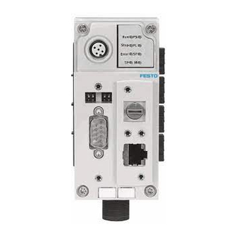
Page 18: Connection And Display Components
Festo control block CPX-CEC Connection and display components 1 Status LEDs 5 DIL switch 1 ( section DIL switches) 2 RUN/STOP rotary switch 6 DIL switch 2 ( section DIL switches) 3 Ethernet interface (10/100BaseT, RJ45) 7 Connection for handheld CPX-MMI... -
Page 19: Setting The Switches On The Codesys Controller
Festo control block CPX-CEC Setting the switches on the Codesys controller 3.4.1 RUN/STOP rotary switch Note The RUN/STOP rotary switch is set in the factory to position "1". • Set the RUN/STOP rotary switch to position "0" (STOP) during installation to prevent the program being started either automatically after the voltage is switched on or inadvertently by a commissioning technician. -
Page 20: Interfaces
You will need a patch or crossover cable to connect your Codesys controller to a network or PC. The interface automatically detects which cable is connected and automatically switches the signals. Note • Use the RJ45 plug from Festo to ensure protection to IP65/IP67 ( section Ensuring protection to IP65/IP67): FBS-RJ45-8-GS –... -
Page 21: Communication Interfaces
The plug housing must be connected to FE. 1) CAN Ground (optional), pin 6, on the CPX-CEC-C1-V3/-M1-V3 must not be used if a motor controller with an external power supply is connected. Table: Pin allocation of the CANopen interface (CPX-CEC-C1-V3/-M1-V3) The CANopen interface does not supply the connected CAN bus slaves with voltage. - Page 22 (T-TAP function). Note The clamp strap in the CAN bus plug from Festo is connected internally only capacitively with the metallic housing of the sub-D plug. This is to prevent equalising currents flowing through the screen of the CAN bus.
-
Page 23: Rs232 Interface (Cpx-Cec-S1-V3)
Festo control block CPX-CEC 3.5.3 RS232 interface (CPX-CEC-S1-V3) The RS232 interface enables external devices to be connected to the CPX-CEC-S1-V3. When using external devices, data communication must be programmed by the user. Socket Signal Comment n. c. Not connected Received data Transmitted data n. -
Page 24: Connecting An Operator Unit Cdpx
Festo control block CPX-CEC Connecting an operator unit CDPX The operator unit CDPX is a display for executing and monitoring automation tasks at the field level. • Refer to the accompanying user documentation when installing the device. Figure: CPX-CEC-...-V3 with operator unit CDPX •... -
Page 25: Connecting A Handheld Cpx-Mmi
Festo control block CPX-CEC Connecting a handheld CPX-MMI The 5-pin M12 socket is used for connecting a CPX-MMI for fast preliminary commissioning, diagnosis or parameterisation. Figure: CPX terminal with handheld CPX-MMI The connection to the CPX-MMI is interrupted while downloading a program if parameters were changed via Codesys. -
Page 26: Commissioning
– Information on installation and system requirements for the software packages is included in the relevant user documentation. 4.2.2 Software CODESYS V3 pbF ( www.festo.com/sp) – CPX-CEC package compatible with firmware – 4.2.3 Important documentation for the controller hardware and software... -
Page 27: Getting Started
Festo control block CPX-CEC Getting started • Launch Codesys. You will find the program on your Windows PC in the Start menu directory [Programs] [Festo Software] [CODESYS V3]. 4.4.1 Creating a project • Create a new project ([File] [New Project...]), enter a name and the storage location and confirm your entries by clicking "OK". - Page 28 Festo control block CPX-CEC Select the relevant interfaces. Figure: "New Project" dialog – selecting the interfaces Options not supported by the respective device are inactive (shown in grey) and cannot be selected. The Codesys program window opens with the newly created project.
-
Page 29: Finding Devices
If these criteria are not met, the device must be detected using the Festo scan program ( section Scan Festo Devices). The network settings for the device can be read out in the scan program and changed to suit your company network. -
Page 30: Manually Adding A Device
Festo control block CPX-CEC 4.4.4 Manually adding a device You can also manually add a known device as an alternative to automatic selection. Highlight the local gateway. Click the "Add device..." button. Figure: "Add device" dialog Enter the name, node address or IP address of the device to be connected in the "Add device" dialog and confirm your entries by clicking "OK". -
Page 31: Setting The Communication Channel
The currently active path is shown in bold in the list and "(active)" is appended to the name. Figure: Activated device Scan Festo Devices To launch the scan program "Scan Festo Devices": Click the icon in the toolbar of the Codesys program window. Click the menu command [Online] [Scan Festo Devices]. -
Page 32: Changing Network Settings
If necessary, change the settings for the subnet mask, standard gateway and DNS server. Transfer the changes to the device. To do this, click "OK". Wait until the device has successfully completed the switch-on process ("Run" or "Stop" status LED lights up). Close the "Scan Festo Devices" scan program. -
Page 33: Configuring The Cpx System
Festo control block CPX-CEC Configuring the CPX system Click the "CPX_System" node in the "Devices" window. Figure: Configuring the CPX modules Configure the system by entering the order code ( section Configuration by entering the order code), automatically ( section Automatically reading in the configuration) or manually ( section Manual configuration). -
Page 34: Automatically Reading In The Configuration
Festo control block CPX-CEC 4.6.2 Automatically reading in the configuration Prerequisite: The communication channel must be set ( section Setting the communication channel). Double-click the "CPX_System" node in the "Devices" window. Select the "Actual configuration" function on the [Module Configuration] tab. - Page 35 Festo control block CPX-CEC Select the appropriate CPX modules from the list. Figure: Adding a CPX module, in this case CPX module 4AI-I The inputs and outputs are automatically addressed (preset in the device on delivery). At least 1 byte of inputs or outputs is reserved for each module. The rotary switch of the CPX-CEC-…-V3, for example, only occupies 4 bits of inputs, but 1 byte is reserved.
- Page 36 Festo control block CPX-CEC Figure: Changing the I/O address manually • Check the "Always update variables" box.
-
Page 37: Parameterisation Of The Cpx Terminal
Festo control block CPX-CEC 4.6.4 Parameterisation of the CPX terminal The CPX terminal is supplied from the factory with preset parameters. If required, you can set the reaction of the CPX terminal as well as the reaction of individual modules and channels through parameterisation. -
Page 38: Cpx System Settings
Festo control block CPX-CEC CPX system settings • Select "CPX_System" in the device tree. Figure: CPX_System, shown as a node in the device tree The [Module Configuration] tab contains information about the settings for the CPX system and the diagnostic memory (trace parameters). - Page 39 Festo control block CPX-CEC The following options can be set: Keep current values – Set all outputs to default – Execute program – Figure: PLC system settings The setting of specific values in stop mode can therefore be achieved via the "Execute program" option.
-
Page 40: Parameterising A Cpx Module
Festo control block CPX-CEC Parameterising a CPX module The parameters cannot be changed in online mode. Select a module in the device tree. Figure: CPX module selection The [Module Configuration] tab contains information about the settings for the CPX module. - Page 41 Generate a boot project if required so that the parameters will be activated in the module after a restart. The [Festo CPX I/O Mapping] tab contains details of the I/O information for the CPX module. Figure: Festo CPX I/O Mapping Note •...
- Page 42 Festo control block CPX-CEC Module errors are displayed on the [Status] tab in online mode. Figure: CPX module status Information about the module available electronically is displayed on the [Information] tab. Figure: CPX module information...
-
Page 43: Parameterising Via The Handheld Cpx-Mmi
Festo control block CPX-CEC Parameterising via the handheld CPX-MMI The parameters of the CPX terminal can also be read and modified via a connected handheld type CPX- MMI. Transferring the parameter settings to the CPX modules Note Parameterisations via CPX-MMI are only saved locally in the CPX terminal and are lost when –... -
Page 44: Configuring A Canopen Slave
Festo control block CPX-CEC 4.11 Configuring a CANopen slave Connecting via CANopen requires an appropriate baud rate. The [CANbus] tab for setting the baud rate is opened by double-clicking the "CAN" branch in the Codesys device window. 4.11.1 Adding a CANopen slave Highlight the CANopen_Manager branch in the Codesys device window. - Page 45 Festo control block CPX-CEC Select a CANopen slave in the device table and highlight it. Example: FB14 Confirm the selection by clicking the "Add Device" button. If necessary, repeat steps 3 and 4 to add further devices (max. number of CANopen slaves: 32).
-
Page 46: Integrating Cpv Terminals
Festo control block CPX-CEC This option is activated by default for the CPX-CEC-…-V3 under CODESYS V3 pbF. 10. If necessary, check the "Autoconfig PDO Mapping" box on the "CANopen Remote Device" tab in the editing window. This setting executes automatic configuration if the CANopen slave supports sub-modules. -
Page 47: Configuring Softmotion (Cpx-Cec-M1-V3 Only)
Festo control block CPX-CEC 4.12 Configuring SoftMotion (CPX-CEC-M1-V3 only) The Codesys software package SoftMotion is available as an extension for the controller CPX-CEC-M1- V3. It allows coordinated multi-axis movements with a CPX terminal. Specific CPX-CEC-M1-V3 controller features are produced in accordance with the CPX system properties. -
Page 48: Carrying Out Configuration
Festo control block CPX-CEC 4.12.5 Carrying out configuration In the task configuration, open the task responsible for executing the function blocks that generate the movement. In the following steps, the task containing the function blocks that generate the movement is called "MotionTask". - Page 49 Festo control block CPX-CEC Figure: Configuring the CANopen_Manager Set "MotionTask" as the bus cycle time on the [CANopen I/O Mapping] tab. Figure: Configuring the bus cycle task 10. Add SoftMotion drives to the CANopen_Manager (e.g. CMMP_AS_C2_3A_M3_SoftMotion). Virtual drives can be added to the "SoftMotion General Axis Pool".
- Page 50 Festo control block CPX-CEC 11. Set the node IDs of the drives as appropriate to the FCT configuration. Figure: Configuring the node ID 12. Configure the basic parameters of the individual SoftMotion drives on the [SoftMotion Drive: Basic] tab. Figure: Configuring the basic parameters 13.
-
Page 51: Configuring Modbus Tcp
Festo control block CPX-CEC 4.13 Configuring Modbus TCP The controller CPX-CEC-…-V3 supports Modbus TCP Client as well as Modbus TCP Master. Operation with Modbus TCP Master is restricted to 8 simultaneously usable channels. Detailed information on Modbus TCP can be found in the online Help for Codesys. - Page 52 Festo control block CPX-CEC Figure: Device window - selecting "Modbus TCP Master" in the "Ethernet" branch Highlight the new "Modbus TCP Master" branch and add the "Modbus TCP Slave" module using the context menu. Repeat this process for the other Modbus TCP slaves.
- Page 53 Festo control block CPX-CEC Highlight one of the "Modbus TCP Slave" branches. Several tabs for parameterising the selected "Modbus TCP Slave" are displayed in the workspace. Figure: Workspace for "Modbus TCP Slave" (parameters) 10. Enter the IP address for the Modbus TCP slave.
- Page 54 Festo control block CPX-CEC Figure: Settings on channel 1 Figure: Settings on channel 2...
- Page 55 Festo control block CPX-CEC This gives the master an I/O map for the slave. Figure: [Modbus TCP Slave I/O Mapping] tab If the timeout option is activated and if this has a value greater than zero, the holding register values (%IW) are automatically reset after this time WITHOUT further remote access to the...
-
Page 56: Cpx-Cec
Festo control block CPX-CEC 4.13.2 CPX-CEC-…-V3 as Modbus TCP slave device Highlight the "Ethernet" branch and add the module "Modbus TCP Slave Device" via the context menu. Figure: Selecting "Modbus TCP Slave" in the "Ethernet" branch Highlight the branch of the device being parameterised as a "Modbus TCP Slave Device". -
Page 57: Online Mode
Festo control block CPX-CEC 4.14 Online mode Caution Risk of injury due to uncontrolled movements of the connected actuators. • Test projects and programs without active actuators initially. A configured project including program (CPX-CEC-…-V3 application) is to be transferred to the CPX-CEC- …-V3. - Page 58 Festo control block CPX-CEC Once online mode is active, the connection to the CPX-CEC-...-V3 as well as the application are highlighted in green in the device window. The CPX-CEC-...-V3 is online, the application is not started (not running), the "Run" status LED lights up yellow.
-
Page 59: Starting And Monitoring The Application
Festo control block CPX-CEC 4.14.2 Starting and monitoring the application The application can be started on the CPX-CEC-...-V3 if error-free data has been transferred. Use one of the following commands to start the application: Click the icon in the toolbar of the Codesys program window –... -
Page 60: Forcing
Festo control block CPX-CEC 4.15 Forcing Forcing allows you to manipulate input and output signals. Actual input signals or status changes by program are ignored and replaced by the force values. Warning High acceleration forces of the connected actuators. Uncontrolled movements of the actuators can cause collisions which can lead to serious injury. -
Page 61: Plc Shell
Festo control block CPX-CEC 4.16 PLC shell The PLC shell is a text-based controller monitor (terminal). Commands for requesting certain information from the controller are entered in an input line and sent to the controller as a string. The returned response string is displayed in a results window in the browser. -
Page 62: Diagnosis
In the diagnostic node ( section Diagnostic messages in PLC diagnosis) – On the Log tab using logger: FestoLog ( section Diagnostic messages on the – [Log] tab) In the Scan Festo Devices dialog ( section Diagnosis in the "Scan Festo – Devices" dialog) Web server Shows system diagnosis... -
Page 63: Status Leds
Festo control block CPX-CEC Status LEDs The LEDs of the CPX-CEC-...-V3 indicate the operating condition of the device. 1 RUN 2 PS PLC status: started (green) Electronics supply, sensor supply (green) STOP PLC status: stopped (yellow) Load supply (green) ERROR PLC runtime error (red) - Page 64 Festo control block CPX-CEC Sequence Meaning Error handling • ERROR PLC program Read out error code via (PLC error handheld or Codesys runtime Error number: Lights up error) CPX error No error – Does not light up Ethernet – (Ethernet...
- Page 65 Festo control block CPX-CEC Sequence Meaning Error handling PL (power No error. Load – load) voltage present Lights up green • Load voltage at Eliminate undervoltage the system supply or Flashes additional supply green outside the tolerance range • SF (system Minor error ...
-
Page 66: Online Diagnosis In The Controller Configuration
Festo control block CPX-CEC Online diagnosis in the controller configuration 5.3.1 Diagnostic messages in PLC diagnosis Diagnostic information is recorded and displayed centrally in PLC diagnosis. • Select "PLC_Diagnosis" in the device tree. Figure: Selecting "PLC_Diagnosis" Figure: PLC_Diagnosis... -
Page 67: Diagnostic Messages On The [Log] Tab
Festo control block CPX-CEC The "PLC-Diagnosis" dialog provides the following functions: Updating the diagnostic information – Graphical overview of PLC diagnosis – Exporting all messages to a CSV file – Selection filter for displaying the diagnostic messages: – Error –... -
Page 68: Diagnosis In The "Scan Festo Devices" Dialog
5.3.3 Diagnosis in the "Scan Festo Devices" dialog Diagnostic information is called up in the "Scan Festo Devices" dialog in the context menu of the selected Festo device using the "Diagnosis" function. Figure: Calling up "Diagnosis" in the "Scan Festo Devices" dialog... -
Page 69: Errors And Diagnostic Information In Softmotion (Cpx-Cec-M1-V3)
[Programming Interface] [SoftMotion Libraries] [SM3] [Basic] [Data Types] [Error] [SMC_ERROR]. Errors and diagnostic information via web server Diagnostic information is called up in the "Scan Festo Devices" dialog in the context menu of the selected Festo device using the "Homepage" function. -
Page 70: Diagnosis In The User Program
Select [System] [Diagnosis] to display the diagnostic information for the CPX modules. Figure: Diagnosis on the homepage of the CPX-CEC module Diagnosis in the user program The following Festo libraries can be used for diagnosis in the user program: Festo_General_3: General device diagnosis. –... -
Page 71: Application And Programming Instructions
Festo control block CPX-CEC Application and programming instructions I/O update The runtime system of the CPX-CEC-...-V3 operates with a task-dependent I/O update which only updates outputs that are assigned to a task. Codesys automatically detects which outputs a task is using. -
Page 72: Using Canopen_Manager
Festo control block CPX-CEC Using CANopen_Manager A start telegram is sent to each CANopen station as standard. The "NMT Start All" option on the [CANopen_Manager] tab starts all slaves simultaneously. Figure: Selecting CANopen_Manager Figure: "NMT Start All" option Note The command "NMT Start All" is not executed while optional slaves are not yet ready to start. In this situation, the CANopen Manager starts each slave individually. -
Page 73: Node Guarding
Festo control block CPX-CEC Node guarding Node guarding telegrams can be interrupted in stop mode when using the CAN interface. Open the [PLC settings] tab in the CPX-CEC-…-V3. Check the "Update IO while in stop" box. Figure: PLC settings for CPX-CEC... -
Page 74: Technical Appendix
Festo control block CPX-CEC Technical appendix Technical data Feature Description CPX system manual P.BE-CPX-SYS-... ( www.festo.com/sp) General technical data for the CPX terminal Total number of axes: CPX-CEC-C1-V3 – CPX-CEC-M1-V3 – CPU data 800 MHz processor Configuration support Codesys V3... - Page 75 Festo control block CPX-CEC Feature Description Data interface (CPX-CEC-S1- Type RS232 interface – Connection technology Socket, Sub-D, 9-pin – Data transmission speed 9.6 ... 230.4 kbps – Electrical isolation – Max. line length 30 m – Degree of protection IP65/IP67 (only in combination with plugs and covers with protection to...
-
Page 76: Glossary
(CNC machines) or the devices (controllers, computers) used for them. CODESYS V3 pbF CODESYS V3 provided by Festo allows the configuration, commissioning and programming of different Festo components and devices. It is called "Codesys" for short in this online Help/manual. Codesys target system ID Target system ID. - Page 77 Provides the connection to specific field buses. Transmits control signals to the connected modules and monitors their ability to function. Festo Field Device Tool. FHPP Festo Handling and Positioning Profile; standardised fieldbus data profile for positioning controllers from Festo. Handheld CPX-MMI Handheld programmer for commissioning and service purposes.
- Page 78 Festo control block CPX-CEC SoftMotion Motion functionality integrated in the Codesys programming and runtime system. The following motion control models are offered as modules: Single/multi-axis motions with PLCopen motion modules – 2.5-D CNC controller. – PLC/IPC Programmable logic controller/industrial PC.
Need help?
Do you have a question about the CPX-CEC-C1-V3 and is the answer not in the manual?
Questions and answers