
Related Manuals for Festo CPX-E-CEC EP Series


Summary of Contents for Festo CPX-E-CEC EP Series
- Page 1 CPX-E-CEC-...-EP Controller Description | Function, Parameterisation 8126541 8126541 2020-01a [8126543]...
- Page 2 Translation of the original instructions ® ® ® ® CODESYS , EtherCAT , EtherNet/IP , MODBUS are registered trademarks of the respective trade- mark owners in certain countries. Festo — CPX-E-CEC-...-EP — 2020-01a...
-
Page 3: Table Of Contents
Service Menu......................25 Connecting components....................26 2.6.1 Operating voltage supply..................26 2.6.2 Network connections....................26 2.6.3 Memory card slot....................27 2.6.4 USB interface [USB]....................27 Additional functions..................... 28 2.7.1 FTP server....................... 28 2.7.2 Web server......................28 2.7.3 Temperature sensor....................28 Festo — CPX-E-CEC-...-EP — 2020-01a... - Page 4 Specifying the operating mode for diagnostic messages........36 2.8.2.4 Emergency message....................36 2.8.3 Diagnostics via web server..................39 2.8.4 Diagnostics via the CDSB operator unit..............41 Parameterisation......................41 Technical Data......................43 General Technical Data....................43 Technical Data UL/CSA Certification................44 Festo — CPX-E-CEC-...-EP — 2020-01a...
-
Page 5: About This Document
Instruction manual for operator unit CDSB General functions of the operator unit Tab. 1 Further applicable documents All available documents for the product è www.festo.com/pk. Target group This document is intended for qualified personnel. Experience with electrical control systems is required in order to understand this documentation. -
Page 6: Product Labelling
About this Document Appropriate software for determining the product version can be found in the Festo Support Portal è www.festo.com/sp. Information on using the software can be found in the integrated Help function. There may be an updated version of this document for these or later product versions. -
Page 7: Ul/Csa Certification
• Virtual private Network (VPN) • Security at physical access level (port security) For additional information è Guidelines and standards for security in information technology, e. g. IEC 62443, ISO/IEC 27001. An access password only protects against unintentional modification. Festo — CPX-E-CEC-...-EP — 2020-01a... -
Page 8: Function
The product supports crossover detection (auto MDI/MDI-X), which means that there is the option of using patch cables or crossover cables. When using patch cables and crossover cables in the network, crossover detection must be activated in the higher-order controller. Festo — CPX-E-CEC-...-EP — 2020-01a... -
Page 9: Internal Address Assignment
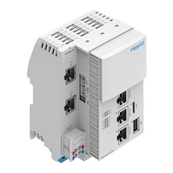
10 EtherNet/IP network connection Port 2 [XF2] 11 Linking element 12 EtherNet/IP network connection Port 1 [XF1] 13 Rotary switch for setting the 4th octet of the IP address for the EtherNet/IP network connection Fig. 2 Product design Festo — CPX-E-CEC-...-EP — 2020-01a... -
Page 10: Display Components
A CODESYS boot application cannot be started. Run Stop A project that is running will be stopped. è Stop Run A project that was stopped using the run/stop switch will be continued. è Tab. 6 Run/stop switch Festo — CPX-E-CEC-...-EP — 2020-01a... -
Page 11: Rotary Switch
For invalid values, the internal configuration is used. Factory setting 192.168.1.1 (DHCP active) The DIL switches are reserved and have no function. Tab. 7 Rotary switch Changes to the rotary switches only take effect following a restart of the module. Festo — CPX-E-CEC-...-EP — 2020-01a... -
Page 12: Operator Unit Cdsb (Optional)
Operator Unit CDSB (Optional) 2.5.3.1 Overview The operator unit CDSB is available as an optional accessoryè www.festo.com/catalogue. Fig. 5 Operator unit CDSB As delivered, the interface to the controller CPX-E-CEC-...-EP is closed with a cover. The cover must be removed before plugging in the operator unit CDSB. -
Page 13: Touch-Sensitive Areas And Unit-Specific Symbols
If an error is present: the corresponding symbol appears in the header and when displaying the mes- sage. Symbols Function/description Process successfully executed In process Finished (ready for operation) Tab. 10 Unit-specific symbols for the status display Festo — CPX-E-CEC-...-EP — 2020-01a... -
Page 14: Menu Structure And Main Menu
(example shown is "Service" CPX-E-CEC-...-PN) "Brightness" General menus and information “Instruction manual for operator for the operator unit CDSB unit CDSB” "Orientation" 1.1 Further applicable è "Calibration" documents "CDSB Info" Tab. 11 Main menu for the operator unit CDSB Festo — CPX-E-CEC-...-EP — 2020-01a... -
Page 15: Unit-Specific Menus (Overview)
Menu for setting the delay for 2.5.3.13 Time setting menu è return to the main menu if inact- "Service" "Control" Menu for unit control 2.5.3.14 Service Menu è (Selection: Stop, Reset, Run) Tab. 12 Overview of the unit-specific menus Festo — CPX-E-CEC-...-EP — 2020-01a... -
Page 16: Unit-Specific Menus (1St Level)
CPX-E-CEC-...-EP: – "Diagnosis" – "Bus Systems" – "Settings" – "Service" The user can switch between the available menus/screens within the menu level by touching the "<" and ">" symbols. Fig. 6 Unit-specific menus (1st level) Festo — CPX-E-CEC-...-EP — 2020-01a... -
Page 17: Status Display Menu
The"Diagnosis" "State" menu displays the current status of the controller CPX-E-CEC-...-EP, e.g. "Ready" or "no project". After switching on the supply voltage to the controller, the operator unit CDSB automatically switches to the status display and displays the current status as start screen. Fig. 7 Menu"Diagnosis""State" Festo — CPX-E-CEC-...-EP — 2020-01a... -
Page 18: Diagnostic Messages Menu
Function 2.5.3.7 Diagnostic messages menu The"Diagnosis" "Messages" menu displays all active messages. Fig. 8 Menu"Diagnosis""Messages" Festo — CPX-E-CEC-...-EP — 2020-01a... -
Page 19: Unit Information Menu
The "Diagnosis" "Device Info" menu displays information about the controller CPX-E-CEC-...-EP and has the following submenus/screens: "Device Name", "Unique Id", "iTAC Number", "Product Key", "Bootloader Ver", "Firmware Ver" and "Revision". Fig. 9 Menu "Diagnosis""Device Info" Festo — CPX-E-CEC-...-EP — 2020-01a... -
Page 20: Network Menu
Function 2.5.3.9 Network menu The "Diagnosis" "Network" menu displays the network configuration. The "Network" menu has the following submenus/screens: – "MAC" – "IP-Address " – "Subnetmask " – "Gateway" Fig. 10 Menu "Diagnosis""Network" Festo — CPX-E-CEC-...-EP — 2020-01a... -
Page 21: Ie Device Menu
IE device menu The "Diagnosis" "IE Device" menu has the following submenus/screens for displaying Industrial Eth- ernet device information (EtherNet/IP device): – "IE Device Typ" – "IE Firmware V." – "IE HW-Revision" Fig. 11 Menu "Diagnosis""IE Device" Festo — CPX-E-CEC-...-EP — 2020-01a... -
Page 22: Bus Systems Menu
Function 2.5.3.11 Bus systems menu The "Bus Systems" "System Bus" menu displays all modules connected to the system bus. Fig. 12 Menu "Bus Systems""System Bus" Festo — CPX-E-CEC-...-EP — 2020-01a... -
Page 23: Network Settings Menu
Function 2.5.3.12 Network settings menu The IP configuration for the standard Ethernet interface of the controller CPX-E-CEC-...-EP can be manually set and modified using the "Settings" "Network" menu. Fig. 13 Menu "Settings""Network" Festo — CPX-E-CEC-...-EP — 2020-01a... -
Page 24: Time Setting Menu
The following can be set using the "Settings" "Timeout" menu The period after which the start screen is displayed or the display returns from the CDSB menu to the main menu following inactivity. Possible value range: 5 … 600 seconds Fig. 14 Menu "Settings""Timeout" Festo — CPX-E-CEC-...-EP — 2020-01a... -
Page 25: Service Menu
The error message "No project loaded" is briefly displayed. The higher-level menu "Control" is then displayed. – When activating "Abort": The selected command is cancelled and the higher-level menu "Control" is displayed. Fig. 15 Menu "Service""Control" Festo — CPX-E-CEC-...-EP — 2020-01a... -
Page 26: Connecting Components
Ethernet interfaces for the connection of a programming device, PC or operating unit CDPX [ETH2] [EC] EtherCAT Master Tab. 15 Network connections The network connections ETH1 and ETH2 are connected to the controller via a switch. Festo — CPX-E-CEC-...-EP — 2020-01a... -
Page 27: Memory Card Slot
Maximum memory size: 32 GB – Formatting: FAT32 (one partition only) Use only memory cards that are sold by Festo as accessories for the product è www.festo.com/catalogue. Festo does not provide any warranty for the use of other memory cards. The memory card slot is only intended for user-monitored operation. -
Page 28: Additional Functions
The controller has a real-time clock, which can be set or read with the aid of CODESYS function blocks: – for run-time of CODESYS projects è CODESYS SysTimeRtc library – in online mode with the aid of the PLC shell è CODESYS V3 Festo — CPX-E-CEC-...-EP — 2020-01a... -
Page 29: Diagnostics Options
Further diagnostic options using CODESYS are explained in the online help for the CPX-E-CEC control- ler. 2.8.1 LED indicators The module- and network-specific LED displays are described below. The system-specific LED indicators are described in the documents for the automation system CPX-E è 1.1 Further applicable documents. Festo — CPX-E-CEC-...-EP — 2020-01a... - Page 30 Network connection established Status “Link” – Network connection established Status “Activity” Flashing No network connection Check network connection. Tab. 18 Ethernet interfaces [LAETH1] [LAETH2] EtherCAT interface [LA EC] Meaning Remedy (green) – Network connection established Status “Link” Festo — CPX-E-CEC-...-EP — 2020-01a...
- Page 31 Status “Link” – Network connection established Status “Activity” Flashing No network connection Check network connection. Tab. 20 Connection status [XF1], [XF2] Module status [MS] Meaning Remedy (green, red, orange) – Normal operating status Lit up green Festo — CPX-E-CEC-...-EP — 2020-01a...
- Page 32 – The automation system CPX-E is in self-test mode. Flashing altern- ately red/gre- – Bootloader Lit up orange No logic power supply to the network inter- Check logic supply. face Tab. 21 Module status [MS] Festo — CPX-E-CEC-...-EP — 2020-01a...
- Page 33 Network-specific LED indicators è Lit up orange The automation system CPX-E is offline. Check network connection. No IP address assigned or no IP address Check IP addressing settings. received from DHCP server. Tab. 22 Network status [NS] Festo — CPX-E-CEC-...-EP — 2020-01a...
-
Page 34: Diagnostics Via Ethercat
To simplify diagnostics evaluation, the controller offers the option of having the presence of a new dia- gnostic message evaluated by the process data. To do this, the object “New message available” can optionally be mapped to the process data. This is done via diagnostics object 0x10F3 (sub-index 4). Festo — CPX-E-CEC-...-EP — 2020-01a... -
Page 35: Sample Diagnostic Message
Tab. 25 Values of diagnostic message The text IDs 3700 … 37FF correspond with the CPX error numbers (0 … 255). Further information is available in the "Description of the automation system CPX-E" è 1.1 Further applicable documents. Festo — CPX-E-CEC-...-EP — 2020-01a... -
Page 36: Specifying The Operating Mode For Diagnostic Messages
The EtherCAT devices send an emergency message when an error occurs. The emergency message can be activated and deactivated using the diagnostics object 0x10F3 (sub-index 5, bit 0). Emergency message Value of bit 0 Deactivate Activate Tab. 28 Deactivating/activating emergency message Festo — CPX-E-CEC-...-EP — 2020-01a... - Page 37 Load voltage failure at output module or input module – – Communication error Node guard, heartbeat, fieldbus-specific only – – 5 6 … Manufacturer specific Wire break, other error Tab. 31 Emergency message – error register (byte 2) Festo — CPX-E-CEC-...-EP — 2020-01a...
- Page 38 Additional error informa- For example: … tion – Node ID with heartbeat error (which participant has caused the timeout?) – Channel number of the first channel with error Tab. 35 Emergency message – additional error information (byte 7) Festo — CPX-E-CEC-...-EP — 2020-01a...
-
Page 39: Diagnostics Via Web Server
IP address of controller: 192.168.0.1 (factory setting) The IP address of the controller can be read from the controller using suitable software è CODESYS – scan Festo devices or è Festo Field Device Tool (FFT). Fig. 16 Web server Festo — CPX-E-CEC-...-EP — 2020-01a... - Page 40 CI (Communication Interface) – Execute commands from the CPX-E-CEC System – Diagnostics information – Information about the controller and current parameters – Information about the controller manufacturer CODESYS – Information about the CODESYS licence for the controller Festo — CPX-E-CEC-...-EP — 2020-01a...
-
Page 41: Diagnostics Via The Cdsb Operator Unit
– System bus parameters You can find a detailed description of the individual parameters in the "Description of the automation system CPX-E" and in the descriptions of the corresponding modules è 1.1 Further applicable documents. Festo — CPX-E-CEC-...-EP — 2020-01a... - Page 42 Detailed information on parameterisation can be found in the online help for CODESYS V3. • Observe the notes on installing CODESYS V3 in the "Instruction manual for the automation system CPX-E" è 1.1 Further applicable documents. Festo — CPX-E-CEC-...-EP — 2020-01a...
-
Page 43: Technical Data
222/102 CPX-E-CEC-M1-EP 222/103 Module identification CPX-E-CEC-C1-EP E-CEC-C1-EP CPX-E-CEC-M1-EP E-CEC-M1-EP 1) including cover, not including linking element 2) Including linking element 3) for non-conforming technical data see UL operating conditions table Tab. 38 General Technical Data Festo — CPX-E-CEC-...-EP — 2020-01a... -
Page 44: Technical Data Ul/Csa Certification
3) required for maximum connection length between network participants Tab. 40 Network-specific Data Technical Data UL/CSA Certification Ambient conditions UL/CSA Pollution degree Installation site for indoor use only Max. installation height [m] 2000 Tab. 41 Ambient Conditions UL/CSA Festo — CPX-E-CEC-...-EP — 2020-01a... - Page 45 EL/SEN Ambient temperature, max. current rating of [°C] 5 +60 5 +50 – … – … terminal strip 4 8 A … > 1) see chapter 'Product design' or 'Connection elements' Tab. 42 Ambient temperature ranges Festo — CPX-E-CEC-...-EP — 2020-01a...
- Page 46 Copyright: Festo SE & Co. KG Ruiter Straße 82 73734 Esslingen Germany Phone: +49 711 347-0 Internet: www.festo.com © 2020 all rights reserved to Festo SE & Co. KG...
Need help?
Do you have a question about the CPX-E-CEC EP Series and is the answer not in the manual?
Questions and answers