
Subscribe to Our Youtube Channel
Related Manuals for Maretron MPOWER CLMD12


Summary of Contents for Maretron MPOWER CLMD12
- Page 1 CLMD12 12 Channel DC Load Controller Module User’s Manual Revision 1.6 Copyright ©2021 Carling Technologies, Inc. 60 Johnson Ave. Plainville, CT 06062 USA All Rights Reserved http://www.maretron.com Revision 1.6 Page i...
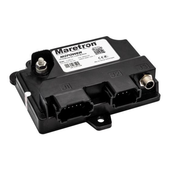
- Page 2 CLMD12 User's Manual Revision History Revision Description Internal Review Second Review Initial Release Updated Accessory Part Numbers Removed requirement for parallel resistors for LED loads Added ability to parallel breakers together for increased current Added Product Image, Update table of contents Page ii Revision 1.6...
-
Page 3: Table Of Contents
Table of Contents 1 Notices ..........................1 2 Introduction ........................... 1 2.1 Firmware Revision ....................2 2.2 CLMD12 Features ....................2 2.3 Accessories ......................2 2.3.1 Connectors ....................2 2.3.2 Bypass Module ....................3 2.4 Quick Install ......................3 2.5 Theory of Operation ....................3 2.5.1 Electronic Circuit Breakers................ - Page 4 8 Mechanical Drawing ......................35 9 Technical Support ....................... 36 10 Installation Template ......................37 11 Maretron (2 Year) Limited Warranty ..................38 Table of Figures Figure 1 – Output Channel Schematic ..................5 Figure 2 – Discrete Input Impedance Model ................8 Figure 3 –...
- Page 5 Table of Appendices Appendix A – NMEA 2000 ® Interfacing..................A1 Revision 1.6 Page v...
-
Page 7: Notices
Carling Technologies. 2 Introduction Congratulations on your purchase of the Maretron MPower CLMD12 12 Channel DC Load Module. Carling has designed and built your CLMD12 to the highest standards for years of dependable and accurate service. -
Page 8: Firmware Revision
CLMD12 User's Manual The Maretron CLMD12 is designed to operate within the harsh demands of the marine environment. However, no piece of marine electronic equipment can function properly unless installed, configured, and maintained in the correct manner. Please read carefully and follow these instructions for installation, configuration, and usage of the Maretron CLMD12 in order to ensure optimal performance. -
Page 9: Bypass Module
MPower 12 Channel DC Bypass CBMD12 Module 2.4 Quick Install Installing the Maretron CLMD12 involves the following steps. Please refer to the individual sections for additional details. 1. Unpack the box (Section 3.1) 2. Choose a mounting location (Section 3.2) 3. -
Page 10: Electronic Circuit Breakers
(please refer to Appendix A for details). The breakers can be monitored and/or controlled through use of the Breaker/Switch component in the Electrical Distribution category of the Maretron display products listed above. In addition, the current through each breaker may be monitored through the Breaker/Switch Current component in the Electrical Distribution category of Maretron display products. -
Page 11: Overcurrent Protection
Voltage Input stud Channel Output 55 K 36 V Current Current Sense Sense DRIVER Figure 1 – Output Channel Schematic 2.5.1.1 Overcurrent protection The overcurrent protection has two purposes: to protect the CLMD12 and to protect the load circuits. The CLMD12 is protected by fast acting overcurrent latches in hardware that allow for overcurrent conditions that will not damage the output control circuit. -
Page 12: Load Protection Current Limit
CLMD12 User's Manual Channel current in Amperes VS time to non-configurable overcurrent shutdown in Seconds for a steady current. 10A channel 5A channel 12A channel Time (sec) 2.6 Load protection current limit The configurable load protection current limit provides three parameters to customize the overcurrent protection of the load. -
Page 13: Paralleling Breakers
2.8 Paralleling Breakers Breakers can be paralleled for higher current capacity: • Only parallel two breakers with the same current rating. • Wiring recommendation: Run two breakers wired together with matched impedance. • Please note that the maximum current rating when two breakers are paralleled is typically 180% of the single channel rating. -
Page 14: Installation
OFF indication. 3 Installation 3.1 Unpacking the Box When unpacking the box containing the Maretron CLMD12, you should find the following items: 1 – CLMD12 – 12 Channel DC Load Module 1 – CLMD12 User’s Manual 1 –... -
Page 15: Nmea 2000
® ® CLMD12 to an NMEA 2000 network using a Maretron NMEA 2000 cable (or compatible cable) by connecting the female end of the cable to the CLMD12 (note the key on the male connector and keyway on the female connector). Be sure the cable is connected securely and that the collar on the cable connector is tightened firmly. -
Page 16: Breaker Connections
CLMD12 User's Manual 3.4.2 Breaker Connections The CLMD12 breaker connections are made by connecting to the 12-pin J1 connector. The pin number on the J1 connector corresponds to a breaker number, which is represented as an indicator number in the 127501 Binary Status Report message or as a Connection ID in the 127500 Load Controller Connection &... -
Page 17: Dc Power Connection
There are several configurable items within the CLMD12, which are detailed in the remainder of this section. ® You configure the CLMD12 using Maretron N2KAnalyzer or Carling G2Analyzer software. The following subsections describe the configurable parameters in the CLMD12. - Page 18 CLMD12 User's Manual Page 12 Revision 1.6...
- Page 19 Revision 1.6 Page 13...
-
Page 20: Label
Figure 5 – CLMD12 General Tab 3.5.1.1 Label This text box allows you to assign a text label to the device. This label is visible in Maretron analysis and display products and allows you to easily identify the particular device. -
Page 21: Input Voltage
3.5.1.5 Serial Number Invalid When lit, this read-only field indicates that the CLMD12 does not contain a valid serial number. Please contact Maretron technical support for assistance. 3.5.1.6 Breaker #n This section contains settings for the specified circuit breaker. One of these sections is present for each of the breakers in the unit. - Page 22 CLMD12 User's Manual 3.5.1.6.6 ECB Model This read-only field shows the revision level of the ECB (electronic circuit breaker). 3.5.1.6.7 Trip Delay This parameter allows you to configure the trip delay for the breaker (the current through the breaker must exceed the current rating of the breaker for this amount of time for the breaker to trip).
- Page 23 3.5.1.6.16 Voltage This read-only field shows the real-time voltage at the load terminal of the breaker. 3.5.1.6.17 Flash Map This parameter allows you to configure a breaker to use a flash map. A value of 0 means that the breaker is not assigned to any flash map, and a value of 1 through 15 assigns the breaker to the flash map corresponding to that number.
-
Page 24: Flash Map
CLMD12 User's Manual 3.5.2 Flash Map The Flash Function allows control of a breaker to be periodic. Common uses of this function include turning off a head fan or light after a set period of time, etc. Three parameters dictate the behavior of the circuit and are detailed below. -
Page 25: On Time
0 will repeat the cycle indefinitely, and values in the range of 1 cycle to 255 cycles will execute that number of cycles. 3.5.2.2 On Time This parameter allows you to configure the time that a breaker will be ON during a cycle. This can be set to a value in the range of 0 seconds to 6553.5 seconds in increments of 0.1 seconds. -
Page 26: Data Instance
CLMD12 User's Manual Figure 7 – CLMD12 Discrete I/O Tab 3.5.3.1 Data Instance This parameter allows you to configure the data instance of the 127501 Binary Status Report message that will be used to control this discrete I/O circuit. To assign a discrete input from this device to this discrete I/O circuit, enter the instance value assign to this device (the value of the “Instance”... -
Page 27: Manufacturer Code
3.5.3.3 Manufacturer Code This parameter allows you to configure the manufacturer code that must be reported by the device transmitting the 127501 Binary Status Report message that will be used to control this discrete I/O circuit. Setting this value to 2047 means that any manufacturer code will be accepted. -
Page 28: Instance
CLMD12 User's Manual Figure 8 – CLMD12 Inputs Tab 3.5.4.1 Instance This read-only field indicates the data instance used for this box. The value that appears here can be changed by setting the “Device Instance” parameter on the Advanced tab. 3.5.4.2 Channel 3.5.4.3 Label Each channel has a text label you can set to identify the input signal monitored by that channel... -
Page 29: Advanced
3.5.4.3.1 OnLevel(s) This parameter allows you to configure the voltage level on the input signals that corresponds to an ON status on the input as reported on the network. You can use any of the following settings: • High – a high voltage level on the input is represented as an ON value on the network. A high impedance or a low voltage level on the input is represented as an OFF value on the network. -
Page 30: Device Instance
CLMD12 User's Manual Figure 9 – CLMD12 Advanced Tab 3.5.5.1 Device Instance This parameter allows you to configure the NMEA 2000 device instance used by the device. This value is also used as the data instance in the 127501 Binary Status Report messages transmitted by the device and can be seen on the General Tab as well as the Inputs Tab labeled as “Instance”. -
Page 31: Receive Pgn 127501 Via 126208
This parameter allows you to configure from which devices the CLMD12 will accept 126208 NMEA Commands of the 127501 Binary Status Report message. There are two settings for this parameter: • From Carling/Maretron devices only • From any manufacturer’s device 3.5.5.7 Box Status 3.5.5.7.1 Box Current... -
Page 32: Installation Description #1, #2
CLMD12 User's Manual Figure 10 – CLMD12 Installation Description Tab 3.5.6.1 Installation Description #1, #2 This device, along with all other certified NMEA devices, has two user-programmable installation description fields. You may program these fields with information specific to the device, such as date installed, the initials/name of the installer, the physical location of the device, etc. -
Page 33: Status Led
Figure 11 – CLMD12 Control Tab 3.5.7.1 Status LED When lit, this read-only field indicates that the breaker is in the ON state. When dim, this field indicates that the breaker is in the OFF state. 3.5.7.2 ON/OFF Buttons The ON button allows you to switch the breaker into the ON state. The OFF button allows you to switch the breaker into the OFF state. -
Page 34: Operation
Three parameters dictate the behavior of the circuit and are set via the Maretron N2KAnalyzer utility. A maximum of 15 flash table entries may be defined. -
Page 35: Manual Bypass
OFF when the input becomes inactive. 4.4 Manual Bypass The Maretron Mechanical Bypass Module (CBMD12) P/N A3675 can be installed in conjunction with the CLMD12. The bypass module provides a manual method (On/Off switch) to control loads by providing power to each load in case of CLMD12 malfunction and/or NMEA 2000 network failure. -
Page 36: Maintenance
CLMD12 load terminal and the load device. Failure to do so can result in serious bodily harm. Regular maintenance is important to ensure continued proper operation of the Maretron CLMD12. Perform the following tasks periodically: Page 30 Revision 1.6... -
Page 37: Troubleshooting
6 Troubleshooting If you notice unexpected operation of the Maretron CLMD12, follow the troubleshooting procedures in this section to remedy simple problems. If these steps do not solve your problem, please contact Maretron Technical Support (refer to Section 8 for contact information). - Page 38 CLMD12 User's Manual • If you are controlling the load via a DSM-Series display, You can see, but not control, the state of a ensure that it is running at least firmware revision 1.4.10. • If you are controlling the load via N2KView software, breaker/switch ensure that you have a switch control license for the software.
-
Page 39: Technical Specifications
As Carling is constantly improving its products, all specifications are subject to change without notice. Maretron products are designed to be accurate and reliable; however, they should be used only as aids to navigation and not as a replacement for traditional navigation aids and techniques. - Page 40 CLMD12 User's Manual Electrical Parameter Value Comment Voltage Input Range 6.5 to 32 VDC DC Voltage ® Power Consumption 150 mA @ 12 VDC NMEA 2000 Interface 70 mA @ 24 VDC ® Load Equivalence Number (LEN) NMEA 2000 Spec. (1LEN = 50 mA) Reverse Battery Protection Indefinitely Load Dump Protection...
-
Page 41: Mechanical Drawing
Parameter Standard Conditions Simulated Solar Radiation EN 60068-2-5:2010 Procedure = B, 10 days @ 40°C Altitude (Transport) EN 60068-2-13:1999 = Sea Level, ALT = 13600m Altitude (Operational) EN 60068-2-13:1999 = Sea Level, ALT = 4850m Humidity (Soak) EN 60068-2-78:2002 RH = 93% +/-3%, Exposure 10 days Humidity - Cyclic EN 60068-2-30:2005 RH (>... -
Page 42: Technical Support
CLMD12 User's Manual 9 Technical Support If you require technical support for Maretron products, you can reach us in any of the following ways: Telephone: 1-866-550-9100 Fax: 1-602-861-1777 E-mail: support@maretron.com World Wide Web: http://www.maretron.com Mail: Carling Technologies, Inc. Attn: Maretron Technical Support 120 Intracoastal Pointe Dr. -
Page 43: Installation Template
10 Installation Template Please check the dimensions before using the following diagram as a template for drilling the mounting holes because the printing process may have distorted the dimensions. Figure 13 – Mounting Surface Template Revision 1.6 Page 37... -
Page 44: Maretron (2 Year) Limited Warranty
Warranty Return Procedure: To apply for warranty claims, contact Carling Technologies or one of its Maretron dealers to describe the problem and determine the appropriate course of action. If a return is necessary, place the product in its original packaging... - Page 45 Appendix A – NMEA 2000 ® Interfacing This appendix is intended to relate specific characteristics of the CLMD12 to how they are ® communicated via NMEA 2000 messages in order to help ascertain whether the messaging ® implemented by the CLMD12 is compatible with other NMEA 2000 products.
- Page 46 CLMD12 User's Manual 3: Indicator #2 – This field indicates the state of the solid-state breaker on output channel 4: Indicator #3 – This field indicates the state of the solid-state breaker on output channel 5: Indicator #4 – This field indicates the state of the solid-state breaker on output channel 6: Indicator #5 –...
Need help?
Do you have a question about the MPOWER CLMD12 and is the answer not in the manual?
Questions and answers