
Related Manuals for Hyundai hirun N100 plus


Summary of Contents for Hyundai hirun N100 plus
- Page 1 DOC. NO HHIS-WZ-PK-008 (02) Accredited by the RvA ISO 9001/ISO 14001/OHSAS 18001(N/A) REGISTERED FIRM DNV Certification B.V., THE NETHERLANDS plus VECTOR INVERTER INSTRUCTION MANUAL...
- Page 2 plus CONTENTS Page 1. Safety Message 2. Receiving and Checking 3. General Specifications 4. External dimensional diagrams and Identifying the parts 5. Mounting 6. Wiring 7. Operation 8. Using Intelligent Input Terminals 9. Function List 10. Protective functions 11. Trouble shooting Tips 12.
- Page 3 plus 1. Safety Messages plus For the best results with the N100 Series inverter, carefully read this manual and all of the warning labels attached to the inverter before installing and operating it, and follow the instructions exactly. Keep this manual handy for quick reference.
- Page 4 To order a copy of this manual, or if your copy has been damaged or lost, contact your representative. Hyundai is not responsible for any modification of the product made by the user, since that will void the guarantee.
- Page 5 plus Index to Dangers and Cautions in This Manual Installation-cautions for Mounting Procedures CAUTION Be sure to install the unit on flame-resistant material such as a steel plate. Otherwise, there is the danger of fire. Be sure not to place any flammable materials near the inverter.
- Page 6 plus CAUTION Be sure to maintain the specified clearance area around the inverter and to provide adequate ventilation. Otherwise, the inverter may overheat and cause eguipment damage or fire. Be sure to install the inverter in a well-ventilated room which does not have direct exposure to sunlight, a tendency for high temperature, high humidity of dew condensation, high levels of dust, corrosive gas, explosive gas, inflammable gas,...
- Page 7 plus Wiring-Dangers for Electrical Practices and Wire Specifications DANGER Be sure to connect grounding terminal. Otherwise, there is a danger of electric shock and/or fire. Wiring work shall be carried out only by qualified personnel. Otherwise, there is a danger of electric shock and/or fire. Implement wiring after checking that the power supply is off.
- Page 8 plus Wiring-Cautions for Electrical Practices CAUTION Be sure that the input voltage matches the inverter specifications: Single-phase 200 to 230 V 50/60Hz Three-phase 200 to 230V 50/60Hz Three-phase 380 to 460V 50/60Hz Otherwise, there is the danger of injury and/or fire . Be sure not to input a single phase to a three-phase only type inverter.
- Page 9 plus CAUTION Fasten the screws with the specified fastening torque. Check for any loosening of screws. Otherwise, there is the danger of fire. Be sure to install a fuse in the wire for each phase of the main power supply to the inverter. Otherwise, there is the danger of fire.
- Page 10 plus Dangers for Operations and Monitoring DANGER Be sure to turn on the input power supply after closing the front case. While being energized, be sure not to open the front case. Otherwise, there is the danger of electric shock and/or fire. Be sure not to operate the switches with wet hands.
- Page 11 plus DANGER After the operation command is given, if the alarm reset is conducted, it will restart suddenly. Be sure to set the alarm reset after verifying the operation command is off. Otherwise, it may cause injury to personnel. Be sure not to touch the inside of the energized inverter or to put any conductive object into it.
- Page 12 plus Cautions for Operations and Monitoring CAUTION The heat sink fins will have a high temperature. Be careful not to touch them. Otherwise, there is the danger of getting burned. Install a holding brake separately if necessary. Otherwise, there is the danger of accident. Check the direction of the motor, any abnormal motor vibrations or noise.
- Page 13 plus Dangers and cautions for Troubleshooting Inspection and Maintenance DANGER Wait at least five(5) minutes after turning off the 12-1 input power supply before performing maintenance or an inspection. Otherwise, there is the danger of electric shock. Make sure that only qualified personnel will 12-1 perform maintenance, inspection, and part replacement.
- Page 14 plus WARNING DISPLAY WARNING Risk of electric shock. DANGER Before opening the cover, wait at least 5 minutes until DC bus capacitors discharge. Ensure proper earth connection. Refer to the user's manual before installation and operation. A warning label is displayed on the terminal cover of the inverter, as shown in the figure.
- Page 15 plus Do not Run/Stop operation by switching on/off electromagnetic contactors (Mc0, Mc1) on the primary or secondary sides of the inverter. Operate the inverter by Run/Stop commanding [FW/RV]. Inverter Motor Terminal Surge Voltage Suppression Filter (for the 400V class) In a system using an inverter with the voltage control PWM system, a voltage surge caused by the cable constants such as the cable length (especially when the distance between the motor and inverter is 10m or more) and cabling method may occur at the motor terminals.
- Page 16 plus In the cases below involving a general-purpose inverter, a large peak current flows on the power supply side, sometimes destroying the converter module. The unbalance factor of the power supply is 3% or higher. The power supply capacity is at least 10 times greater than the inverter capacity(and the power supply capacity, 500kVA or more).
- Page 17 − Output : 0.5-400Hz 200 230V 3ph 7.0A Output Rating: Frequency, voltage, phase current MFG NO : Customer Service Center HYUNDAI Manufacturing codes: 052)230-8445/6 Lot number, date, etc. HEAVY INDUSTRIES CO., LTD. plus If any part of N100...
- Page 18 plus N100 INSTRUCTION MANUAL plus 3. N100 Inverter Standard Specifiations. Model-specific tables for 200V and 400V class inverters plus The following two tables are specific to N100 inverters for the 200V and 400V class model groups. The table on page 3-3 gives the general specifications that apply to both voltage class groups.
- Page 19 plus N100 INSTRUCTION MANUAL 400V Class Specifications Item plus plus plus plus plus N100 N100 N100 N100 N100 plus Model N100 series -004HF -007HF -015HF -022HF -037HF 0.75 Applicable motor size *2 Rated capacity(200V)kVA 3-phase : 380 to 460V 10%, Rated input voltage 50/60Hz 5% Rated output voltage *3...
- Page 20 plus N100 INSTRUCTION MANUAL General Specifications plus The following table applies to all N100 inverters. General Specifications Item Protective housing *1 Enclosed type(IP20) Space vector PWM control Control method Output frequency range *4 0.01 to 400Hz Digital command : 0.01% of the maximum frequency Frequency accuracy Analog command : 0.1% of the maximum frequency Digital : 0.01Hz(100Hz and less), 0.1Hz...
- Page 21 plus N100 INSTRUCTION MANUAL General Specifications Item RUN(run status signal), FA1 (frequency arrival signal), FA2 (setting Frequency arrival signal), Intelligent output OL(overload advance notice signal), OD(PID error terminal deviation signal), AL(alarm signal) Analog meter (DC0 10V full scale, Max. 1mA) Analog output frequency, Analog output current and Frequency monitor Analog output voltage signals selectable.
- Page 22 Footnotes for the preceding tables : 1. The protection method conforms to JEM 1030. 2. The applicable motor refers to HYUNDAI standard 3-phase motor (4-pole). To use other motors, care must be taken to prevent the rated motor current(50/60Hz) from exceeding the rated output current of the inverter.
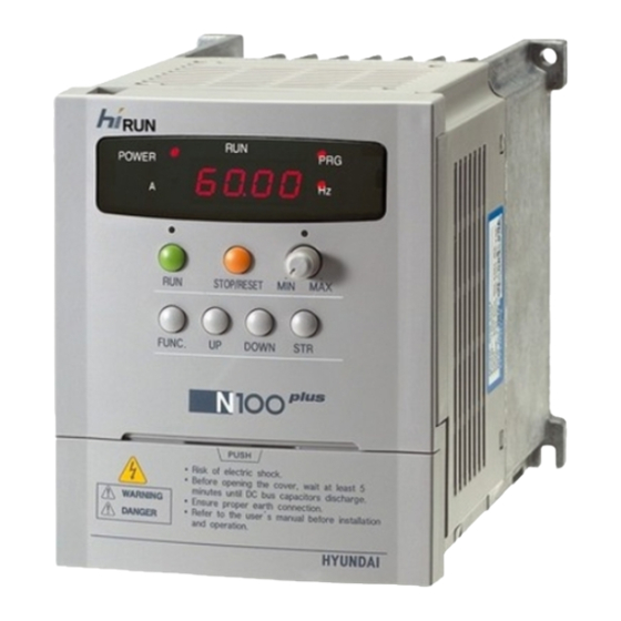
- Page 23 plus N100 INSTRUCTION MANUAL 4. External Dimension Diagrams and Identifying the parts Main Physical Features Display part Front cover Control key Terminal cover(Note) Communication port Main circuit terminal Mounting hole Cooling fan Fan cover Ground Terminal Removing terminal cover : Use a hand and press on the terminal cover surface to remove it.
- Page 24 plus N100 INSTRUCTION MANUAL Front cover Bolt Wiring cover Use a screwdriver to loosen the Bolt on the front cover. Notice the wiring cover that lifts out to allow full access to the terminals for wiring. After removing terminal cover, locate the recessed retention screw on the left side main front panel.
- Page 25 plus N100 INSTRUCTION MANUAL Inverter Dimensions for Mounting plus The N100 Series inverters have a digital operator as a standard and contains all the elements for monitoring and setting parameters. The optional remote operator may be available for remote operation. Locate the applicable drawing on the following pages for your inverter.
- Page 26 plus N100 INSTRUCTION MANUAL 037LF 022HF 037HF Dimension table by the capacity External dimension(mm) Installation dimension(mm) TYPE (W H D) (W H. ) 004SF 115 130 135 1-phase 007SF 105 120,M4 200V class 015SF 115 130 155 External dimension(mm) Installation dimension(mm) TYPE (W H D) (W H.
- Page 27 plus N100 INSTRUCTION MANUAL 5. Installation Choosing a Mounting Location CAUTION Be sure to install the unit on flame-resistant material such as a steel plate. Otherwise, there is the danger of fire. Be sure not to place any flammable materials near the inverter. Otherwise, there is the danger of fire.
- Page 28 plus N100 INSTRUCTION MANUAL To summarize the cautions messages-You will need to find a solid, non- flammable, vertical surface that is a relaticely clean and any envirnment. In order to ensure enough room for air circulation around the inverter to aid in cooling, maintain the specified clearance around the inverter specified in the diagram.
- Page 29 plus N100 INSTRUCTION MANUAL 6.Wiring DANGER Be sure to ground the unit. Otherwise, there is a danger of electric shock and/or fire. Wiring work shall be carried out only by qualified personnel. Otherwise, there is a danger of electric shock and/or fire. Implement wiring after checking that the power supply is off.
- Page 30 plus N100 INSTRUCTION MANUAL 6.1 Wiring the main circuit You will connect main circuit terminal wiring to the input of the inverter. For wiring, open the front cover and wiring cover. plus Ex)N100 -004LF P RB Inverter Thermal Thermal Relay Relay Power supply Motor...
- Page 31 plus N100 INSTRUCTION MANUAL NOTE1) Install mechanically interlocked switches Mc1 and Mc2 in case of exchange by using commercial power supply and inverter. MCCB Inverter Power Motor supply Install an earth leakage breaker(or MCCB) on the power supply side NOTE2) of the inverter.
- Page 32 plus N100 INSTRUCTION MANUAL 6.2 Wiring the control circuit control circuit terminal CM1 6 1 P24 H O OI L FM CM2 12 11 Example of control circuit terminal O OI L FM 12 11 CM1 6 1 P24 Frequency Frequency meter command 27 VDC...
- Page 33 plus N100 INSTRUCTION MANUAL Use a twisted and shielded wire for the signal line, and cut the shielded Note2) covering as shown in the diagram below. Make sure that the length of the signal line is 20 meters or less Insulate No grounding necessary ²...
- Page 34 plus N100 INSTRUCTION MANUAL 6.3 Connecting to PLCs Note 1) In order to use terminal CM1, install the reverse prevention Diode D N100 Inverter MCCB motor braking resistor Alarm output contact diode DC24V...
- Page 35 plus N100 INSTRUCTION MANUAL 6.4 Application wiring apparatus & options Determination of wire and Fuse size Applicable equipment Motor Wiring Application Output Magnetic contactor Power Signal Leakage braker Inverter Model (kw) (MC) Lines Lines (MCCB) plus (Note5) N100 -004SF (Note6) plus HBS-33(5AT) HMC 10W...
- Page 36 plus N100 INSTRUCTION MANUAL Standard Apparatus(3-phase input reference) Power supply Wiring Applicable equipment Motor Inverter model plus output(kw) (N100 Series) Power lines Signal lines Fuse(class J) rated 600V plus N100 -004SF Fuse plus N100 -004LF 1.25 0.14 plus N100 -007SF Electroma- 0.75 plus...
- Page 37 N100 INSTRUCTION MANUAL Note 1) The applicable equipment is for HYUNDAI standard four pole squirrel cage motor. Note 2) Be sure to consider the capacity of the circuit breaker to be used. Note 3 ) Be sure to use larger wire for power lines if the distance exceeds 20m.
- Page 38 plus N100 INSTRUCTION MANUAL 6.5 Terminal array & Terminal function (1) Terminal array <Main circuit> Width(mm) Main circuit terminal Model Screw plus N100 RB U V W 004SF 015SF 004LF CASE 037LF 004HF 037HF <Control circuit> Model Screw Width(mm) Control circuit terminal diameter plus N100...
- Page 39 plus N100 INSTRUCTION MANUAL (2) Terminal Function Main circuit Terminal Terminal Terminal Function name symbol Connect the input Main power R, S, T power supply 220V, supply input 440V Inverter U, V, W Connect the MOTOR output S T P RB U V W External Connect the braking RB, P...
- Page 40 plus N100 INSTRUCTION MANUAL Control circuit Terminal Terminal Signal Terminal name Terminal function symbol Power supply for frequency setting 0 5VDC Frequ- 0 5VDC(standard), ency Voltage frequency command signal 0 10VDC, input comm- impedance 10 signal Current frequency command signal 4 20mA, input impedance Common terminal for frequency command Intelligent output terminal:...
- Page 41 plus N100 INSTRUCTION MANUAL 7. Operation DANGER Be sure to turn on the input power supply after closing the front case. While being energized, be sure not to open the front case. Otherwise, there is the danger of electric shock Be sure not to operate the switches with wet hands.
- Page 42 plus N100 INSTRUCTION MANUAL CAUTION The heat sink fins will have a high temperature. Be careful not to touch them. Otherwise is the danger of getting burned. The operation of the inverter can be easily changed from low speed to high speed.
- Page 43 plus N100 INSTRUCTION MANUAL 7.2 Powerup test The following instructions apply to the power up test. The operation from the standard operator Frequency setting, Run and stop command are controlled as follows : Frequency setting select the potentiometer STOP/RUN : select the RUN and STOP key MCCB Power...
- Page 44 plus N100 INSTRUCTION MANUAL Check the following before and during the powerup test. CAUTION Is the direction of the motor correct? Otherwise, there is the danger of equipment damage. Were there any abnormal motor vibrations or noise? Otherwise, there is the danger of equipment damage. NOTE1) 1.
- Page 45 plus N100 INSTRUCTION MANUAL 8. Using intelligent terminals 8.1 Intelligent terminal lists Terminal Description Terminal name symbol SWF Switch Output freguency Forward ON (closed):Forward run Forward OFF(open): stop RUN/STOP terminal Reverse SWR Switch ON (closed):Reverse ON OFF OFF(open): stop Reverse RUN/STOP When SWF and SWR commands are active at the same terminal...
- Page 46 plus N100 INSTRUCTION MANUAL Terminal Description Terminal name symbol Signal source Common terminal for intelligent input terminals. for input External power External power connection terminal for intelligent input supply terminal terminals. for input The External frequency voltage commanding is 0 to 5VDC Frequency command as a standard.
- Page 47 plus N100 INSTRUCTION MANUAL Terminal Description Terminal name symbol Frequency arrival [FA1][FA2] signals is indicated Output terminal when the output frequency accelerates and specification decelerates to arrive at a constant frequency. open-collector Frequency output 27V DC max F01 set value 50 max Time C M2 12...
- Page 48 plus N100 INSTRUCTION MANUAL 8.2 Monitor terminal function Terminal Name : Monitor terminal [FM] (analog) The inverter provides an analog output terminal primary for frequency monitoring on terminal [FW] (output frequency, Output current, and output voltage monitor signal). Parameter C17 selects the output signal data. When using the analog motor for monitoring, use scale reactor C18 and C19 to adjust the [FM] output so that the maximum frequency in the inverter corresp-...
- Page 49 plus N100 INSTRUCTION MANUAL 8.3 Intelligent Input Terminal Function Forward Run/Stop[FW] and Reverse Run/Stop Command[RV] When you input the Run command via the terminal [FW], the inverter executes the Forward Run command (high) or Stop command(low). When you input the Run command via the terminal [RV], the inverter executes the Reverse Run command(high) or Stop command(low).
- Page 50 plus N100 INSTRUCTION MANUAL Multi-Speed Select [CF1][CF2][CF3][CF4] The inverter provides storage parameters for up to 16 different target frequencies (speeds) that the motor output uses for steady-state run condition. These speeds are accessible through programming four of the intelligent terminals as binary-encoded inputs CF1 to CF4 per the table . These can be any of the six inputs, and in any order.
- Page 51 plus N100 INSTRUCTION MANUAL speed0 speed1speed2 speed3 speed4 speed5 speed6 speed7 speed8 speed9 speed10 speed11 speed12 speed13 speed14 speed15 Control circuit terminal Multi-speed Set code Set value Speed 0 Speed 1 Speed 2 10Hz Speed 3 15Hz Speed 4 20Hz Speed 5 30Hz Speed 6...
- Page 52 plus N100 INSTRUCTION MANUAL Standard operator option code Set the parameter [ ] to [ C 01 C 06 Terminal Option Description Function Name State Symbol Code Valid for inputs: C01,C02,C03,C04,C05,C06 Example: Required setting F01, A11 to A25 CF4 CF3 CF2 CF1 FW Notes: When programming the multi-speed SW6 SW5 SW4 SW3 SW2 SW1...
- Page 53 plus N100 INSTRUCTION MANUAL Jogging Command [JG] [JG] terminal When the terminal [JG] is turned on and the Run command is issued, the inverter [FW,RV] outputs the programmed jog frequency (Run) to the motor. Use a switch between Motor terminals [CM1] and [P24] to activate time speed Jog decel type...
- Page 54 plus N100 INSTRUCTION MANUAL Second Control Function [SET] If you assign the [SET] function to a logic terminal, the inverter will display the Sxx numbered parameters, allowing you to edit the second motor parameters. These parameters store an alternate set of motor characteristic parameters.
- Page 55 plus N100 INSTRUCTION MANUAL Two-stage Acceleration and Deceleration[2CH] When terminal [2CH] is turned on, the inverter changes the rate of acceleration [FW, RV] and deceleration from the initial settings F 02 acceleration time1) and [2CH] F 03 (deceleration time1) to use the second set of acceleration / deceleration values.
- Page 56 plus N100 INSTRUCTION MANUAL Free-run stop [FRS] When the terminal [FRS] is turned on, the inverter stops the output and the motor enters the free-run state (coasting). If terminal [FRS] is turned off, the output resumes sending power to the motor if the Run command is still active. The free-run stop feature works with other parameters to provide flexibility in stopping and starting motor rotation.
- Page 57 plus N100 INSTRUCTION MANUAL External Trip [EXT] When the terminal [EXT] is turned on, the inverter enters the trip state, indicates error code , and stop the output. This is a general purpose interrupt type E 12 feature, and the meaning of the error depends on what you connect to the [EXT] terminal.
- Page 58 plus N100 INSTRUCTION MANUAL Unattended Start Protection [USP] If the Run command is already set when power is turned on, the inverter starts running immediately after power up. The Unattended Start Protection (USP) function prevents that automatic start up, so that the inverter will not run with- out outside intervention.
- Page 59 plus N100 INSTRUCTION MANUAL Terminal Input Option Description Function Name Symbol Code State On power up, the inverter will not resume a Run command (mostly used in the Us) Unattended Sart Protection On power up, the inverter will not resume a Run command that was active before power loss C01,C02,C03,C04,C05,C06 Valid for inputs:...
- Page 60 plus N100 INSTRUCTION MANUAL Analog Input Current/Voltage Select [AT] The [AT] terminal selects whether the inverter uses the voltage [O] or current [OI] input terminals for external frequency control. When the switch between the terminals [AT] and [CM1] is on, it is possible to set the output frequency by applying a current input signal at [OI]-[L].
- Page 61 plus N100 INSTRUCTION MANUAL Reset Inverter [RS] The [RS] terminal causes the inverter to execute the reset operation. If the inverter is in Trip Mode, the reset cancels the Trip [RS]terminal state. When the switch between the set approx.30 terminals [RS] and [CM1] is turned on and Alarm output off, the inverter executes the reset operation.
- Page 62 plus N100 INSTRUCTION MANUAL Software Lock[SFT] When the terminal [SFT] is turned on, the data of all the parameters and functions except the output frequency is locked (prohibited from editing). When the data is locked, the keypad keys cannot edit inverter parameters. To edit parameters again, turn off the [SFT] terminal input.
- Page 63 plus N100 INSTRUCTION MANUAL 8.4 Using intellingent output terminals (Initial setting is a-contact [NO]) Frequency Arrival Signal [FA1]/[FA2] Frequency Arrival [FA1] and [FA2] signals indicate when the output frequency accelerates or decelerates to arrive at a constant frequency. Refer to the figure below.
- Page 64 plus N100 INSTRUCTION MANUAL Terminal Option Input Description Function Name Symbol State Code when output to motor is at the set frequency Frequency arrival when output to motor is off, type 1 signal or in any acceleration or deceleration ramp when output to motor is at or above the set frequency the holds for, even if in acceleration...
- Page 65 plus N100 INSTRUCTION MANUAL Run Signal [RUN] When the [RUN] signal is selected as an intelligent output terminal, the inverter outputs a signal on that terminal when it is in the Run Mode. The output logic is active low, and is the open collector type (switch to ground) command FW[RV] Motor...
- Page 66 plus N100 INSTRUCTION MANUAL Overload Advance Notice Signal [OL] When the output current exceeds a preset value, the [OL] terminal signal Current turns on. The parameter C20 sets the Power running C 20 overload threshold. The overload Regeneration set value detection circuit operates during powered motor operation and during regenerative braking.
- Page 67 plus N100 INSTRUCTION MANUAL Output Deviation for PID Control [OD] The PID loop error is defined as the Process variable magnitude(absolute value) of the Current Setpoint difference between the Set point C 23 set value (target value) and the process Variable (actual value).
- Page 68 plus N100 INSTRUCTION MANUAL Alarm Signal output [AL] The Inverter alarm signal is active when a fault has occurred and it is in the Trip Mode. When the fault is cleared the alarm signal becomes inactive. We must make a distinction between the alarm signal [AL] and the alarm relay contacts AL0, AL1and AL2.
- Page 69 plus N100 INSTRUCTION MANUAL 8.5 Alarm Terminal Function Alarm Terminal [AL1, AL2- AL0) The alarm output terminals are connected as shown below by default, or after initialization. The contact logic can be inverted by using the parameter setting C16. The relay contacts normally contact a. Convention uses "normal' to mean the inverter has power and is in Run or Stop Mode.
- Page 70 plus N100 INSTRUCTION MANUAL 8.6 Configuring the Inverter of Multiple Motors Simultaneous Connections For some applications, you may need to connect two motors (wired in parallel) to a single inverter's output. For example, this is common in conveyors applications where two separate conveyors need to have approxi- mately the same speed.
- Page 71 plus N100 INSTRUCTION MANUAL 8.7 Sensorless Vector Control Function description plus plus The N100 inverter has a built-in auto-tuning algorithm. The N100 inverter can be possible to do high-starting torque and high-precision operation. Also, the settings have a second set of parameters for a second motor. The required torque characteristic or speed control characteristic may not be maintained in case that the inverter capacity is move than twice the capacity of the motor in use .
- Page 72 plus N100 INSTRUCTION MANUAL 8.8 Auto-tuning Function description The auto-tuning procedure automatically sets the motor parameter related to sensorless vector control. Since sensorless vector control needs motor parameter, the standard motor parameters have been set at the factory. Therefore, when an inverter exclusive-use motor is used or when a motor of any other manufacture is drive, the motor parameter is detected by auto-tuning because the parameters are not matched.
- Page 73 Note) The motor parameter of N100 is standard data of HYUNDAI standard 4-poles motor. At the sensorless vector control when using different poles motor, operates by using auto-tuning data as a motor parameter.
- Page 74 plus N100 INSTRUCTION MANUAL Setting Method (1) Digital panel Name Setting range Description 0 : auto-tuning OFF auto-tuning 1 : auto-tuning ON mode selection motor data 0 : standard data setting 1 : auto-tuning data 0 4 : 004LF 037LF motor capacity 5 9 : 004HF 037HF motor poles...
- Page 75 plus N100 INSTRUCTION MANUAL Remark 1. If satisfactory performance through auto-tuning cannot be fully obtained, please adjust the motor constants for the observed symptoms according to the table below. Operation Symptom Adjustment Parameter status When low frequency Slowly increase the motor constant H06/H11/ (a few Hz) torque is R1 in relation to auto-tuning data...
- Page 76 plus N100 INSTRUCTION MANUAL 9. Operating the inverter 9.1 Identifying the parts STOP/RESET key RUN LED on when the inverter This key is use for stopping the motor or resetting outputs the PWM errors. (When either operator or terminal is selected, voltage and operating this key works.
- Page 77 plus N100 N100 INSTRUCTION MANUAL 9.3 Key Description [FUNCTION key] This key allows the selection of commands 5 8 . 1 and memorises parameters. When the key is pressed once in the state of, the extension function code selection state is set. 5 8 .
- Page 78 plus N100 INSTRUCTION MANUAL 9.4 Expanded function mode navigational map Using the key to enter the expanded function mode, select expanded H - - A - - b - - C - - S - - function command NO. in mode.
- Page 79 plus N100 INSTRUCTION MANUAL Function List Parameter Monitoring Functions Func- Description Name code Output frequency Real-time display of output frequency to motor, from 0.00 to 400.0 Hz, "Hz" LED ON monitor Real-time display of output current to motor, Output current monitor from 0.0 to 99.9A, "A"...
- Page 80 plus N100 INSTRUCTION MANUAL Func- Description Name code Displays the power consumption at inverter Power consumption starting (W) monitor Operating time accumulation Inverter operating accumulation time(0 9999) monitor(hour) Real operating time Inverter real operating time (0 59) monitor (minute) DC link voltage Displays the inverter DC link voltage(V) Displays the current trip event Trip event monitor...
- Page 81 plus N100 INSTRUCTION MANUAL Basic Function Mode Run- Func- Description Name Defaults time code Edit Standard default target frequency that determines constant motor that deter- mines constant motor speed. setting range is 0.00 to 400.0Hz (1) frequency setting from UP/DOWN key of digital operator.
- Page 82 plus N100 INSTRUCTION MANUAL Expanded Function Mode of A Group Run- Func- Description Name Defaults time code Edit Basic parameter settings Frequency Four options: select codes: commanding 0..Keypad potentiometer (Multi-speed 1..Control terminal input commanding 2..Standard operator method) 3..
- Page 83 plus N100 INSTRUCTION MANUAL Run- Func- Description Name Defaults time code Edit External The starting point(offset) for the active analog input range(0 10V, 4mA 20mA) frequency 0.0% setting range is 0 to 100% in units of 0.1% start rate setting The ending point(offset) for the active External frequency...
- Page 84 plus N100 INSTRUCTION MANUAL Run- Func- Description Name Defaults time code Edit V/F Characteristics Two options: 0..Manual torque boost Torque boost 1..Automatic torque boost mode selection Can boost starting torque between 0 and 100% above normal V/F curve, from 0 to 1/2 base frequency Be aware that excessive torgue boost can cause motor damage and inverter trip.
- Page 85 plus N100 INSTRUCTION MANUAL Run- Func- Description Name time Defaults code Edit DC Braking Settings Sets two options for DC braking DC braking 0..Disable function selection 1..Enable DC braking The frequency at which DC braking frequency 0.50Hz occurs, range is 0.0 to 10.0 Hz in units setting of 0.01Hz The delay from the end of Run command...
- Page 86 plus N100 INSTRUCTION MANUAL Run- Func- Description Name time Defaults code Edit Defines the distance from the center Jump(hysteresis) frequency at which the jump around frequency width occurs. Range is 0.00 to 10.00Hz in setting units of 0.01Hz 0.00Hz PID Control(Note1) Enables PID function, two option codes: PID Function 0..
- Page 87 plus N100 INSTRUCTION MANUAL Run- Run- Func- Func- Description Description Name Name time time Defaults Defaults code code Edit Edit Second Acceleration and Deceleration Functions Duration of 2nd segment of acceleration, range is 0.1 to 3000 sec. Second accelera- Second acceleration can be set by the 10.0sec tion time setting [2CH] terminal input or frequeny...
- Page 88 plus N100 INSTRUCTION MANUAL Run- Func- Func- Description Description Name Name time Defaults Defaults code code Edit Input voltage Set the voltage offset for external analog offset setting signal input input signal adjustment Input voltage Set the voltage gain for external analog 100.0 Gain setting signal input signal adjustment...
- Page 89 plus N100 INSTRUCTION MANUAL Note 1) PID feedback control The PID(Proportional, Integral, Differential) control functions can apply to controlling of fan, the air (water) amount of pump, etc., as well as controlling of pressure within a fixed value. [Input method of target value signal and feedback signal] Set the reference signal according to the frequency setting method or the internal level.
- Page 90 plus N100 INSTRUCTION MANUAL Expanded Function mode of B Group Run- Func- Func- Description Description Name Name Defaults time code code Edit Restart Mode Select inverter restart method, four option codes: 0..Alarm output after trip, no automatic restart 1..Restart at 0Hz 2..
- Page 91 plus N100 INSTRUCTION MANUAL Run- Func- Func- Description Description Name Name Defaults Defaults time code code Edit Electronic Thermal Overload Alarm Setting Set a level between 20% and 120% for Electronic the rated inverter current. 100.0% thermal setting range- 0.2 (inverter rated level setting current) 1.2...
- Page 92 plus N100 INSTRUCTION MANUAL Run- Func- Func- Description Description Name Name Defaults Defaults time code code Edit Software Lock Mode Prevents parameter changes, in four options, option codes: 0..All parameters except b09 are locked when SFT from terminal is on Software lock 1..
- Page 93 plus N100 INSTRUCTION MANUAL Expanded Function Mode of C Group Run- Func- Func- Description Description Name Name Defaults Defaults time code code Edit Input TerminalFunction Select function for terminal 1 <code> 0: Forward run command(FW) 1: Reverse run command(RV) 2: 1 multi-speed command(CF1) : 2 multi-speed command(CF2) Intellingent Input 4: 3 multi-speed command(CF3)
- Page 94 plus N100 INSTRUCTION MANUAL Run- Func- Func- Description Description Name Name Defaults Defaults time code code Edit Input Terminal 4 Select logic convention, two option codes: a/b contact setting 0..normally open [NO] (NO/NC) 1..normally closed [NC] Input Terminal 5 Select logic convention, two option codes: a/b contact setting 0..
- Page 95 plus N100 INSTRUCTION MANUAL Run- Func- Func- Description Description Name Name Defaults Defaults time code code Edit Output Terminal state setting Analog meter Range is 0(45%) to 250(220%), 100.0% gain adjustment resolution is 1 Analog meter Range is -3.0 to 10.0% 0.0% offset adjustment resolution is 0.1...
- Page 96 plus N100 INSTRUCTION MANUAL Expanded function mode of S group Run- Func- Func- Description Description Name Name time Defaults code code Edit 2nd control, Range is 0.0 to 400Hz in units of 0.01Hz Multi-speed 0speed: (It is enabled by the frequency demanding in frequency 60.00Hz the standard operator)
- Page 97 plus N100 INSTRUCTION MANUAL Run- Func- Func- Description Description Name Name Defaults Defaults time code code Edit Range is 0.1 to 999.9sec in units of 0.1sec, 2nd control, 1000 3000sec in units of 1 sec. Second acceleration 10.00sec acceleration can be set by the [2CH] terminal time 2 setting input or frequency transition setting Range is 0.1 to 999.9sec in units of 0.1sec,...
- Page 98 plus N100 INSTRUCTION MANUAL Run- Func- Func- Description Description Defaults Name Name time code code Edit Considering on the overload, the electronic 2nd control, Electronic thermal protects against the motor from thermal overheating characteristic setting 0 ---- SUB, 1 ---- CRT 2nd control 0 : standard motor constants motor...
- Page 99 plus N100 INSTRUCTION MANUAL Run- Func- Func- Description Description Name Name Defaults Defaults time code code Edit 2nd motor setting range 0.001 -30.00 constant R1 auto-tuning data 2nd motor constant R2 setting range 0.001 -20.00 auto-tuning data 2nd motor constant L setting range 0.1 -999.9mH auto-tuning data 2nd motor constant...
- Page 100 plus N100 INSTRUCTION MANUAL Expanded Function mode of H Group Run- Func- Func- Description Description Name Name Defaults Defaults time code code Edit Sensorless Vector Control Two States for auto-tuning function, Auto-tuning option codes: 0..Auto-tuning OFF mode selection 1..Auto-tuning ON Two selections, option codes: Motor data 0..
- Page 101 plus N100 INSTRUCTION MANUAL 10. Protective function The various functions are provided for the protection of the inverter itself, but they may also protection function when the inverter breaks down. Error Cause(s) Name Code When the inverter output current exceeds the rated Overcurrent current by more than approximately 200% during protection...
- Page 102 plus N100 INSTRUCTION MANUAL Other display Contents Display It is displayed when initialization of data is processing (It is not displayed when initialization of history is processing.) It is displayed when Copy function is operated by the remote c o p y operator.
- Page 103 plus N100 INSTRUCTION MANUAL 11. Troubleshooting Tips Symptom/condition Probable Cause Countermeasure Is the frequency command Make sure the parameter source A01 parameter setting A01setting correct? correct? Make sure the parameter Is the Run command source A02setting correct? A02 parameter setting correct? Is power being supplied to Check terminals R, S and...
- Page 104 plus N100 INSTRUCTION MANUAL Symptom/condition Probable Cause Countermeasure Are the connections of Make connections according output terminal U, V, and to the phase sequence of the W correct? motor. In general: Is the phase sequence of The direction of the FWD=U-V-W, and the motor forward or reverse motor is reversed...
- Page 105 plus N100 INSTRUCTION MANUAL Symptom/condition Probable Cause Countermeasure Was power turned off after Edit the data and press the a parameter edit but before store key once pressing the store key? Inverter data is No downloads have occurred. Edits to data are permanently Wait six seconds or more correct stored at power down.
- Page 106 plus N100 INSTRUCTION MANUAL 12. Maintenance and Inspection Please read following safety messages before troubleshooting or performing maintenance on the inverter and motor system. DANGER Wait at least five(5) minutes after turning off the input power supply before performing maintenance of an inspection. Otherwise, there is the danger of electric shock.
- Page 107 plus N100 INSTRUCTION MANUAL 12.2 Inspection Items This chapter provides instructions or checklists for these inspection items: Daily inspection Periodic inspection(approximately once a year) Insulation resistance test(approximately once two years) Conduct the insulation resistance test by short circuiting the terminals as shown below.
- Page 108 plus N100 INSTRUCTION MANUAL Monthly and Yearly Inspection Chart Inspection Inspection Cyelc Item Inspected Criteria Check for... Method MonthYear Extreme Ambient temperature Thermometer, Ambient temperatures between -10 to 40 , hygrometer environment non-condensing & humidity Abnormal Stable environment for Major devices Visual and aural vibration electronic controls...
- Page 109 plus N100 INSTRUCTION MANUAL 12.3 General Inverter Electrical Measurements The following table specifies how to measure key system electrical param- eters. The diagrams on the next page show inverter-motor systems the loca- tion of measurement points for these parameters. Reference Circuit location Measuring instrument Parameter...
- Page 110 plus N100 INSTRUCTION MANUAL The figures below show measurement locations for voltage, current, and power measurements listed in the table on the previous page. The voltage to be measured is the fundamental wave effective voltage. The power to be measured is the total effective power.
- Page 111 plus N100 INSTRUCTION MANUAL 13. Option 13.1 Dynamic Braking Resistor Table For the running motor 200V class 400V class Motor capacity(kW) R(resistor R(resistor WATTAGE WATTAGE value) value) 0.2 KW 180 ohm 0.3 KW 50 ohm 1.5 KW 0.3 KW 100 ohm 0.3 KW 50 ohm 2.2 KW...
- Page 112 plus N100 INSTRUCTION MANUAL 13.2 Remote operator (NOP 100) Using remote operator specified cable, remote operator controls the inverter parameter setting and run command. Because NOP100 contains READ/COPY function, it can be possible to transmit and store the data of inverter, which is set in advance. Specification Description Item...
- Page 113 plus N100 INSTRUCTION MANUAL External Diagram Unit : mm REMOTE OPERATOR REMT READ COPY FUNC STOP plus Remote Operator(NOP100 )
- Page 114 plus N100 INSTRUCTION MANUAL 13.3 Input-side and Output-side AC reactor...
- Page 115 plus N100 INSTRUCTION MANUAL Input - side AC reactor This is useful when harmonic suppression measures must be taken, when the main power voltage Unbalance rate exceeds 3% and the main power capacity exceeds 500KVA, or when a sudden power voltage variation occurs, It also helps to improve the power factor ACL L I - 2.5 ACL L I - 2.5...
- Page 116 plus N100 INSTRUCTION MANUAL Dimension of Input-side AC reactor for power pactor correction Installation Dimension(mm) Weight Voltage Model (kg) ACL-LI-1.5 1.85 ACL-LI-2.5 200V ACL-LI-3.5 ACL-LI-5.5 ACL-LI-7.5 Dimension of Output-side AC reactor for power pactor correction Installation Dimension(mm) Weight Voltage Model (kg) ACL-L-0.4 ACL-L-0.75...
- Page 117 plus N100 INSTRUCTION MANUAL 13.4 Noise filter Reduces the conductive noise on the main power wires generated from the main power supply. Connect to the inverter primary side (input side). Connection of the noise filter Install a noise filter as shown in figure below. The noise filter must be installed as close as possible to the inverter and its wiring distance minimized.
- Page 118 plus N100 INSTRUCTION MANUAL 14. RS485 Communication The communication between inverter and external controller is doing by RS485 using modular connector in cling to inverter controller. - Relation code - Function Initial Description Minimum Maximum Unit Value code b 17 Setting the communication number A 01 3: Communication...
- Page 119 plus N100 INSTRUCTION MANUAL RS485 port specification Pin number Description 1 2 3 4 5 6 7 8 Transmit/Receive side Transmit/Receive-side 24V GND Communication sequence The communication sequence is as follows: External Frame 1 controller Inverter Frame 2 wait time Frame start : Frame start is recognized by signal line data transmitted.
- Page 120 plus N100 INSTRUCTION MANUAL Communication frame type and form External controller transmit frame Number Command Parameter Parameter Count CRC Hi CRC Lo Description Data size Specifications Inverter Communication 1 byte Communication number number 1 byte Frame type 0 06 Command 1 byte : Group 2 byte Parameter...
- Page 121 plus N100 INSTRUCTION MANUAL External transmit frame Communication number Order Parameter Data CRC Hi CRC Lo Description Data size Specifications Target Inverter Communication 1 byte Communication number number 1 byte Frame type Command 0 03 1 byte : Group 2 byte Parameter Parameter 2 byte : Index (Note1)
- Page 122 plus N100 INSTRUCTION MANUAL (Note1) Parameter setting Basic parameter 1 byte : Each group is setting. Group Group 1 byte 2 byte 0 01 0 05 0 02 0 06 0 03 0 07 0 04 2 byte : Parameter number setting. Ex) The case of A60 parameter reading or writing 1 byte : 0 03 2 byte : 0 3C...
- Page 123 plus N100 INSTRUCTION MANUAL (Note2) Data value setting Data value is transmitted except decimal point. Ex1) Output frequency Parameter value Conversion hexadecimal Communication data 1 byte : 0 17 60.00Hz 6000 2 byte : 0 70 Ex2) acc/dec time Parameter value Conversion hexadecimal Communication data 1 byte : 0 00...
- Page 124 plus N100 INSTRUCTION MANUAL Frequency command Parameter 1 byte : 0 00 2 byte : 0 04 setting data output frequency *100 Ex) the case of output frequency command is 60.00Hz Data 6000 transmit 1 byte : 0 17 2 byte : 0 70 16bit CRC generation The step of CRC generation is as follows: 1.
- Page 125 plus N100 INSTRUCTION MANUAL The sequence of addition Byte(01 01) 16-BIT REGISTER Flag 1111 1111 1111 1111 (Exclusive OR) 0000 0001 1111 1111 1111 1110 0111 Shift 1 1111 1111 1111 Shift 2 0011 1111 1111 1111 1 Polynomial 1010 0000 0000 0001...
Need help?
Do you have a question about the hirun N100 plus and is the answer not in the manual?
Questions and answers
Err e07 q ata he