
Related Manuals for Hyundai N5000


Summary of Contents for Hyundai N5000
- Page 1 DOC. NO. HHIS-WZ-PE-500 N5000 N5000 N5000 N5000 MULTI- - - - LEVEL INVERTER MULTI LEVEL INVERTER MULTI MULTI LEVEL INVERTER LEVEL INVERTER INSTRUCTION INSTRUCTION MANUAL INSTRUCTION INSTRUCTION MANUAL MANUAL MANUAL...
- Page 2 • In order to stop or inspect the machine, you must first cut the high voltage completely. • Insulation must be ensured between N5000 and the test equipment before applying electric current for the purpose of test. A. Installation of System and Wiring CAUTION •...
- Page 3 N5000 INSTRUCTION MANUAL N5000 INSTRUCTION MANUAL N5000 INSTRUCTION MANUAL N5000 INSTRUCTION MANUAL SAFETY PRECAUTIONS SAFETY PRECAUTIONS SAFETY PRECAUTIONS SAFETY PRECAUTIONS DANGER • The equipment must be connected to the ground. If not connected to the ground, it may cause shock and fire.
-
Page 4: Table Of Contents
N5000 INSTRUCTION MANUAL N5000 INSTRUCTION MANUAL N5000 INSTRUCTION MANUAL N5000 INSTRUCTION MANUAL Table of Contents Table of Contents Table of Contents Table of Contents TABLE OF CONTENTS CHAPTER 1. GENERAL DESCRIPTIONS......................3 ..................................3 1.1 I NSTRUCTION MANUAL ................................3 1.2 W... - Page 5 N5000 INSTRUCTION MANUAL N5000 INSTRUCTION MANUAL N5000 INSTRUCTION MANUAL N5000 INSTRUCTION MANUAL Table of Contents Table of Contents Table of Contents Table of Contents 4.3.9 Group A Screen 1 ................................38 4.3.10 Group A Screen 2................................41 4.3.11 Group A Screen 3................................43 4.3.12 Group A Screen 4................................45...
-
Page 6: Chapter 1. General Descriptions
If you have any questions regarding the warranty, please contact either your supplier or the local HYUNDAI Distributor. Please refer to the back cover for a list of the local HYUNDAI Distributors. -
Page 7: Chapter 2 Installation And Wiring
N5000 INSTRUCTION MANUAL N5000 INSTRUCTION MANUAL N5000 INSTRUCTION MANUAL N5000 INSTRUCTION MANUAL Chapter2. Installation and Wiring Chapter2. Installation and Wiring Chapter2. Installation and Wiring Chapter2. Installation and Wiring Chapter 2 Installation and Wiring 2.1 Precaution Please observe the environmental guidelines below. -
Page 8: Wiring
N5000 INSTRUCTION MANUAL N5000 INSTRUCTION MANUAL N5000 INSTRUCTION MANUAL N5000 INSTRUCTION MANUAL Chapter2. Installation and Wiring Chapter2. Installation and Wiring Chapter2. Installation and Wiring Chapter2. Installation and Wiring Notice • When cleaning the equipment room, please use a vacuum cleaner lest dust will be stirred up. - Page 9 N5000 INSTRUCTION MANUAL N5000 INSTRUCTION MANUAL N5000 INSTRUCTION MANUAL N5000 INSTRUCTION MANUAL Chapter2. Installation and Wiring Chapter2. Installation and Wiring Chapter2. Installation and Wiring Chapter2. Installation and Wiring...
-
Page 10: Power Terminal Wiring
① ① ① ① Main power input terminals (R, S, T) • N5000 uses 3-phase power source. Do not use single-phase power source. • Connect input power cable to the inverter through the bottom of the transformer panel. -
Page 11: Chapter 3. Specification And Operation
N5000 INSTRUCTION MANUAL N5000 INSTRUCTION MANUAL N5000 INSTRUCTION MANUAL N5000 INSTRUCTION MANUAL C C C C hapter3. Specification and Operation hapter3. Specification and Operation hapter3. Specification and Operation hapter3. Specification and Operation Chapter 3. Specification and Operation Voltage N5000 Capacity... -
Page 12: Specification
N5000 INSTRUCTION MANUAL N5000 INSTRUCTION MANUAL N5000 INSTRUCTION MANUAL N5000 INSTRUCTION MANUAL C C C C hapter3. Specification and Operation hapter3. Specification and Operation hapter3. Specification and Operation hapter3. Specification and Operation 3.1 Specification Item Item Specification Specification Item Item... - Page 13 N5000 INSTRUCTION MANUAL N5000 INSTRUCTION MANUAL N5000 INSTRUCTION MANUAL N5000 INSTRUCTION MANUAL C C C C hapter3. Specification and Operation hapter3. Specification and Operation hapter3. Specification and Operation hapter3. Specification and Operation Item Item Item Item Specification Specification Specification Specification Digital Input (DI): 16 CH.
-
Page 14: Inverter Features
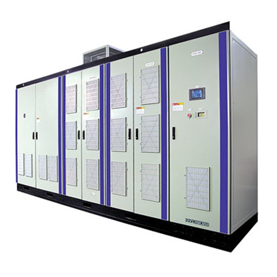
The improved structure enabled N5000 to generate high quality output voltage without a filter that reduces harmonics and to utilize previously established motors and cables. 3.2.1 Composition N5000 is composed of transformer panel, inverter (power cell unit) panel and control panel as shown in Figure 3-1. Figure 3-1 composition of N5000 inverter panel A dry type multi-winding transformer is equipped in transformer panel. - Page 15 N5000 INSTRUCTION MANUAL N5000 INSTRUCTION MANUAL N5000 INSTRUCTION MANUAL N5000 INSTRUCTION MANUAL C C C C hapter3. Specification and Operation hapter3. Specification and Operation hapter3. Specification and Operation hapter3. Specification and Operation power cells so that the total number of power cells is 9.
-
Page 16: Operation
Figure 3-3-A Front view Figure 3-3-B Side view 3.3 Operation N5000 inverter is a Cascaded H-bridge type voltage inverter, which generates 3-phase voltage using serially connected single inverters (power cell unit). 3.3.1 Inverter circuit Figure 3-4 shows the 6kV-class inverter power circuit. 3 phase power supply is supplied to each of the power cell units through input transformer. - Page 17 N5000 INSTRUCTION MANUAL N5000 INSTRUCTION MANUAL N5000 INSTRUCTION MANUAL N5000 INSTRUCTION MANUAL C C C C hapter3. Specification and Operation hapter3. Specification and Operation hapter3. Specification and Operation hapter3. Specification and Operation Figure 3-4-A. 6kV-class N5000 inverter electric circuit...
- Page 18 DC power supplies for the power cells of 18 H-bridge type should be separated to generate 6600V/6000V voltage output in 6kV-class N5000 series inverter. So the number of the 2nd windings is made equal as the number of the power cells by utilizing multi-winding transformer. 6...
-
Page 19: Power Cell Circuit
Figure 3-6 Inverter input current (6kV-class) 3.3.2 Power cell circuit All power cells within N5000 inverter are of the same structure and composed of the same electric circuits. They are operated as a inverter of 3-phase 640V intput type. Each power cell consists of parts of the power supply and the control. -
Page 20: Inverter Output
AC voltage and implements PWM for output voltage using on/off controllable IGBT. 3.3.3 Inverter Output Maximum size of output voltage of each power cell unit is 635V. In the 6kV-class N5000 inverter, six 635V units are serially connected to achieve 3810V and the 3810V units generate 6600 line voltage using Y-connection as shown in figure 3-9. -
Page 21: Control Function
Figure 3-11 voltage output curve of 6kV-class N5000 inverter 3.3.4 Control Function Control part of N5000 inverter is composed of main control part, which is in charge of system operations, controls, failure detections and protections, and the power cell controller that is... - Page 22 N5000 INSTRUCTION MANUAL N5000 INSTRUCTION MANUAL N5000 INSTRUCTION MANUAL N5000 INSTRUCTION MANUAL C C C C hapter3. Specification and Operation hapter3. Specification and Operation hapter3. Specification and Operation hapter3. Specification and Operation composed of CPU board, digital/analog I/O boards and optical converter board. Operator using touch-keypad is installed at the front panel and has SMPS (Switched-mode power supply) for DC5V, ±15V, 24V output to operate main control part and operator etc.
- Page 23 N5000 INSTRUCTION MANUAL N5000 INSTRUCTION MANUAL N5000 INSTRUCTION MANUAL N5000 INSTRUCTION MANUAL C C C C hapter3. Specification and Operation hapter3. Specification and Operation hapter3. Specification and Operation hapter3. Specification and Operation insulated digital output (contact) channels is installed in DIO board. A 4 channel analog input...
-
Page 24: Power Cell Bypass (Optional)
Bypass” method, inverter eliminates only the layer in which power cell failure occurred and keeps running for high inverter efficiency. In N5000 series, additional bypassing switches are installed to run the inverter with lowered voltage for important loads that should not be stopped. So that operator can fix the inverter without stopping. - Page 25 N5000 INSTRUCTION MANUAL N5000 INSTRUCTION MANUAL N5000 INSTRUCTION MANUAL N5000 INSTRUCTION MANUAL C C C C hapter3. Specification and Operation hapter3. Specification and Operation hapter3. Specification and Operation hapter3. Specification and Operation A1 POWER CELL B1 POW ER CELL Bypass Circuit...
- Page 26 N5000 INSTRUCTION MANUAL N5000 INSTRUCTION MANUAL N5000 INSTRUCTION MANUAL N5000 INSTRUCTION MANUAL C C C C hapter3. Specification and Operation hapter3. Specification and Operation hapter3. Specification and Operation hapter3. Specification and Operation Cell Bypass Operation when Power Cell Fails Figure 3-17 shows that the cell bypass function can generate 50% out of rated voltage, 190V, by connecting power cells in layer 2 using SCR in the case of power cell failure of layer 2.
-
Page 27: Chapter 4. Inverter Operation
MCB2 MCCB3 4.2 Inverter operational mode N5000 inverter is a Cascaded H-bridge voltage type inverter that generates 3-phase voltage output by connecting single-phase inverters (Cell unit) serially. 4.2.1 Self-operation by operator Set self-operation mode in the front operator. RUN and STOP operations can be implemented without superior command in this case. -
Page 28: Touch Panel Operator
After stopping, signal that opens K2 VCB of output VCB board is delievered. 4.3 Touch panel operator N5000 inverter sets operational mode by using touch screen operator in front inverter panel. (touch operator: operator). It performs operation monitoring, inverter constant value change, and inverter control constant value change. - Page 29 N5000 INSTRUCTION MAN N5000 INSTRUCTION MAN N5000 INSTRUCTION MAN N5000 INSTRUCTION MANUAL Chapter4 4 4 4 ..Inverter Operation Chapter Inverter Operation Chapter Chapter Inverter Operation Inverter Operation Figure 2. Rear dimension Figure 3. side dimension Figure 4. Bottom dimension 2) Interface between Operator and master controller Communicational interface between operator and master controller is RS-485 serial communication.
- Page 30 N5000 INSTRUCTION MAN N5000 INSTRUCTION MAN N5000 INSTRUCTION MAN N5000 INSTRUCTION MANUAL Chapter4 4 4 4 ..Inverter Operation Chapter Inverter Operation Chapter Chapter Inverter Operation Inverter Operation Num. Num. Num. Num. Item Item Item Item Description...
- Page 31 N5000 INSTRUCTION MAN N5000 INSTRUCTION MAN N5000 INSTRUCTION MAN N5000 INSTRUCTION MANUAL Chapter4 4 4 4 ..Inverter Operation Chapter Inverter Operation Chapter Chapter Inverter Operation Inverter Operation Num. Num. Num. Num. Name Name Name Name Content...
-
Page 32: Operator Screen Organization
N5000 INSTRUCTION MAN N5000 INSTRUCTION MAN N5000 INSTRUCTION MAN N5000 INSTRUCTION MANUAL Chapter4 4 4 4 ..Inverter Operation Chapter Inverter Operation Chapter Chapter Inverter Operation Inverter Operation 4) Operator power specification Item Item Item Item Description... -
Page 33: Operator Common Screen
N5000 INSTRUCTION MAN N5000 INSTRUCTION MAN N5000 INSTRUCTION MAN N5000 INSTRUCTION MANUAL Chapter4 4 4 4 ..Inverter Operation Chapter Inverter Operation Chapter Chapter Inverter Operation Inverter Operation 4.3.3 Operator common screen Display Description Communication between main controller and operator is in normal condition. - Page 34 N5000 INSTRUCTION MAN N5000 INSTRUCTION MAN N5000 INSTRUCTION MAN N5000 INSTRUCTION MANUAL Chapter4 4 4 4 ..Inverter Operation Chapter Inverter Operation Chapter Chapter Inverter Operation Inverter Operation values, name of set value and possible input value range will be changed. If input value is out of range, it will not be accepted.)
-
Page 35: Operation Monitoring Screen Panel
Inverter Operation 4.3.4 Operation monitoring screen panel If master controller of N5000 inverter is powered on, first screen of operator on the front inverter panel displays a picture of figure 9, operation monitoring screen panel, after 3 sec. Overall conditions of the inverter can be monitored thorough this screen. User cannot change the values. - Page 36 N5000 INSTRUCTION MAN N5000 INSTRUCTION MAN N5000 INSTRUCTION MAN N5000 INSTRUCTION MANUAL Chapter4 4 4 4 ..Inverter Operation Chapter Inverter Operation Chapter Chapter Inverter Operation Inverter Operation Accumulated supplying time: displays the accumulated time of powered-on and operation even (11) the inverter has not started.
-
Page 37: Operation Controlling Screen Panel
N5000 INSTRUCTION MAN N5000 INSTRUCTION MAN N5000 INSTRUCTION MAN N5000 INSTRUCTION MANUAL Chapter4 4 4 4 ..Inverter Operation Chapter Inverter Operation Chapter Chapter Inverter Operation Inverter Operation 4.3.5 Operation controlling screen panel Operation controlling screen panel comes out as shown in figure 10 when DOWN( )button or ) button in the CELL monitoring screen panel are touched. - Page 38 N5000 INSTRUCTION MAN N5000 INSTRUCTION MAN N5000 INSTRUCTION MAN N5000 INSTRUCTION MANUAL Chapter4 4 4 4 ..Inverter Operation Chapter Inverter Operation Chapter Chapter Inverter Operation Inverter Operation [Reference 1] Relationship between acceleration, deceleration time and output frequency Set values of acceleration and deceleration time are the time durations to reach base frequency from 0Hz and 0Hz from the base frequency.
-
Page 39: Cell Monitoring Screen Panel
N5000 INSTRUCTION MAN N5000 INSTRUCTION MAN N5000 INSTRUCTION MAN N5000 INSTRUCTION MANUAL Chapter4 4 4 4 ..Inverter Operation Chapter Inverter Operation Chapter Chapter Inverter Operation Inverter Operation 4.3.6 CELL monitoring screen panel CELL monitoring screen panel comes out when DOWN (... -
Page 40: Ctpt Monitoring Screen Panel
N5000 INSTRUCTION MAN N5000 INSTRUCTION MAN N5000 INSTRUCTION MAN N5000 INSTRUCTION MANUAL Chapter4 4 4 4 ..Inverter Operation Chapter Inverter Operation Chapter Chapter Inverter Operation Inverter Operation 4.3.7 CTPT monitoring screen panel CTPT monitoring screen panel comes out when DOWN (... -
Page 41: Function Selecting Menu
N5000 INSTRUCTION MAN N5000 INSTRUCTION MAN N5000 INSTRUCTION MAN N5000 INSTRUCTION MANUAL Chapter4 4 4 4 ..Inverter Operation Chapter Inverter Operation Chapter Chapter Inverter Operation Inverter Operation 4.3.8 Function Selecting Menu Function selecting menu comes out when DOWN (... - Page 42 N5000 INSTRUCTION MAN N5000 INSTRUCTION MAN N5000 INSTRUCTION MAN N5000 INSTRUCTION MANUAL Chapter4 4 4 4 ..Inverter Operation Chapter Inverter Operation Chapter Chapter Inverter Operation Inverter Operation When touching any button in the screen panel, 10KEY screen comes out for inputting values.
- Page 43 N5000 INSTRUCTION MAN N5000 INSTRUCTION MAN N5000 INSTRUCTION MAN N5000 INSTRUCTION MANUAL Chapter4 4 4 4 ..Inverter Operation Chapter Inverter Operation Chapter Chapter Inverter Operation Inverter Operation Figure 15 Acceleration pattern curve (5) Deceleration pattern: set pattern for deceleration in accordance with the loaded value.
- Page 44 N5000 INSTRUCTION MAN N5000 INSTRUCTION MAN N5000 INSTRUCTION MAN N5000 INSTRUCTION MANUAL Chapter4 4 4 4 ..Inverter Operation Chapter Inverter Operation Chapter Chapter Inverter Operation Inverter Operation 4.3.10 Group A Screen 2 ‘Group A Screen 2’ screen panel comes out when DOWN ( ) button in ‘Group A Screen 1’...
- Page 45 N5000 INSTRUCTION MAN N5000 INSTRUCTION MAN N5000 INSTRUCTION MAN N5000 INSTRUCTION MANUAL Chapter4 4 4 4 ..Inverter Operation Chapter Inverter Operation Chapter Chapter Inverter Operation Inverter Operation [EXAMPLE 1] When starting method selection ((6)) is ‘0’.
-
Page 46: Group A Screen 5
N5000 INSTRUCTION MAN N5000 INSTRUCTION MAN N5000 INSTRUCTION MAN N5000 INSTRUCTION MANUAL Chapter4 4 4 4 ..Inverter Operation Chapter Inverter Operation Chapter Chapter Inverter Operation Inverter Operation 4.3.11 Group A Screen 3 ‘Group A Screen 3’ screen panel comes out when DOWN ( ) button in ‘Group A Screen 2’... - Page 47 N5000 INSTRUCTION MAN N5000 INSTRUCTION MAN N5000 INSTRUCTION MAN N5000 INSTRUCTION MANUAL Chapter4 4 4 4 ..Inverter Operation Chapter Inverter Operation Chapter Chapter Inverter Operation Inverter Operation [Reference 3] ☞ Linear torque mode: output voltage is generated proportionally with the output frequency.
- Page 48 N5000 INSTRUCTION MAN N5000 INSTRUCTION MAN N5000 INSTRUCTION MAN N5000 INSTRUCTION MANUAL Chapter4 4 4 4 ..Inverter Operation Chapter Inverter Operation Chapter Chapter Inverter Operation Inverter Operation Boost mode 4.3.12 Group A Screen 4 ‘Group A Screen 4’ screen panel comes out when DOWN ( ) button in ‘Group A Screen 3’...
-
Page 49: Group B Screen 1
Equipments themselves have the specific resonance frequencies. If inverter chooses resonance frequency of installed motor as the rotating frequency of motor, the motor can severely be damaged. So N5000 prevents the resonating phenomenon by jumping the resonance frequency of the motor. - Page 50 N5000 INSTRUCTION MAN N5000 INSTRUCTION MAN N5000 INSTRUCTION MAN N5000 INSTRUCTION MANUAL Chapter4 4 4 4 ..Inverter Operation Chapter Inverter Operation Chapter Chapter Inverter Operation Inverter Operation Figure 20 Group A screen 5 When touching any button in the screen panel, 10KEY screen comes out for inputting values.
- Page 51 N5000 INSTRUCTION MAN N5000 INSTRUCTION MAN N5000 INSTRUCTION MAN N5000 INSTRUCTION MANUAL Chapter4 4 4 4 ..Inverter Operation Chapter Inverter Operation Chapter Chapter Inverter Operation Inverter Operation ☞ PID operation 1) P (Proportional) operation: controlling amount is proportional to the objective value.
-
Page 52: Group B Screen 2
N5000 INSTRUCTION MAN N5000 INSTRUCTION MAN N5000 INSTRUCTION MAN N5000 INSTRUCTION MANUAL Chapter4 4 4 4 ..Inverter Operation Chapter Inverter Operation Chapter Chapter Inverter Operation Inverter Operation 4.3.14 Group B Screen 1 ‘Group B Screen 1’ screen panel comes out when ‘B code’... - Page 53 [Reference7] Set the value in [%] unit out of rated voltage of DC-LINK (100%). The rated voltage of DC-LINK of N5000 is 850[V]. (8) Current limit: Output frequency remains still while output current is above the current limit.
-
Page 54: Group C Screen 1
(5) CELLs per phase: Sets the number of cells for one phase. 3300V or 6600V is always the input voltage for N5000 inverter. When 3300V is the input voltage, set it 3 in this item. When 6600V is the input voltage, set it 6 in this item. - Page 55 N5000 INSTRUCTION MAN N5000 INSTRUCTION MAN N5000 INSTRUCTION MAN N5000 INSTRUCTION MANUAL Chapter4 4 4 4 ..Inverter Operation Chapter Inverter Operation Chapter Chapter Inverter Operation Inverter Operation boards consist main controller, set it 2. (Displays ‘dual’).
-
Page 56: Group C Screen 2
N5000 INSTRUCTION MAN N5000 INSTRUCTION MAN N5000 INSTRUCTION MAN N5000 INSTRUCTION MANUAL Chapter4 4 4 4 ..Inverter Operation Chapter Inverter Operation Chapter Chapter Inverter Operation Inverter Operation 4.3.16 Group C Screen 1 ‘Group C Screen 1’ screen panel comes out when ‘C code’ button is touched in function selecting menu. - Page 57 Close: [green light] shows ‘Internal Fault 1’ state. Start fault handling procedure. Open: [no light] No function. (7) Digital Input 7: Power source of main controller is dualized in N5000 inverter. AC220V power source for the controller is monitored through this terminal. Do not connect the power source to the terminal when the terminal has no need.
- Page 58 N5000 INSTRUCTION MAN N5000 INSTRUCTION MAN N5000 INSTRUCTION MAN N5000 INSTRUCTION MANUAL Chapter4 4 4 4 ..Inverter Operation Chapter Inverter Operation Chapter Chapter Inverter Operation Inverter Operation to the terminal when the terminal has no need.
-
Page 59: Group C Screen 3
N5000 INSTRUCTION MAN N5000 INSTRUCTION MAN N5000 INSTRUCTION MAN N5000 INSTRUCTION MANUAL Chapter4 4 4 4 ..Inverter Operation Chapter Inverter Operation Chapter Chapter Inverter Operation Inverter Operation 4.3.17 Group C Screen 2 ‘Group C Screen 2’ screen panel comes out when DOWN ( ) button in ‘Group C Screen 1’... - Page 60 N5000 INSTRUCTION MAN N5000 INSTRUCTION MAN N5000 INSTRUCTION MAN N5000 INSTRUCTION MANUAL Chapter4 4 4 4 ..Inverter Operation Chapter Inverter Operation Chapter Chapter Inverter Operation Inverter Operation (4) Digital input 12~16: These input terminals can be customized for various purposed. The functions that are allocated to the numbers are as follows.
-
Page 61: Group C Screen 4
N5000 INSTRUCTION MAN N5000 INSTRUCTION MAN N5000 INSTRUCTION MAN N5000 INSTRUCTION MANUAL Chapter4 4 4 4 ..Inverter Operation Chapter Inverter Operation Chapter Chapter Inverter Operation Inverter Operation 4.3.18 Group C Screen 3 ‘Group C Screen 3’ screen panel comes out when DOWN ( ) button in ‘Group C Screen 2’... - Page 62 N5000 INSTRUCTION MAN N5000 INSTRUCTION MAN N5000 INSTRUCTION MAN N5000 INSTRUCTION MANUAL Chapter4 4 4 4 ..Inverter Operation Chapter Inverter Operation Chapter Chapter Inverter Operation Inverter Operation Close: inverter emergency stop switch is ON. Open: inverter emergency stop switch is OFF.
-
Page 63: Group C Screen 5
) button in ‘Group C Screen 5’ screen panel is touched. Availabilities, output frequencies, output currents, and output voltages of all 4 analog output terminals of N5000 inverter can be monitored or set in this screen panel. Each output terminal can have output voltage form 0V to 10V by configuring gain and output type. - Page 64 N5000 INSTRUCTION MAN N5000 INSTRUCTION MAN N5000 INSTRUCTION MAN N5000 INSTRUCTION MANUAL Chapter4 4 4 4 ..Inverter Operation Chapter Inverter Operation Chapter Chapter Inverter Operation Inverter Operation frequency Group Screen × [Reference] speed number poles motor...
-
Page 65: Group H Screen 1
N5000 INSTRUCTION MAN N5000 INSTRUCTION MAN N5000 INSTRUCTION MAN N5000 INSTRUCTION MANUAL Chapter4 4 4 4 ..Inverter Operation Chapter Inverter Operation Chapter Chapter Inverter Operation Inverter Operation 4.3.20 Group C Screen 5 ‘Group C Screen 5’ screen panel comes out when DOWN ( ) button in ‘Group C Screen 4’... -
Page 66: Group H Screen 2
N5000 INSTRUCTION MAN N5000 INSTRUCTION MAN N5000 INSTRUCTION MAN N5000 INSTRUCTION MANUAL Chapter4 4 4 4 ..Inverter Operation Chapter Inverter Operation Chapter Chapter Inverter Operation Inverter Operation 4.3.21 Group H Screen 1 ‘Group H Screen 1’ screen panel comes out when ‘H code’ button in function selecting menu or UP ) button or DOWN button ( ) in ‘Group H Screen 2’... -
Page 67: Group H Screen 2
N5000 INSTRUCTION MAN N5000 INSTRUCTION MAN N5000 INSTRUCTION MAN N5000 INSTRUCTION MANUAL Chapter4 4 4 4 ..Inverter Operation Chapter Inverter Operation Chapter Chapter Inverter Operation Inverter Operation 4.3.22 Group H Screen 2 ‘Group H Screen 2’ screen panel comes out when UP ( ) button or DOWN button ( ) in ‘Group... -
Page 68: Password
N5000 INSTRUCTION MAN N5000 INSTRUCTION MAN N5000 INSTRUCTION MAN N5000 INSTRUCTION MANUAL Chapter4 4 4 4 ..Inverter Operation Chapter Inverter Operation Chapter Chapter Inverter Operation Inverter Operation 4.3.23 Password ‘Password’ screen panel comes out when ‘E code’ button in function selecting menu is touched. -
Page 69: Group E Screen 1
N5000 INSTRUCTION MAN N5000 INSTRUCTION MAN N5000 INSTRUCTION MAN N5000 INSTRUCTION MANUAL Chapter4 4 4 4 ..Inverter Operation Chapter Inverter Operation Chapter Chapter Inverter Operation Inverter Operation 4.3.24 Group E Screen 1 When the entered password was correct on the password input screen panel, ‘Group E Screen 1’... - Page 70 N5000 INSTRUCTION MAN N5000 INSTRUCTION MAN N5000 INSTRUCTION MAN N5000 INSTRUCTION MANUAL Chapter4 4 4 4 ..Inverter Operation Chapter Inverter Operation Chapter Chapter Inverter Operation Inverter Operation [note] Fault codes and cautions are shown as below.
-
Page 71: Group E Screen 2
N5000 INSTRUCTION MAN N5000 INSTRUCTION MAN N5000 INSTRUCTION MAN N5000 INSTRUCTION MANUAL Chapter4 4 4 4 ..Inverter Operation Chapter Inverter Operation Chapter Chapter Inverter Operation Inverter Operation 4.3.25 Group E Screen 2 ‘Group E Screen 2’ screen panel comes out when DOWN button ( ) in ‘Group E Screen 1’... - Page 72 N5000 INSTRUCTION MAN N5000 INSTRUCTION MAN N5000 INSTRUCTION MAN N5000 INSTRUCTION MANUAL Chapter4 4 4 4 ..Inverter Operation Chapter Inverter Operation Chapter Chapter Inverter Operation Inverter Operation 4.3.26 Group E Screen 3 ‘Group E Screen 3’ screen panel comes out when DOWN button ( ) in ‘Group E Screen 2’...
- Page 73 N5000 INSTRUCTION MAN N5000 INSTRUCTION MAN N5000 INSTRUCTION MAN N5000 INSTRUCTION MANUAL Chapter4 4 4 4 ..Inverter Operation Chapter Inverter Operation Chapter Chapter Inverter Operation Inverter Operation 4.3.27 Group E Screen 4 ‘Group E Screen 4’ screen panel comes out when DOWN button ( ) in ‘Group E Screen 3’...
-
Page 74: Operator Setting Variable Table
N5000 INSTRUCTION MAN N5000 INSTRUCTION MAN N5000 INSTRUCTION MAN N5000 INSTRUCTION MANUAL Chapter4 4 4 4 ..Inverter Operation Chapter Inverter Operation Chapter Chapter Inverter Operation Inverter Operation 4.3.28 Operator setting variable table Item Item Item Item... - Page 75 N5000 INSTRUCTION MAN N5000 INSTRUCTION MAN N5000 INSTRUCTION MAN N5000 INSTRUCTION MANUAL Chapter4 4 4 4 ..Inverter Operation Chapter Inverter Operation Chapter Chapter Inverter Operation Inverter Operation ⅹ PID selection 0, 1 PID P gain 0.1~10.0 ○...
- Page 76 N5000 INSTRUCTION MAN N5000 INSTRUCTION MAN N5000 INSTRUCTION MAN N5000 INSTRUCTION MANUAL Chapter4 4 4 4 ..Inverter Operation Chapter Inverter Operation Chapter Chapter Inverter Operation Inverter Operation ⅹ ⅹ ⅹ DA1 gain 0.00~10.00 1.00 ○ DA2 gain 0.00~10.00...
Need help?
Do you have a question about the N5000 and is the answer not in the manual?
Questions and answers