Table of Contents
Advertisement
Advertisement
Table of Contents

Subscribe to Our Youtube Channel
Related Manuals for Hyundai N700 Series


Summary of Contents for Hyundai N700 Series
- Page 1 DOC. NO HHIS-WZ-PE-082(010) N700E INSTRUCTION MANUAL N700E INSTRUCTION MANUAL...
- Page 2 N700E INSTRUCTION MANUAL CAUTION FOR UL/cUL REQUIREMENTS -THE HYUNDAI HEAVY INDUSTRY N700E INVERTER UL FILE NUMBER IS E205705. CONFIRMATION OF UL LISTING CAN BE FOUND ON THE UL WEB SITE : www.ul.com -DO NOT CONNECT OR DISCONNECT WIRING, OR PERFORM SIGNAL CHECKS WHILE THE POWER SUPPLY IS TURNED ON.
- Page 3 N700E INSTRUCTION MANUAL SAFETY FOR THE BEST RESULTS WITH N700E SERIES INVERTER, READ THIS MANUAL AND ALL OF THE WARNING SIGN ATTACHED TO THE INVERTER CAREFULLY BEFORE INSTALLING AND OPERATING IT, AND FOLLOW THE INSTRUCTION EXACTLY. KEEP THIS MANUAL HANDY FOR YOUR QUICK REFERENCE.
- Page 4 OBSERVE THIS PRECAUTION COULD RESULTSIN BODILY INJURY. WARNING : THE USER IS RESPONSIBLE FOR ENSURING THAT ALL DRIVEN MACHINERY, DRIVE TRAIN MECHANISM NOT SUPPLIED BY HYUNDAI AND PROCESS LINE MATERIAL ARE CAPABLE OF SAFE OPERATION AT AN APPLIED FREQUENCY OF 150% OF THE MAXIMUM SELECTED FREQUENCY RANGE TO THE AC MOTOR.
- Page 5 N700E INSTRUCTION MANUAL NOTE : POLLUTION DEGREE 2 THE INVERTER MUST BE USED IN THE ENVIRONMENT OF THE POLLUTION DEGREE 2. TYPICAL CONSTRUCTIONS THAT REDUCE THE POSSIBILITY OF CONDUCTIVE POLLUTION ARE, 1) THE USE OF AN UNVENTILATED ENCLOSURE. 2) THE USE OF A FILTERED VENTILATED ENCLOSURE WHEN THE VENTILATION IS FAN FORCED THAT IS, VENTILATION IS ACCOMPLISHED BY ONE MORE BLOWERS WITHIN THE ENCLOSURE THAT PROVIDE A POSITIVE INTAKE AND EXHAUST.
- Page 6 N700E INSTRUCTION MANUAL CAUTIONFOR EMC (ELECTROMAGNETIC COMPATIBILITY) TO SAFETY THE EMC DIRECTIVE AND TO COMPLY WITH STANDARD, FOLLOWS THE CHECKLIST BELOW. WARNING THIS EQUIPMENT SHOULD BE INSTALLED, ADJUSTED, AND SERVICED BY QUALIFIED PERSONAL FAMILIAR WITH CONSTRUCTION AND OPERATION OF THE EQUIPMENT AND THE HAZARDS INVOLVED.
- Page 7 N700E INSTRUCTION MANUAL CONFORMITY TO THE LOW VOLTAGE DIRECTIVE (LVD) THE PROTECTIVE ENCLOSURE MUST CONFORM TO THE LOW VOLTAGE DIRECTIVE. THE INVERTER CAN CONFORM TO THE LVD BY MOUNTING INTO A CABINET OR BY ADDING COVERS AS FOLLOWS. 1. CABINET AND COVER THE INVERTER MUST BE INSTALLED INTO A CABINET WHICH HAS THE PROTECTION DEGREE OF TYPE IP2X.
- Page 8 N700E INSTRUCTION MANUAL UL WARNINGS AND CAUTIONS MANUAL FOR N700E SERIES THIS AUXILIARY INSTRUCTION MANUAL SHOULD BE DELIVERED TO THE END USER. 1. WIRING MARKING FOR ELECTRICAL PRACTICE AND WIRE SPECIFICATIONS “USE COPPER CONDUCTOR ONLY, 75℃WITH A TORQUE RATING. 2. TIGHTENING TORQUE AND WIRE RANGE TIGHTENING TORQUE AND WIRE RANGE FOR FIELD WIRING TERMINALS ARE MARKED ADJACENT TO THE TERMINAL OR ON THE WIRING DIAGRAM.
- Page 9 N700E INSTRUCTION MANUAL 3. FUSE SIZE DISTRIBUTION FUSE SIZE MARKING IS INCLUDED IN THE MANUAL TO INDICATE THAT THEUNIT SHALL BE CONNECTED WITH AN UL LISTED INVERSE TIME, RATED 600V WITH THECURRENT RATINGS OR AN UL LISTED FUSE AS SHOWN IN THE TABLE BELOW.
- Page 10 N700E INSTRUCTION MANUAL General Safety Information DEFINITIONS AND SYMBOLS A SAFETY INSTRUCTION (MESSAGE) INCLUDES A HAZARD ALERT SYMBOL AND A SIGNAL WORD, DANGER OR CAUTION. EACH SIGNAL WORD HAS THE FOLLOWING MEANING : THIS SYMBOL IS THE “SAFETY ALERT SYMBOL.” IT OCCURS WITH EITHER OF TWO SIGNAL WORDS : DANGER OR CAUTION, AS DESCRIBED BELOW.
- Page 11 N700E INSTRUCTION MANUAL General Safety Information 1. Installation Be sure to install the unit on flame resistant material such as metal. Otherwise, there is a danger of fire. Be sure not to place anything highly flammable in the vicinity. Otherwise, there is a danger of fire. Do not carry unit by top cover, always carry by supporting base of unit.
- Page 12 N700E INSTRUCTION MANUAL General Safety Information 2. Wiring Be sure to ground the unit. Otherwise, there is a danger of electric shock and/or fire. Wiring work should be carried out by qualified electricians. Otherwise, there is a danger of electric shock and/or fire. Implement wiring after checking that the power supply is off.
- Page 13 N700E INSTRUCTION MANUAL General Safety Information 3. Control and operation While the inverter is energized, be sure not to touch the main terminal or to check the signal or add or remove wires and/or connectors. Otherwise, there is a danger of electric shock. Be sure to turn on the power supply with the front case is closed.
- Page 14 N700E INSTRUCTION MANUAL General Safety Information The cooling fins will have a high temperature. Be sure not to touch them. Otherwise, there is a danger of getting burned. Low to high speed operation of the inverter can be easily set. Be sure to operate it after checking the tolerance of the motor and machine.
-
Page 15: Table Of Contents
N700E INSTRUCTION MANUAL CONTENTS 1. GENERAL DESCRIPTION ................1-1 Inspection upon Unpacking ................... 1-1 Inspection of the unit ..................... 1-1 1.1.1 Instruction manual ......................1-1 1.1.2 Questions and Warranty of the Unit ................1-2 Questions on Unit ......................1-2 1.2.1 Warranty for the unit ..................... - Page 16 N700E INSTRUCTION MANUAL 7. Troubleshooting Tips ..................7-1 8. Maintenance and Inspection ................8-1 General Precautions and Notes ..................8-1 Inspection Items ......................8-1 General Inverter Electrical Measurements ..............8-4 9. RS485 Communication ..................9-1 10. Specification ...................... 10-1 Standard specification list ................... 10-1 10.1 The selection of braking resistor and the breaking unit ..........
-
Page 17: General Description
Inspection of the unit Please open the package, remove the inverter, please check the following items. If you discover any unknown parts or the unit is damaged, please contact HYUNDAI. (1) Make sure that the package contains one operation manual for the inverter. -
Page 18: Questions And Warranty Of The Unit
If you have any questions regarding the warranty, please contact either your Local HYUNDAI Branch. -
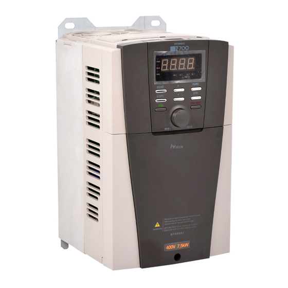
Page 19: Appearance
N700E INSTRUCTION MANUAL Appearance 1.3.1 N700E-055LF/075LFP ~ N700E-220HF/300HFP Operator Front Cover Fig1-3 Appearance from the front Control circuit terminals Main circuit terminals Fig1-4 Front cover removed... -
Page 20: N700E-300Hf/370Hfp ~ N700E-1320Hf/1600Hfp
N700E INSTRUCTION MANUAL 1.3.2 N700E-300HF/370HFP ~ N700E-1320HF/1600HFP Operator Front Cover Fig1-5Appearance from the front Control circuit terminals Main circuit terminals Fig1-6Front cover removed... - Page 21 N700E INSTRUCTION MANUAL 1.3.3 N700E-1600HF/2000HFP ~ N700E 1600HF/2000HFP ~ N700E-2200HF/2500HFP Operator Front Cover Fig1-7Appearance from the front Control circuit terminals Main circuit terminals Fig1-8Front cover removed...
-
Page 22: N700E-2800Hf/3200Hfp ~ N700E-3500Hf/3800Hfp
N700E INSTRUCTION MANUAL 1.3.4 N700E-2800HF/3200HFP ~ N700E 2800HF/3200HFP ~ N700E-3500HF/3800HFP Operator Front Cover Fig1-9Appearance from the front Control circuit terminals Main Circuit Terminals Fig1-10Front cover removed... -
Page 23: Installation
N700E INSTRUCTION MANUAL 2. Installation and Wiring Installation Be sure to install the unit on flame resistant material such as metal. Otherwise, there is a danger of fire. Be sure not to place anything flammable in the vicinity. Otherwise, there is a danger of fire. Do not carry the unit by the top cover, always carry by supporting the base of unit. - Page 24 N700E INSTRUCTION MANUAL 2.1.1 Installation (1) Transportation This inverter has plastic parts. So handle with care. Do not over tighten the wall mounting fixings as the mountings may crack, causing is a risk of falling. Do not install or operate the inverter if there appears to be damaged or parts missing. Surface for the mounting of inverter The temperature of the inverter heatsink can rise very high.
- Page 25 N700E INSTRUCTION MANUAL (6) Mounting Position Mount the inverter in a vertical position using screws or bolts. The mounting surface should also be free from vibration and can easily hold the weight of the inverter. Fig 2-2Mounting Position (7) Ventilation within an Enclosure If you are installing one or more inverters in an enclosure a ventilation fan should be installed.
-
Page 26: Wiring
N700E INSTRUCTION MANUAL Wiring Be sure to ground the unit. Otherwise, there is a danger of electric shock and/or fire. Wiring work should be carried out by qualified electricians. Otherwise, there is a danger of electric shock and/or fire. Implement wiring after checking that the power supply is off. Otherwise, there is a danger of electric shock and/of fire. -
Page 27: Terminal Connection Diagram (Sink Type)
N700E INSTRUCTION MANUAL 2.2.1 Terminal Connection Diagram (sink type) Fig.2-3 Terminal Connection Diagram (sink type) - Page 28 N700E INSTRUCTION MANUAL (1) Explanation of main circuit Terminals Symbol Terminal Name Explanation of contents Connect alternating power supply. When using regenerative converter R,S,T (L1,L2,L3) Main power and RG series, don’t connect. U,V,W (T1,T2,T3) Inverter output Connect three-phase motor. Remove the short bar between PD and P, connect optional Power factor PD,P (+1,+) D.Creactor reactor (DCL).
- Page 29 N700E INSTRUCTION MANUAL Terminal Signal Terminal name Terminal function Symbol Contact rating: AC 250V2.5A Intelligent output terminal: (resistor load) Run status signal(RUN), Frequency arrival signal(FA1), 0.2A Output Set frequency arrival signal(FA2), (inductor load) signal DC 30V 3.0A Overload advance notice signal(OL), (resistor load) PID error deviation signal(OD), Alarm signal(AL) 0.7A...
-
Page 30: Main Circuit Wiring
When an EMC filter is to be installed, please contact your local HYUNDAI branch. In the case of two or more motors, install a thermal relay to each motor. - Page 31 N700E INSTRUCTION MANUAL When installing an external braking resistor make sure that the resistance is correctly rated to limit the current drawn through the BRD. ⑤ Regenerative breaking unit connection terminals (P,N) The Inverters rated more than 30KW don’t contain a BRD circuit. If regenerative braking is Required an external BRD circuit (Option) is required along with the resistor (Option) Connect external regenerative braking unit terminals (P,N) to terminals (P,N) on the inverter.
- Page 32 N700E INSTRUCTION MANUAL (2) Wiring of main circuit terminals The wiring of main circuit terminals for the inverter are in the following pictures. Width( Screw Wiring of terminals Corresponding type ㎜) Size N700E-055LF/075LFP N700E-075LF/110LFP (L1) (L2) (L3) (+1) (T1) (T2) (T3) 10.6 N700E-055HF/075HFP...
- Page 33 N700E INSTRUCTION MANUAL (+1) N700E-1600HF/2000HFP N700E-2200HF/2500HFP (L1) (L2) (L3) (T1) (T2) (T3) (+1) N700E-2800HF/3200HFP N700E-3500HF/3800HFP (L1) (L2) (L3) (T1) (T2) (T3) Table 2-3Wiring of main circuit terminals 2-11...
- Page 34 N700E INSTRUCTION MANUAL (3) Applicable Tools Note1 : The applicable equipment is for HYUNDAI standard four pole squirrel cage motor. Note2 : Be sure to consider the capacity of the circuit breaker to be used. Note3 : Be sure to use larger wire for power lines if the distance exceeds 20m.
- Page 35 N700E INSTRUCTION MANUAL (4) Common applicable tools External Applicable Tools Power lines resister Screw R,S,T Motor Electro- Torque Inverter between size Class Output U,V,W, Leak breaker magnetic model (N•m) P and (kW) P,PD,N (MCCB) Controller Terminal AWG,kcmil (MC) N700E- More than8 UCB100R HiMC32 055LF/075LFP...
- Page 36 N700E INSTRUCTION MANUAL External Applicable Tools Power lines resister Screw R,S,T Motor Electro- Torque Inverter between size Class Output U,V,W, Leak breaker magnetic model (N•m) P and (kW) P,PD,N (MCCB) Controller Terminal AWG,kcmil (MC) N700E- More than 8 UCB100R HiMC32 055LF/075LFP N700E- More than 8...
-
Page 37: Terminal Connection Diagram
N700E INSTRUCTION MANUAL 2.2.3 Terminal connection diagram (1) Terminal connection diagram ① The control circuit terminal of inverters is connected with the control board in unit. RXP RXN CM1 CM1 P24 FM AMI RN0 RN1 RN2 RN3 AL0 AL1 AL2 N700E #1 ~ #4 (5.5kW(HD) ~ 350kW(HD)) Fig 2-5Terminal connection diagram (2) Wiring... - Page 38 N700E INSTRUCTION MANUAL (3) Connection to the programmable logic controller output(sequencer) -J1(J3) : Selection switch for operating mode(Sink mode, Source mode) -J2(J4) : Selection of signal power source(Internal 24Vdc, External 24Vdc) - The connection to the input programmable logic controller (sequencer) Source Mode(Internal power supply) Source Mode(External power supply) Sink Mode(Internal power supply)
- Page 39 N700E INSTRUCTION MANUAL (4) Connection to the programmable logic controller input(sequencer) Fig 2-7 Output terminal and PLC connection (5) 2 communication RS-485 terminating resistor The termination resistorof the RS-485 communication is for purpose of preventingthe distortionand attenuationof the communication line and this resistor means the Impedance matching resistor in long- distance transport of RS-485 Data.The termination resistor is inserted only in the final stage in single line.
-
Page 40: Operation
N700E INSTRUCTION MANUAL 3. Operation WARNING Be sure not to touch the main terminal or to check the signal add or remove wires and/or connectors. Otherwise, there is a danger of electric shock. Be sure not to turn the input power supply on until after front case is closed. While the inverter is energized, be sure not to remove the front cover. - Page 41 N700E INSTRUCTION MANUAL CAUTION The cooling fins will have high temperature. Be sure not to touch them. Otherwise, there is a danger of getting burned. Low to high speed operation of the inverter can be easily set. Be sure to operate it after checking the tolerance of the motor and machine.
-
Page 42: Operating
N700E INSTRUCTION MANUAL Operating This inverter requires two different signals in order for the inverter to operate correctly. The inverter requires both an operation setting and a frequency setting signal. The following indicates the details of each method of operation and necessary instructions for operation. -
Page 43: Test Run
N700E INSTRUCTION MANUAL Test Run This is an example of a common connection. Please refer to 4.1 Digital Operator, for the detailed use of the digital operator. 3.2.1 To input the operation setting and the frequency setting from the terminal control Fig 3-1 Setting diagram from the terminal control (Procedure) -
Page 44: Operation Setting And The Frequency Setting From The Digital Operator
N700E INSTRUCTION MANUAL 3.2.2 Operation setting and the frequency setting from the digital operator (Remote operator is also same use.) Fig 3-2 Setting diagram from the digital operator (Procedure) (1) Please make sure that connection is right. (2) Turn the MCCB on to supply power to the inverter. (The LED "POWER"... -
Page 45: Parameter Code List
N700E INSTRUCTION MANUAL 4. Parameter Code List About Digital Operator 4.1.1 Name and contents of each part of Standard-type digital operator (1) Part name STOP/RESET Key This key is used for stopping the motor or resetting errors.(When either operator or terminal is selected, this key works. RUN LED PRG LED If the extension function b 15 is used,... - Page 46 N700E INSTRUCTION MANUAL ② Key Description in RPM...
- Page 47 N700E INSTRUCTION MANUAL ③ Extended function mode navigation map ④ Display description: When the inverter is turned on, one of the display group can appear according to the setting value of b30 (display code setting)
-
Page 48: Key Definition And Operation Of "Shift
N700E INSTRUCTION MANUAL 4.1.2 Key Definition and Operation of “SHIFT” Definition : The“SHIFT”function is enable to press both up and down key simultaneously. The left most 7- segment digit is blinked and if press store key, the blinked segment moves to the right digit. When the ‘store’ key is pressed, it moved to the right digits again. -
Page 49: Function List
N700E INSTRUCTION MANUAL Function List 4.2.1 Monitor Mode (d-group) Func- Name Description code Real-time display of output frequency to Output frequency monitor motor, from 0.00 to 400.0 Hz, "Hz" LED ON Real-time display of output current to motor, Output current monitor from 0.0 to 9999A, "A"... -
Page 50: Trip &Warningmonitor Mode (D-Group)
N700E INSTRUCTION MANUAL 4.2.2 Trip &Warningmonitor mode (d-group) Func- Name Description code Displays the current trip event ·Display method Alarm reason ↓ press the UP key Output frequency at alarm event ↓ press the UP/DOWN key Output current at alarm event ↓... -
Page 51: Basic Function Mode
N700E INSTRUCTION MANUAL 4.2.3 Basic Function Mode Run- Func- Name time Description Defaults code Edit Standard default target frequency that determines constant motor that deter-mines constant motor speed. setting range is 0.00 to 400.0Hz.(In the case of sensorless vector control, setting range is 0.00 to 300.0Hz.) (1) frequency setting from UP/DOWN key of digital operator. -
Page 52: Expanded Function Mode Of A Group
N700E INSTRUCTION MANUAL 4.2.4 Expanded Function Mode of A Group Run- Func- Name time Description Defaults code Edit Basic parameter settings Four options: select codes: 0..Keypad potentiometer Frequency command 1..Control terminal input (Multi-speedcommand 2..Standard operator method) 3..Remote operator(1 communication-RJ45) 4.. - Page 53 N700E INSTRUCTION MANUAL Run- Func- Name time Description Defaults code Edit Two options: select codes: 0--- start at start frequency 1--- start at 0Hz External frequency start pattern setting External frequency Range n = 1 to 8, where n = number ofsamples for sampling setting average Multi-speed Frequency Setting...
- Page 54 N700E INSTRUCTION MANUAL Run- Func- Name time Description Defaults code Edit Manual torque boost Sets the frequency of the V/F breakpoint 10.0% frequency setting A in graphfor torque boost.Range is 0.0 to 100.0% Two available V/F curves: three select codes: 0...
- Page 55 N700E INSTRUCTION MANUAL Run- Func- Name time Description Defaults code Edit Frequency-related Functions Sets a limit on output frequency less than the maximum frequency(A04). Range isfrequency lower limit(A39) to maximum frequency(A04)in units of 0.01Hz. Frequency upperlimit 0.00Hz setting Sets a limit on output frequency greater than zero. Frequencylower limit Range is 0.00 to frequency upper limit(A38) in units 0.00Hz...
- Page 56 N700E INSTRUCTION MANUAL Run- Func- Name time Description Defaults code Edit Automatic Voltage Regulation (AVR) Function Automatic (output) voltage regulation, selects from three type of AVR functions three option codes: 0... Constant ON A52 AVR function selection 1... Constant OFF 2...
- Page 57 N700E INSTRUCTION MANUAL Run- Func- Name time Description Defaults code Edit Set the characteristic curve of Acc1 andAcc2, two options:. 0 --- Linear 1 --- S-curve 2 --- U-curve A59 Acceleration curve selection Set the characteristic curve of dec1 and dec2, two options:.
- Page 58 N700E INSTRUCTION MANUAL Run- Func- Name time Description Defaults code Edit PID Control(Note4) Enables PID function and Feed Forward Function, three option codes: A70 PID Function selection 0..PID control disable 1..PID control enable 2..F/F control enable Displays the PID reference. If parameter A72 = 2, A71 PID Reference Used to adjust the PID reference from UP/DOWN key 0.00%...
- Page 59 N700E INSTRUCTION MANUAL Run- Func- Name time Description Defaults code Edit Two options : select codes A80 PID Output reverse 0..PID output reverse disable 1..PID outputreverse enable PID scale factor (multiplier), A81 PID scale factor 100.0% 0.1 to 1000% in units of 0.1% 0.0 to Max Frequency(A04) in units of 0.01Hz.
- Page 60 N700E INSTRUCTION MANUAL The figure below is a more detailed diagram of the PID control. A01 Frequency Source Frequency Command 0 : Potentiometer 1 :Analog input 2 : Keypad C01~C06 : 23(PIDD) 3 : Remote PID Feed-back source CurFreq < PrePID Freq ACC/DEC PID Function selection PID output reverse...
- Page 61 N700E INSTRUCTION MANUAL Note 5:Pre-PID The Pre PID function is activated in Function code A82 (Pre PID Frequency). When the run signal comes, the inverter operates in the form of Open loop. If the output frequency reaches the Pre PID Frequency, it operates in Closed loop (PID control).
-
Page 62: Expanded Function Mode Of B Group
N700E INSTRUCTION MANUAL 4.2.5 Expanded function mode of b group Run- Func- Name time Description Defaults code Edit Restart Mode Select inverter restart method, four option codes: 0..Alarm output after trip, no automatic restart 1..Restart at 0Hz 2..Resume operation after frequency matching 3.. - Page 63 N700E INSTRUCTION MANUAL Run- Func- Name time Description Defaults code Edit Overload Restriction Select overload or overvoltage restrictionmodes 0..Overload, overvoltage restriction modeOFF Overload overvoltage 1..Only overload restriction mode ON Restrictionmode selection 2..Only overvoltage restriction mode ON 3..Overload /overvoltage restriction mode ON HD : 180% Sets the level for overload restriction, between 20% and ND : 150%...
-
Page 64: Other Function
N700E INSTRUCTION MANUAL Run- Func- Name time Description Defaults code Edit Other Function Start frequency Sets the starting frequency for the inverteroutput, range is 0.50Hz Adjustment 0.50 to 10.00Hz in units of 0.01Hz Sets the PWM carrier frequency, range is Carrier frequency setting (Note7) (Note8) - Page 65 N700E INSTRUCTION MANUAL Run- Func- Name time Description Defaults code Edit Other Function In case of the lowerstarting current level during speed Voltage increase Level search motion on the basis of the motor rated current, 100% during Speed Search the increase level of the output voltage is set from 10 % to 300% In case of the higherstarting current level during speed Voltage decrease Level...
- Page 66 N700E INSTRUCTION MANUAL Run- Func- Name time Description Defaults code Edit A function that detects phase loss in the input AC source. Detection is performed using the fluctuation in the main circuit's DC voltage. Also,in the case of degradation in the main capacitor, this message could be occurred.
- Page 67 N700E INSTRUCTION MANUAL Footnotes for the preceding tables Note7:Carrier frequency factory setting in types of Inverter load and model. Model Heavy Duty (b26 = 0) Normal Duty (b26 = 1) N700E-055LF/075LFP~185LF/220LFP 5.0kHz 2.0kHz N700E-055HF/075HFP~185HF/220HFP N700E-220LF 3.0kHz 2.0kHz N700E-220HF/300HFP~1320HF/1600HFP N700E-1600HF/2000HFP~3500HF/3800HFP 2.0kHz 2.0kHz ※By setting up b26=1, All models have the same carrier frequency2.0kHz.
- Page 68 N700E INSTRUCTION MANUAL Table 4-1 The relay operation(“AL”mode) and restart in case of overvoltage trip and overcurrent trip. b24=0 b24=1 b24=2 b24=3 (The alarm relay (The alarm relay (The alarm relay active (The alarm inactiveoperation activeoperation operation in case of all relayactiveoperation in case of low in case of low...
- Page 69 N700E INSTRUCTION MANUAL Table 4-2The relay operation(“AL”mode) and restart in case ofundervoltage trip b24=2 b24=0 b24=1 b24=3 (The alarm relay (The alarm relay (The alarm relay (The alarm active operation in inactiveoperation activeoperation relayactiveoperation case of all failure in case of low voltage in case of low incase of VFD occurred including...
-
Page 70: Expanded Function Mode Of C Group
N700E INSTRUCTION MANUAL 4.2.6 Expanded Function Mode of C Group Run- Func- Name time Description Defaults code Edit Input Terminal Function Select function for terminal 1 <code> 0: Forward run command(FW) 1 : Reverse run command(RV) 2 : 1st multi-speed command(CF1) 3 : 2nd multi-speed command(CF2) 4 : 3rd multi-speed command(CF3) 5 : 4th multi-speed command(CF4) - Page 71 N700E INSTRUCTION MANUAL Run- Func- Name time Description Defaults code Edit Input Terminal Status Select logic convention, two option codes: Input Terminal 1 a/b contact 0..normally open [NO] setting(NO/NC) 1..normally closed [NC] Select logic convention, two option codes: Input Terminal 2 a/b contact 0..
- Page 72 N700E INSTRUCTION MANUAL Run- Func- Name time Description Defaults code Edit Select logic convention, two option codes: Output Terminal RN2-RN3 0..a contact(normally open) [NO] a/b contact setting 1..b contact(normally closed) [NC] Select function for terminal FM, 3 options 0..
- Page 73 N700E INSTRUCTION MANUAL Run- Func- Name time Description Defaults code Edit Select function for terminal FM, 3 options 0..output frequency monitor 1..output current monitor AMI output selection 2..output voltage monitor 3..output power monitor C26 AMI gain adjustment Range is 0 to 250.0, resolution is 1 100.0% C27 AMI offset adjustment...
-
Page 74: Expanded Function Mode Of H Group
N700E INSTRUCTION MANUAL 4.2.7 Expanded Function mode of H Group Run- Func- Name time Description Defaults code Edit Two States for auto-tuning function, option codes: H01 Auto-tuningmode selection 0..Auto-tuning OFF 1..Auto-tuning ON Two selections, option codes: H02 Motor data selection 0…Use standard motor data 1…Use auto-tuning data 2.2H : 380V / 2.2kW... -
Page 75: Using Intelligent Terminals
N700E INSTRUCTION MANUAL 5. Using intelligent terminals Intelligent terminal lists Terminal Terminal Description symbol name SWF switch Forward ON(closed) :Forward RUN/STOP terminal OFF(open) : stop SWR switch Reverse ON(closed) :Reverse RUN/STOP terminal OFF(open) :stop Multi-speed frequency commanding terminal Jogging Jogging operation 2-stage The acceleration or deceleration time is possible to change considering acceleration... - Page 76 N700E INSTRUCTION MANUAL Terminal Terminal Description symbol name Local Keypad Frequency command is changed to the keypad potentiometer (like as A01 = 0) and (20) Operation Run command is changed to Standard Operator (like as A02 = 0). Local Terminal Frequency command is changed to the control terminal input (like as A01 = 1) and (21) Input Operation...
- Page 77 N700E INSTRUCTION MANUAL Terminal Terminal name Description symbol When the [RUN] signal is selected, the inverter Run signal outputs a signal on that terminal when it is in the RUN mode. Frequency arrival [FA1][FA2] signals is indicated when the output frequency accelerates and decelerates to arrive at a constant frequency.
-
Page 78: Monitor Terminal Function
N700E INSTRUCTION MANUAL Monitor terminal function Monitor terminal function [FM] (analog) • The inverter provides an analog output terminal primary for frequencymonitoring on terminal [FM] (output frequency, Output current, output voltage and output power monitor signal). •Parameter C18 selects the output signal data. When using the analog motor for monitoring, use scale reactor C19 and C20 toadjust the [FM] output so that the maximum frequency in the inverter corresponds to full-scale reading on the motor. - Page 79 N700E INSTRUCTION MANUAL Monitor terminal function [AMI] (analog) • The inverter provides an analog output terminal primary for frequencymonitoring on terminal [AMI] (output frequency, Output current, output voltage monitor signal). •Parameter C25 selects the output signal data. When using the analog motor for monitoring, use scale reactor C26 and C27 toadjust the [AMI] output so that the maximum frequency in the inverter corresponds to full-scale reading on the motor.
-
Page 80: Intelligent Input Terminal Function
N700E INSTRUCTION MANUAL Intelligent Input Terminal Function Forward Run/Stop [FW] and Reverse Run/Stop Command [RV] • When you input the Run command via the terminal [FW], the inverter executes the Forward Runcommand (high) or Stop command(low) • When you input the Run command via the terminal [RV], the inverter executes the Reverse Run command(high) or Stop command(low). - Page 81 N700E INSTRUCTION MANUAL Multi-Speed Select [CF1][CF2][CF3][CF4] • The inverter provides storage parameters for up to 16 different target frequencies (speeds) that the motor output uses for steady-state run condition. These speeds are accessible through programming four of the intelligent terminals as binary-encoded inputs CF1 to CF4 per the table .
- Page 82 N700E INSTRUCTION MANUAL Control circuit terminal Multi-speed Set code Speed 0 Speed 1 Speed 2 Speed 3 Speed 4 Speed 5 Speed 6 Speed 7 Speed 8 Speed 9 Speed 10 Speed 11 Speed 12 Speed 13 Speed 14 Speed 15...
- Page 83 N700E INSTRUCTION MANUAL Standard operator option code Set the parameter [ C01~ C06 ] to [ A11 ~ A25 ], F01 Option Terminal Function Name State Description Code Symbol Valid for inputs: C01,C02,C03,C04,C05,C06 Example: Required setting F01, A11 to A25 Notes : •...
- Page 84 N700E INSTRUCTION MANUAL Jogging Command [JG] [JG] Terminal •When the terminal [JG] is turned on and the Run command is issued, the inverter [FW,RV] outputs the programmed jog frequency to the motor. Use a switch between (A27) terminals [CM1] and [P24] to activate Moter the JG frequency.
- Page 85 N700E INSTRUCTION MANUAL S to p Jogging Command [Communication] J o g -R W • When the Rs-485 communication be using, jog function also can use as communication without terminals. J o g -F W • The frequency for the jogging operation is M o te r set by parameter A26.
- Page 86 N700E INSTRUCTION MANUAL [FW,RV] Two-stage Acceleration and Deceleration [2CH] [2CH] •When terminal [2CH] is turned on, the inverter changes the rate of acceleration and deceleration from the initial settingsF02 (acceleration time1) andF03(deceleration time1) Output to use the second set of acceleration / deceleration values. frequency time •When the terminal is turned off, the equipment is turned off,...
- Page 87 N700E INSTRUCTION MANUAL Free-run stop [FRS] •When the terminal [FRS] is turned on, the inverter stops the output and the motor enters the free-run state (coasting). If terminal [FRS] is turned off, theoutput resumes sending power to the motor if the Run command is still active.
- Page 88 N700E INSTRUCTION MANUAL External Trip [EXT] •When the terminal [EXT] is turned on, the inverter enters the trip state, indicates error code, E12 and stop the output. This is a general purpose interrupt type feature, and the meaning of the error depends on what you connect to the [EXT] terminal.
- Page 89 N700E INSTRUCTION MANUAL Unattended Start Protection [USP] •If the Run command is already set when power is turned on, the inverter starts running immediately after power up. The Unattended Start Protection (USP) function prevents that automatic start up, so that the inverter will not run with-out outside intervention.
- Page 90 N700E INSTRUCTION MANUAL Software Lock [SFT] •When the terminal [SFT] is turned on, the data of all the parameters and functions except the output frequency is locked (prohibited from editing). When the data is locked, the keypad keys cannot edit inverter parameters. To edit parameters again, turn off the [SFT] terminal input.
- Page 91 N700E INSTRUCTION MANUAL Analog Input Current / Voltage Select [AT] •The [AT] terminal selects whether the inverter uses the voltage [O] or current[OI] input terminals for external frequency control. When the switch between the terminals [AT] and [CM1] is on, it is possible to set the output frequency by applying a current input signal at [OI]-[L].
- Page 92 N700E INSTRUCTION MANUAL Reset Inverter [RS] 12ms min •The [RS] terminal causes the inverter to execute the reset operation. If the inverter [RS]terminal is in Trip Mode, the reset cancels the Trip state. Approx.30ms When the switch between the set terminals [RS] and [CM1] is turned on and off, the inverter Alarm output executes the reset operation.
- Page 93 N700E INSTRUCTION MANUAL 3-Wire input function[STA,STP,F/R] •This function is used when a momentary push start/stop control is required. •Set the operation command selection A02 to control terminal (1). •Assign 15 (STA), 16 (STP) and 17 (F/R) to three of the intelligent input terminals, and the operation becomes possible as follows.
- Page 94 N700E INSTRUCTION MANUAL UP/DOWN Function [UP,DOWN] • The Inverter output frequency can be changed with the UP and DOWN intelligent input terminals. • Assign 18 (UP) and 19(DN)to two of the intelligent input terminals 1~6 •This function will not operate when the external analog frequency command or the jogging operation is used. •...
- Page 95 N700E INSTRUCTION MANUAL Local Keypad Operation [O/R],Local Terminal Input Operation [T/R] •In case of operation by other than using keypad or terminal, it can be changed to local keypad operation (O/R function (20)) or local terminal input (T/R function (21)) by the multi-function input for the purpose of conducting manual operation method change.
- Page 96 N700E INSTRUCTION MANUAL PID Integral Reset [PIDIR] • When the terminal [PID Integral Reset] is turned on, the accumulated Integralterm of the PID controller is reset. Option Terminal Input Function Name Description Code Symbol State The accumulated Integral term of the PID controller is reset to zero.
- Page 97 N700E INSTRUCTION MANUAL PID Disable [PIDD] • When the terminal [PID Disable] is turned on, the inverter operates without PID control. Setting the function code F01 can change the target frequency. When the terminal [PID Disable] is turned off, the inverter operates with PID control. Option Terminal Input...
-
Page 98: Using Intelligent Output Terminals
N700E INSTRUCTION MANUAL Using Intelligent output terminals output terminals Run Signal [RUN] When the [RUN] signal is selected as an intelligent output terminal, the inverter When the [RUN] signal is selected as an intelligent output terminal, the inverter outputs a signal on that outputs a signal on that terminal when it is in the Run Mode. - Page 99 N700E INSTRUCTION MANUAL Frequency Arrival Signal [FA1]/[FA2] Frequency Arrival [FA1] and [FA2] signals indicate when the output frequency accelerates or decelerates to arrive at a constant frequency.Refer to the figure below. Frequency Arrival [FA1](upper graph) turns on when the output frequency gets within 0.5Hz below or 1.5Hz above the target constant frequency.
- Page 100 N700E INSTRUCTION MANUAL Overload Advance Notice Signal [OL] When the output current exceeds a preset value, Motor current the [OL] terminal signal turns on. The parameter C21 sets the overload threshold. The overload detection circuit operates during powered motor operation and during regenerative braking. Over load The output circuits use relay output, signal output...
- Page 101 N700E INSTRUCTION MANUAL Output Deviation for PID Control [OD] Feedback value The PID loop error is defined as themagnitude(absolute value) Target value of the difference between the Set point (target value) and the PID control process Variable (actual value). When the error magnitude exceeds the press value for C24, the [OD] terminal signal turns on.
- Page 102 N700E INSTRUCTION MANUAL Alarm Signal output [AL] The Inverter alarm signal is active when a fault has occurred and it is in the Trip Mode. When the fault is cleared the alarm signal becomes inactive. We must make a distinction between the alarm signal [AL] and the alarm relaycontacts AL0, AL1and AL2. The signal [AL] is a logic function which you can assign to the relay output terminalRN0-RN1 and RN2-RN3.
-
Page 103: Alarm Terminal Function
N700E INSTRUCTION MANUAL Alarm Terminal Function Alarm Terminal [AL1, AL2-AL0] The alarm output terminals are connected as shown below by default, or after initialization. The relay contacts normally contact a. Convention uses "normal' to mean the inverter has power and is in Run or Stop Mode. The relay contacts switch to the opposite position when it is Trip Modeor when input power is off. -
Page 104: Sensorless Vector Control
N700E INSTRUCTION MANUAL Sensorless Vector Control Function description The N700E inverter has a built-in auto-tuning algorithm. The N700E inverter can be possible to do high-starting torque and high-precision operation. The required torque characteristic or speed control characteristic may not bemaintained in case that the inverter capacity is more than twice the capacity of the motor in use . -
Page 105: Function Description
N700E INSTRUCTION MANUAL Auto-tuning(1) Function description The auto-tuning procedure automatically sets the motor parameter related to sensorless vector control. Since sensorless vector control needs motor parameter, the standard motor parameters have been set at the factory. Therefore, when an inverter exclusive-use motor is used or when a motor of any other manufacture is drive, the motor parameter is detected by auto-tuning because the parameters are not matched. - Page 106 Auto-tuning process completed : Auto-tuning process failed : Note 1.The motor parameter of N700E is standard data of HYUNDAI standard 4-poles motor. At the sensorless vector control when using different poles motor, operates by using auto-tuning data as a motor parameter.
- Page 107 N700E INSTRUCTION MANUAL Setting Method (1) Digital panel Name Setting range Description Auto-tuning 0 : Auto-tuning OFF mode selection 1 : Auto-tuning ON 0 : Standard data Motor data setting 1: Auto-tuning data 2.2H : 380V / 2.2kW 3.7H : 380V / 3.7kW 5.5H : 380V / 5.5kW 7.5H : 380V / 7.5kW 2.2L : 220V / 2.2kW...
- Page 108 N700E INSTRUCTION MANUAL Remark 1. If satisfactory performance through auto-tuning cannot be fully obtained, please adjust the motor constants for the observed symptoms according to the table below. Operation Symptom Adjustment Parameter status When low frequency Slowly increase the motor constant R1 in relationto (a few Hz) torque is H08/H10 auto-tuning data within 1 to 1.2 times R1.
-
Page 109: Protective Function
N700E INSTRUCTION MANUAL 6. Protective function The various functions are provided for the protection of the inverter itself, butthey may also protection function when the inverter breaks down. Error Name Cause(s) Code When the inverter output current exceeds the rated current by more than Overcurrent approximately 200% duringthe motor locked or reduced in speed. - Page 110 N700E INSTRUCTION MANUAL Other display Contents Contents Display Display It is displayed when initialization of data is processing It is displayed when initialization of data is processing (It is not displayed when initialization of history isprocessing.) (It is not displayed when initialization of history isprocessing.) There is no data available (Trip history, PID feedback data) (Trip history, PID feedback data)
-
Page 111: Troubleshooting Tips
N700E INSTRUCTION MANUAL 7. Troubleshooting Tips Symptom/condition Probable Cause Countermeasure •Is the frequency command source A01 •Make sure the parameter A01 parameter settingCorrect? setting correct? •Is the Run command sourceA02 •Make sure the parameter A02 parameter settingcorrect? setting correct? •Check terminals R, S and T then •Is power being supplied to terminals U, V, and W R, S and T? - Page 112 N700E INSTRUCTION MANUAL Symptom/condition Probable Cause Countermeasure •Was power turned off after a parameter •Edit the data and press the Inverter edit but before pressing the store key? store key once No down- data is •Edits to data are permanently stored at •Wait six seconds or more before loadshave power down.
-
Page 113: Maintenance And Inspection
N700E INSTRUCTION MANUAL 8. Maintenance and Inspection Please read following safety messages before troubleshooting or performing maintenance on the inverter and motor system. DANGER •Wait at least five(5) minutes after turning off the input power supply before performing maintenance of an inspection. Otherwise, there is the danger ofelectric shock. -
Page 114: Spare Parts
N700E INSTRUCTION MANUAL We recommend that you stock spare parts to reduce down time, which include Spare parts Quantity Part description Symbol Note Used Spare 5.5KW(HD) ~ 55KW(HD) 7.5KW(ND) ~ 75KW(ND) 75KW(HD) ~ 132KW(HD) 90KW(ND) ~ 160KW(ND) Cooling FAN 160KW(HD)~220KW(HD) 200KW(ND)~250KW(ND) 280KW(HD)~350KW(HD) 320KW(ND)~375KW(ND) - Page 115 N700E INSTRUCTION MANUAL - Monthly and Yearly Inspection Chart Inspection Cycle Item Inspected Check for… Inspection Method Criteria Month Year Ambient temperature Extreme Ambient Thermometer, ∨ between -10 to 40℃, temperatures environment hygrometer non-condensing & humidity Abnormal Stable environment for ∨...
-
Page 116: General Inverter Electrical Measurements
N700E INSTRUCTION MANUAL General Inverter Electrical Measurements General Inverter Electrical Measurements The following table specifies how to meas The following table specifies how to measure key system electrical parameters. eters. The diagrams on the next page show The diagrams on the next page show inverter-motor systems the location of measurement points tion of measurement points for these parameters. -
Page 117: Rs485 Communication
N700E INSTRUCTION MANUAL 9. RS485 Communication The communication between inverter and external controller can be done through RS-485 by use of the modular connector(RJ-45) located in inverter control board. Function Initial Minimum Maximum Unit Description code Value Settingthe communication number 9600bps 3: Remote Operator(RJ-45) 2: Remote Operator(RJ-45) - Page 118 N700E INSTRUCTION MANUAL Communication sequence The communication sequence is as follows Frame start : Frame start is recognized by signal line data transmitted. Frame completion : Frame completion is recognized by no data during correspond 4, 5-character time. Frame 1: Transmit from external controller to inverter. Frame 2: Indication reflects from inverter to external controller Communication frame type and form External controller transmit frame...
- Page 119 N700E INSTRUCTION MANUAL External transmit frame Communication Order Parameter Data CRC Hi CRC Lo number Description Data size Specifications Target Inverter Communication Communication 1 byte 1~32 number number Command Frame type 1 byte 0x06 byte : Group Parameter Parameter 2 byte (Note1) byte : Index (Note 2)
- Page 120 N700E INSTRUCTION MANUAL Note1 :Parameter setting Basic parameter byte : Each group is setting Group byte Group byte 0x01 0x05 0x02 0x06 0x03 0x04 byte : Parameter number setting. Ex) The case of A60 parameter reading or writing byte : 0x03 byte : 0x3C Trip information Trip information is 4 parameter.(output frequency, output current, DC link voltage at trip occurs)
- Page 121 N700E INSTRUCTION MANUAL Note2 :Data value setting Data value is transmitted except decimal point. Ex1) Output frequency Parameter value Communication data Conversion hexadecimal byte : 0x17 60.0Hz 6000 byte : 0x70 Ex2) acc/dec time Parameter value Communication data Conversion hexadecimal byte : 0x00 10.0sec byte : 0x64...
- Page 122 N700E INSTRUCTION MANUAL 16bit CRC generation The step of CRC generation is as follows: 1. All of 16-bit register is 1.0xffff 2. The exclusive OR of 16-bit register and 8-bit register. 3. Shift right side 1bit 16-bit register 4. If the result of step 3 is 1, exclusive OR 16-bit register and 0xa001. 5.
-
Page 123: Specification
N700E INSTRUCTION MANUAL 10. Specification 10.1 Standard specification list (1) 200V Class Specifications(IP20) 055LF/ 075LF/ 110LF/ 150LF/ 185LF/ Inverter Model 220LF 075LFP 110LFP 150LFP 185LFP 220LFP Max. Applicable motor 18.5 (Note1) (4P, kW) 18.5 200V 11.1 15.6 22.2 26.3 31.2 Rated 240V 10.0... - Page 124 IP00 Footnotes for the preceding tables Note 1. The applicable motor refers to HYUNDAI standard 3-phase motor(4-pole). To use other motors, care must be taken to prevent the rated motor current(50/60Hz) from exceeding the rated output current of the inverter.
- Page 125 N700E INSTRUCTION MANUAL Inverter model Common specifications for all model Intelligent output terminal RUN(run status signal), FA1 (frequency arrival signal), (RN0-RN1,RN2-RN3) FA2 (setting Frequency arrival signal),OL(overload advance notice signal), OD(PID error deviation signal), AL(alarm signal) Alarm output terminal Analog meter (DC0~10V fullscale. Max ∙ 1mA) FM output Output frequency, output current, output voltage and output power Analog meter (4~20mA full scale.
-
Page 126: The Selection Of Braking Resistor And The Breakingunit
N700E INSTRUCTION MANUAL 10.2 The selection of braking resistor and the breakingunit Resistor values shown in the following table is calculated on the basis of 150% of rated braking torque, 5% ED Power rating of resistor should be doubled for resistor frequency 10% ED use. Additional braking unit should be installedfor above Recommended DB Resistors for the Rated Inverter Capacity (5% ED Inverter capacity... -
Page 127: Dimension
N700E INSTRUCTION MANUAL 10.3 Dimension (1) N700E-055LF/075LFP, N700E-075LF/110LFP, N700E-110LF/150LFP, N700E-055HF/075HFP, N700E-075HF/110HFP and N700E-110HF/150HFP model external dimension.(mm) (2) N700E-150LF/185LFP, N700E-185LF/220LFP, N700E-220LF, N700E-150HF/185HFP, N700E-185HF/220HFP, N700E-220HF/300HFPmodel external dimension.(mm) 10-5... - Page 128 N700E INSTRUCTION MANUAL (3) N700E-300HF/370HFP, N700E-370HF/450HFPmodel external dimension.(mm) 312 [W] 265 [W1] 4-Ф10 240 [W2] 2-10 (4) N700E-450HF/550HFP, N700E-550HF/750HFPmodel external dimension.(mm) 10-6...
- Page 129 N700E INSTRUCTION MANUAL (5) N700E-750HF/900HFP, N700E-900HF/1100HFPmodel external dimension.(mm) (6) N700E-1100HF/1320HFP, N700E-1320HF/1600HFPmodel external dimension.(mm) 10-7...
- Page 130 N700E INSTRUCTION MANUAL (7) N700E-1600HF/2000HFP, N700E-2200HF/2500HFPmodel external dimension.(mm) (8) N700E-2800HF/3200HFP, N700E-3500HF/3800HFPmodel external dimension.(mm) 806 [W] 3-Ф14 700 [W1] 395 [D] 3-14 10-8...
- Page 131 N700E INSTRUCTION MANUAL W(Width) H(Height) D(depth) ø Weight Model [mm] [mm] [mm] [mm] [mm] [mm] [mm] [kg] N700E-055LF/075LFP N700E-075LF/110LFP N700E-110LF/150LF N700E-150LF/185LF N700E-185LF/220LF N700E-220LF N700E-055HF/075HFP N700E-075HF/110HFP N700E-110HF/150HFP N700E-150HF/185HFP N700E-185HF/220HFP N700E-220HF/300HFP N700E-300HF/300HFP N700E-370HF/450HFP N700E-450HF/550HFP N700E-550HF/750HFP N700E-750HF/900HFP N700E-900HF/1100HFP N700E-1100HF/1320HFP N700E-1320HF/1600HFP N700E-1600HF/2000HFP N700E-2200HF/2500HFP N700E-2800HF/3200HFP 1020 N700E-3500HF/3800HFP 1020...
- Page 132 N700E INSTRUCTION MANUAL REVISION HISTORY TABLE ELECTRO ELECTRIC SYSTEMS The Data Revision contents Version No. of Issue First edition 11. 05. HHIS-WZ-PE-082(00) Spec. table change(10-1) 12. 01 HHIS-WZ-PE-082(01) DB Resistor information was added(10-2) Error fixed, Intelligent Input 12. 03 HHIS-WZ-PE-082(02) Drawing changed B Group function code changed 12.
Need help?
Do you have a question about the N700 Series and is the answer not in the manual?
Questions and answers