Table of Contents
Advertisement
Advertisement
Table of Contents

Related Manuals for Hyundai N300-P


Summary of Contents for Hyundai N300-P
-
Page 2: Hazardous High Voltage
N300-P INSTRUCTION MANUAL SAFETY For the Best Results with N300 Series inverter, read this manual and all of the warning sign attached to the inverter carefully before installing and operating it, and follow the instructions exactly. Keep this manual handy for your quick reference. - Page 3 WARNING :The user is responsible for ensuring that all driven machinery, drive train mechanism not supplied by HYUNDAI and process line material are capable of safe operation at an applied frequency of 150% of the maximum selected frequency range to the AC motor. Failure to do so can result in destruction of equipment and injury to personnel should a single point failure occur.
- Page 4 This equipment should be installed, adjusted, and serviced by qualified personal familiar with construction and operation of the equipment and the hazards involved. Failure to observe this precaution could result in bodily injury. 1. The power supply to N300-P inverter must meet these specifications a. Voltage fluctuation 10% or less.
- Page 5 N300-P INSTRUCTION MANUAL Conformity to the Low Voltage Directive (LVD) The protective enclosure must conform to the Low Voltage Directive. The inverter can conform to the LVD by mounting into a cabinet or by adding covers as follows. 1. Cabinet and Cover The inverter must be installed into a cabinet which has the protection degree of Type IP2X.
- Page 6 N300-P INSTRUCTION MANUAL UL Warnings and Cautions Manual for N300 series This auxiliary instruction manual should be delivered to the end user. 1. Wiring warnings for Electrical Practices and Wire Specifications WARNING : "Use 60/75 CU wire only" or equivalent.
- Page 7 N300-P INSTRUCTION MANUAL Tightening Torque [N m] Wire Range(AWG) Model Name N300-055HFP N300-075HFP N300-110HFP N300-150HFP N300-185HFP N300-220HFP N300-300HFP N300-370HFP N300-450HFP N300-550HFP N300-750HFP 250kcmil or 2 parallel of 1 AWG(75 ) N300-900HFP 13.7 250kcmil or 2 parallel of 1 AWG(75 ) N300-1100HFP 13.7...
- Page 8 N300-P INSTRUCTION MANUAL Circuit Breaker [A] Fuse [A] Model Name N300-055HFP N300-075HFP N300-110HFP N300-150HFP N300-185HFP N300-220HFP N300-300HFP N300-370HFP N300-450HFP N300-550HFP N300-750HFP N300-900HFP N300-1100HFP N300-1320HFP N300-1600HFP 4. Others WARNING : "Field wiring connection must be made by an UL Listed and CSA Certified closed- loop terminal connector sized for the wire gauge involved.
- Page 9 N300-P INSTRUCTION MANUAL Revision History Table The Date of Operation Manual Revision Contents lssue Number HHIS-WZ-PE-032(00) Initial Release of Manual July. 2003 The Modification of Parameter Initial Value. Feb. 2004 HHIS-WZ-PE-032(01)
-
Page 10: Safety Precautions
N300-P INSTRUCTION MANUAL SAFETY PRECAUTIONS 1. Installation CAUTION Be sure to install the unit on flame resistant material such as metal P.2-2 Otherwise, there is a danger of fire. Be sure not to place anything inflammable in the vicinity. Otherwise, there is a danger of fire. - Page 11 N300-P INSTRUCTION MANUAL SAFETY PRECAUTIONS 2. Wiring WARNING Be sure to ground the unit. P.2-9 Otherwise, there is a danger of electric shock and/or fire. Wiring work shall be carried out by electrical experts. Otherwise, there is a danger of electric shock and/or fire.
- Page 12 N300-P INSTRUCTION MANUAL SAFETY PRECAUTIONS 3. Control and operation WARNING While the inverter is energized, be sure not to touch the main terminal or to P.3-1 check the signal or put on/off wire and/or connector. Otherwise, there is a danger of electric shock.
- Page 13 N300-P INSTRUCTION MANUAL SAFETY PRECAUTIONS CAUTION Cooling fin will have high temperature. Be sure not to touch them. P.3-2 Otherwise, there is a danger of getting burned. Low to high speed operation of the inverter can be easily set. Be sure to operate it after checking the tolerance of the motor and machine.
-
Page 14: Table Of Contents
N300-P INSTRUCTION MANUAL Table of Contents TABLE OF CONTENTS Chapter 1 General Descriptions 1.1 Inspection upon Unpacking Inspection of the unit Instruction manual 1.2 Question and Warranty of the Unit Request upon asking Warranty for the unit 1.3 Appearance Appearance and Names of parts Chapter 2 Installation and Wiring 2.1 Installation... - Page 15 N300-P INSTRUCTION MANUAL Table of Contents 4.3.2 Function mode Output frequency setting, Operation direction, Selection with limits of operation direction, Frequency command selection Operation command selection, Selection no stop, Selection of stop key Adjustable time Base frequency Maximum frequency, Carrier frequency...
- Page 16 N300-P INSTRUCTION MANUAL Table of Contents RUN time / power ON time over (RNT / ONT), Zero speed signal (ZS) Alarm code output (AC0 - AC3) FM terminal AM terminal, AMI terminal, External thermistor Initialization setting Display selection Stabilized factor, Motor constant...
-
Page 17: Chapter 1 General Descriptions
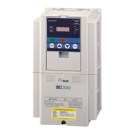
Picture 1-2 Contents of specification label 1.1.2 Instruction manual This instruction manual is the manual for the HYUNDAI Inverter N300-P Series. Before operation of the Inverter, read the manual carefully. After Reading this manual, keep it to hand for future reference. -
Page 18: Question And Warranty Of The Unit
If you have any questions regarding the warranty please contact either your supplier or the local HYUNDAI Distributor. Please refer to the back cover for a list of the local HYUNDAI Distributors. -
Page 19: Appearance Appearance And Names Of Parts
N300-P INSTRUCTION MANUAL Chapter 1 General Descriptions 1.3 Appearance 1.3.1 Appearance and Names of Parts Appearance from the front Power lamp Alarm lamp Digital operator Spacer cover Front cover Terminals cover Specifications Label Front cover removed Connector Installation point of self-contained option... - Page 20 N300-P INSTRUCTION MANUAL Chapter 1 General Descriptions 1.4 Application Method for J61 Connector Pin according to Input Power Grounding Condition 1.4.1 Usage of J61 Connector Pin and its application (1) Usage of J61 Connector Pin For N300 Inverter, a protection circuit is built-in case of lightning while being used, and it can be also protected when J61 Connector Pin is connected.
- Page 21 N300-P INSTRUCTION MANUAL Chapter 1 General Descriptions b) Features of Non-using J61 Connector Pin Although any transformer products are not grounded, there is little damage of Inverter due to no corruption in ZNR, as noise is intercepted from electric panel.
- Page 22 N300-P INSTRUCTION MANUAL Chapter 1 General Descriptions c) 30KW ~ 132KW Inverter Capacity (the same location as 200V Supply & 400V Supply) Location of J61 (2) Application Method of J61 Connector Sequencing of Application You should turn off the power, after halting Inverter working.
-
Page 23: Chapter 2 Installation And Wiring
N300-P INSTRUCTION MANUAL Chapter 2 Installation and Wiring 2.1 Installation CAUTION Be sure to install the unit on flame resistant material such as metal. Otherwise, there is a danger of fire. Be sure to place anything inflammable in the vicinity. - Page 24 N300-P INSTRUCTION MANUAL Chapter 2 Installation and Wiring 2.1.1 Installation 1. Transportation This inverter has plastic parts. So handle with care. Do not over tighten the wall mounting fixings as the mountings may crack, causing is a risk of falling.
- Page 25 N300-P INSTRUCTION MANUAL Chapter 2 Installation and Wiring 5. Operating Environment-Air Install the Inverter avoiding any place that has dust, corrosive gas, explosive gas, combustible gas, mist of coolant and sea damage. 6. Mounting Position Mount the Inverter in a vertical position using screws or bolts. The surface you mount onto should also be free from vibration and can easily hold the weight of the Inverter.
-
Page 26: Blind Cover Of Wiring Parts
N300-P INSTRUCTION MANUAL Chapter 2 Installation and Wiring 2.1.2 Blind cover of wiring parts (5.5 to 75kW) (1) Cable entry through Rubber Bushes The wiring should be done after making a cut in the rubber bushes with nippers or cutters. -
Page 27: Wiring
N300-P INSTRUCTION MANUAL Chapter 2 Installation and Wiring 2.2 Wiring WARNING Be sure to ground the unit. Otherwise, there is a danger of electric shock and/or fire. Wiring work shall be carried out by electrical experts. Otherwise, there is a danger of electric shock and/or fire. -
Page 28: Terminal Connection Diagram
N300-P INSTRUCTION MANUAL Chapter 2 Installation and Wiring 2.2.1 Terminal Connection Diagram (sink type) Power Source 3phase 200 240V 10%(50,60 POWER ALRAM HYUNDAI 8.8.8.8. 380 480V 10%(50,60 STOP/RESET BRD circuit: Short wire Installed on FUNC 5.5 to 15kW Shortbar Braking resistor... -
Page 29: Terminal Connection Diagram
N300-P INSTRUCTION MANUAL Chapter 2 Installation and Wiring 2.2.1 Terminal Connection Diagram (source type) Power Source 3phase 200 240V 10%(50,60 POWER ALRAM HYUNDAI 8.8.8.8. 380 480V 10%(50,60 STOP/RESET BRD circuit: Short wire Installed on FUNC 5.5 to 15kW Shortbar Braking resistor... - Page 30 N300-P INSTRUCTION MANUAL Chapter 2 Installation and Wiring (1) Explanation of main circuit terminals Symbol Terminal Name Explanation o f contents R,S,T Main power Connect alternating power supply. (L1,L2,L3) U, V, W Inverter output Connect three- phase motor. (T1,T2,T3) PD,P D.C reactor...
- Page 31 N300-P INSTRUCTION MANUAL Chapter 2 Installation and Wiring 2.2.2 Main circuit wiring (1) Warning on wiring When carrying out work on the Inverter wiring make sure to wait for at least ten minutes before you remove the cover. Making sure to check that the charge lamp is not illuminated.
- Page 32 N300-P INSTRUCTION MANUAL Chapter 2 Installation and Wiring 3. Direct current reactor (DCL) connection terminals (PD, P) These are the terminals to connect the current reactor DCL (Option) to help improve the power factor. The short bar is connected to the terminals when shipped from the factory, if you are to connect a DCL you will need to disconnect the short bar first.
- Page 33 N300-P INSTRUCTION MANUAL Chapter 2 Installation and Wiring (2) Wiring of main circuit terminals The wiring of main circuit terminals for inverter is the following picture. Wiring of terminals Corresponding type (L1) (L2) (L3) (T1) (T2) (T3) N300-055LFP/HFP N300-075LFP/HFP (+1)
- Page 34 Chapter 2 Installation and Wiring (3) Wiring Equipment Refer to "(4) Common applicable tools" (Note1) The applicable tools indicate for Hyundai standard four-pole squirrel-cage Motor (Note2) Select applicable tools for breakers examining the capacity of breakers. (Use Inverter type.) (Note3) Use earth-leakage breakers (MCCB) for safety.
- Page 35 N300-P INSTRUCTION MANUAL Chapter 2 Installation and Wiring (4) Common applicable tools Applicable Tools Motor Applicable Power External Screw Torque output Inverter lines resister size of (N.m) Electrom- (kw) Model R,S,T,U, between Terminal Leak breaker agnetic V,W,P, P-RB (MCCB) controller...
- Page 36 N300-P INSTRUCTION MANUAL Chapter 2 Installation and Wiring 5) Connecting power to the control circuit, separating from main power When the protection circuit of inverter is activated and the electromagnetic contactor on the input supply to the inverter isolates the power supply, the control circuit power supply from the inverter will also switch off and the alarm output signal will not be hold.
- Page 37 N300-P INSTRUCTION MANUAL Chapter 2 Installation and Wiring 2.2.3 Terminal connection diagram (1) Wiring 1. Both the CM1 and L terminal is insulated to both the common terminal of the input and output signals. Do not short or earth these common terminals.
- Page 38 N300-P INSTRUCTION MANUAL Chapter 2 Installation and Wiring (3) Change of input logic type The logic type of intelligent input terminals is written following list (Factory Default). N300-XXXLFP/HFP Sink type The input logic type can be changed by changing the Short bar connection of control terminal.
-
Page 39: Digital Operator Wiring
N300-P INSTRUCTION MANUAL Chapter 2 Installation and Wiring (5) The connection to the output programmable logic controller(sequency) 2.2.4 Digital operator wiring For operating this inverter, it can use digital operator OPE- SR, OPE-SRE, OPE-S, NOP3-0J, for remote operating, put off digital operator from inverter and use connector cable NOP3-1A(1.5m) or NOP3-3A(3m). -
Page 40: Chapter 3 Operation
N300-P INSTRUCTION MANUAL Chapter 3 Operation WARNING Be sure not to touch the main terminal or to check the signal or put on/off wire and/or connector. Otherwise, there is a danger of electric shock. Be sure to turn on the input power supply after closing from cover. - Page 41 N300-P INSTRUCTION MANUAL Chapter 3 Operation CAUTION Cooling fin will have high temperature. Be sure not to touch them. Otherwise, there is a danger of getting burned. Low to high speed operation of the inverter can be easily set. Be sure to operate it after checking the tolerance of the motor and machine.
- Page 42 This inverter requires two different signals in order for the inverter to operate correctly. The inverter requires both an operation setting and a frequency setting. The following indicates the details of each method of operation and necessary instructions for operation. (1) Operation setting and a frequency setting by the terminal control.
-
Page 43: Chapter 4 Explanation Of Function
N300-P INSTRUCTION MANUAL Chapter 4 Explanation of function Chapter 4 Explanation of function 4.3 Explanation of function 4.3.1 Monitor mode Output frequency monitor Relation code Indication code d001 displays the frequency the inverter outputs. d001 : Output frequency The data is displayed as follows. - Page 44 N300-P INSTRUCTION MANUAL Chapter 4 Explanation of function Intelligent input monitor The LED display will monitor the state of the intelligent inputs. Relation code d005 : Intelligent input (Example) monitor FW : Input intelligent terminal 7, 2, 1 : ON...
- Page 45 N300-P INSTRUCTION MANUAL Chapter 4 Explanation of function Frequency conversion monitor This inverter displays the value changed by the Inverter output ferquency and the valye set in b086 on the monitor part. "Monitor part of display" = "output frequency9d001)" x "output frequency factor(b086)"...
- Page 46 N300-P INSTRUCTION MANUAL Chapter 4 Explanation of function Accumulated time monitor on RUN The operation time of inverter is accumulated and the value is displayed. Relation code (Display) 0. - 9999. : Display is in 1 hour units. d016 : Accumulated time...
-
Page 47: Function Mode
N300-P INSTRUCTION MANUAL Chapter 4 Explanation of function Relation code 4.3.2 Function mode F001 : Output frequency setting Output frequency setting A001 : Frequency command Setting the output frequency of the motor. select The output frequency is set by F001, when frequency command... - Page 48 N300-P INSTRUCTION MANUAL Chapter 4 Explanation of function Operation command selection Relation code Select the control of RUN/STOP commands. A002 : Operation command selection Operation command from the control terminals (Teminal) C001-C008 : Intelligent input terminal Start/Stop by ON/OFF of control terminals.
- Page 49 N300-P INSTRUCTION MANUAL Chapter 4 Explanation of function Adjustable time Relation code The acceleration and deceleration time can be set. F002/F202/F302 : 1 /2 /3 acceleration time Set a long time to accelerate or decelerate slowly or F003/F203/F303 : 1 /2 /3 deceleration time set a short time to accelerate or decelerate quickly.
- Page 50 N300-P INSTRUCTION MANUAL Chapter 4 Explanation of function Base frequency Relation code Base frequency and motor voltage A003/A203/A303: 1 /2 /3 AVR function maximum frequency (1) Base frequency and motor voltage On selection of base frequency and motor voltage, set the output of the inverter (frequency voltage)
- Page 51 N300-P INSTRUCTION MANUAL Chapter 4 Explanation of function Maximum frequency Relation code Set the maximum frequency value of the inverter. A004/A204/A304: 1 /2 /3 This set value is the maximum frequency that the inverter will maximum frequency achieve when it receives top speed reference from the control terminals or the digital operator.
- Page 52 N300-P INSTRUCTION MANUAL Chapter 4 Explanation of function Relation code External analog input (0, 02, 01) This inverter has three kinds of external analog input terminals. A005 : AT terminal selection terminal : 0 - 10V A006 : 02 Selection...
- Page 53 N300-P INSTRUCTION MANUAL Chapter 4 Explanation of function Relation code External frequency Start / End A011 : O start A103 : OI start rate External analog signal from the control terminals A012 : O end A104 : OI end rate...
-
Page 54: Output Voltage Gain
N300-P INSTRUCTION MANUAL Chapter 4 Explanation of function Relation code Setting analog input filter Set the internal filter of the frequency setting signal of voltage or current A016 : O, O1, O2 filter from the control terminals It is important to first remove the source of the noise to the system. - Page 55 N300-P INSTRUCTION MANUAL Chapter 4 Explanation of function Relation code Control system (V/f Characteristic) A044/ A244/A344: 1 / 2 /3 control system Set V/f (output voltage/ output frequency) characteristic b001/b102/b104/b106/b108/b110/b112 To change 1 / 2 /3 control system (V/f characteristic),...
- Page 56 N300-P INSTRUCTION MANUAL Chapter 4 Explanation of function (3) Free V/f setting The free V/f setting optional V/f characteristics by setting the voltage and frequency in seven parts.(b001-b113) The setting of free V/f setting operates always to be 1 2 3 4 5 6 7.
-
Page 57: Torque Boost
N300-P INSTRUCTION MANUAL Chapter 4 Explanation of function Torque boost Relation code A correctly installed motor and careful attention to voltage A041/ A241 : 1 / 2 /3 torqrue boost selection A042/A242/A342:1 / 2 /3 manual operation torque drop in the wiring will improve the motor torque at low speed. - Page 58 N300-P INSTRUCTION MANUAL Chapter 4 Explanation of function Direct current braking(DB) Relation code A dc voltage can be applied to the motor windings A051:DC braking selectiond A056:DC braking edge/level in orde to lock the motor shaft and avoid overun A052:...
- Page 59 N300-P INSTRUCTION MANUAL Chapter 4 Explanation of function (2) Outside DC braking Set 07(DB) to an intelligent input terminal. DC braking is then switched by ON/OFF of DB terminal irrespective of DC braking selection A051. Set strength of DC braking power with A054.
- Page 60 N300-P INSTRUCTION MANUAL Chapter 4 Explanation of function (3) Inside DC braking When the inverter starts, and the DB terminal is not ON the inverter can operate dc braking. When using inside DC braking, the DC braking selection A 051 should be set 01.
- Page 61 N300-P INSTRUCTION MANUAL Chapter 4 Explanation of function Frequency limiter Relation code This function can set a maximum and minimum limit of the output frequency. A061/A261 : 1 / 2 frequency Even if a frequency command exceeds the maximum and minimum limiter maximum limiter the inverter will ignore this value and stop at the values set.
-
Page 62: Frequency Jump Function
N300-P INSTRUCTION MANUAL Chapter 4 Explanation of function Relation code Frequency jump function A063 : Jump frequency 1 Frequency jump can be used to avoid resonance points on machinery A064 : Jump frequency band 1 Frequency jump is to jump the frequency command and avoid usual A065 : Jump frequency 2 operation with the limit of the jump frequency. -
Page 63: Pid Function
N300-P INSTRUCTION MANUAL Chapter 4 Explanation of function PID function This integrated process control function can be used for controls such as constant flow and control for fan and pump applications. When using this function set A071 to 01. Turn off the terminal in the case that you validate... - Page 64 N300-P INSTRUCTION MANUAL Chapter 4 Explanation of function (4) The adjustment of gain Please adjust each according to the state as the follosing, when the response on the functional operation PID is not stable. Inspite of changing command, the change of feedback signal is slow.
- Page 65 N300-P INSTRUCTION MANUAL Chapter 4 Explanation of function Relation code Two-stage acceleration and deceleration function (2CH) F002/F202/F302 : 1 /2 /3 acceleration 1 By setting this function, it is possible to change the rate of F003/F203/F303 : 1 /2 /3 deceleration time 1 acceleration and deceleration .
- Page 66 N300-P INSTRUCTION MANUAL Chapter 4 Explanation of function Relation code Acceleration and deceleration pattern A097 : Acceleration pattern selection (1) Selection of pattern A098 : Deceleration pattern selection Pattern of acceleration and deceleration speed is A131 : Acceleration curve constant possible to set up corresponding to each system.
- Page 67 N300-P INSTRUCTION MANUAL Chapter 4 Explanation of function Relation code Instantaneous power failure / under-voltage b001 : Retry selection Instantaneous stop and start b002 : Allowable under-voltage power (1) You can select whether the inverter trips or retries(restart) failure time when an instantaneous power failure/under-voltage occurs.
- Page 68 N300-P INSTRUCTION MANUAL Chapter 4 Explanation of function (Note 1) When trip of the over voltage or over current etc.occurs in the deceleration midway an instantaneous power failure error (E16) is displayed and operates free-run. In this case make the deceleration time...
- Page 69 N300-P INSTRUCTION MANUAL Chapter 4 Explanation of function (2) Instantaneous power failure during stop alarm output during under-voltage Select yes/on of alarm output when instantaneous power failure or under-voltage occurs with b004. Alarm outputs while control power of inverter remains.
-
Page 70: Electronic Thermal Function
Data Electronic thermal characteristic cooling function of self-cooled fan will fall. Reduced torque characteristic Reduced torque characteristic is calculated according b013/b213/ to heat of an HYUNDAI general motor. constant torque characteristic b313 Free setting (a) Reduced torque charcteristic To add the time limit characteristic set with the reduced time rate b012/b212/b312 by each frequency. - Page 71 N300-P INSTRUCTION MANUAL Chapter 4 Explanation of function (b) Constant torque characteristic Set this in to use constant torque motor case. Reduced rated ratio (Example) b012=44(A), when output frequency = 2.5Hz Trip time(S) X1.0 X0.9 X0.8 Inverter output 0 2.5 5...
- Page 72 N300-P INSTRUCTION MANUAL Chapter 4 Explanation of function Relation code Overload restriction/Overload advance notice b021:Overload restriction selection (1) Overload restriction b022:Overload restriction level The Inverter monitors the motor current on acceleration and b023:Overload restriction constant constant speed, when the inverter reaches the overload restriction...
- Page 73 N300-P INSTRUCTION MANUAL Chapter 4 Explanation of function (2) Overload advance notice When the load is high, it is possible to adjust the again by outputting an overload advance notice. It is used to prevent damage to the machine from too much load, i.e. baggage on a conveyor, the Inverter overload protection will operate.
- Page 74 N300-P INSTRUCTION MANUAL Chapter 4 Explanation of function Relation code Start frequency b082:Start frequency This frequency is the value the operator must set before the Inverter will give an output. Mainly used when an operator adjusts the start torque. By setting the start frequency higher, direct starting is caused and the starting current increases.
- Page 75 N300-P INSTRUCTION MANUAL Chapter 4 Explanation of function Relation code BRD (dynamic braking) function b090:BRD use This function only operates with the N300-15kW and lower, as they have b095:BRD action selection the built-in BRD. This function is to consume regenerative energy from the motor as heat by b096:BRD on level the use of an external resistor.
- Page 76 N300-P INSTRUCTION MANUAL Chapter 4 Explanation of function Relation Intelligent input terminal setting It is possible to operate functions by assigning those functions to the C001 C008 : intelligent input terminals 1-8(C001-C008). Intelligent input terminal The intelligent input terminals 1-8 can be selected individually whether the contact input specification is either a NO or a NC contact.
- Page 77 N300-P INSTRUCTION MANUAL Chapter 4 Explanation of function Input terminal a/b(NO/NC)selection It is possible to set a contact input or b contact input to Relation code intelligent input terminals 1-8 and FW terminals individually. C011 C018 : Intelligent input Function...
- Page 78 N300-P INSTRUCTION MANUAL Chapter 4 Explanation of function (2) Bit operation It is possible to set multi-speed 0 to 7 by assigning 32 to 38 (SF1-SF7) to the intelligent input terminals. Set frequency SF1-SF7 to A021-A027. Multi- speed 0 speed...
- Page 79 N300-P INSTRUCTION MANUAL Chapter 4 Explanation of function Relation code Jogging operation (JG) A038 : Jogging frequency This function can be used to rotate the motor in small steps to allow A039 : Jogging selection fine-tuning. C001-C008 : Set an intelligent input terminal to 06 (JG).
- Page 80 N300-P INSTRUCTION MANUAL Chapter 4 Explanation of function Second/Third control function (SET, SET3) This control function is used when the Inverter is connected to two different types of motors. By assigning 08 (SET).17(SET3) to an intelligent input terminal and turning SET/SET3 terminal ON/OFF you can switech between three different inverter set-ups.
- Page 81 N300-P INSTRUCTION MANUAL Chapter 4 Explanation of function Relation code Software lock mode selection (SFT) b031 : Software lock mode selection This function is used to prevent changing data by mistake. C001-C008 : Intelligent input terminal When you want to use an intellignent input terminal, assign 15(SFT).
- Page 82 N300-P INSTRUCTION MANUAL Chapter 4 Explanation of function Relation code Free-run stop (FRS) b088 : Free-run stop selection By operating the free-run stop (FRS) function, the inverter output is cut off. b003 : Retry wait time The motor wills free wheel under its own mometum.
- Page 83 N300-P INSTRUCTION MANUAL Chapter 4 Explanation of function Relation code Commercial power source switching (CS) b003 : Retry waiting time This function is used for systems with an excessive amount of staring b007 : Frequency setting to torque requirements. The motor would be started direct-on-line and then...
- Page 84 N300-P INSTRUCTION MANUAL Chapter 4 Explanation of function Relation code Reset (RS) b003 : Retry waiting time This function resets the inverter when a protective trip has occurred. b007 : Frequency setting to match The method of reset is to either push the STOP/RESET key on the C102 : Reset selection digital operator or to switch the RS terminal ON.
- Page 85 N300-P INSTRUCTION MANUAL Chapter 4 Explanation of function Relation code Unattended start protection (USP) C001-C008 : Intelligent input terminal The USP function is designed as a fail safe to prevent accidental starting of the Inverter if the RUN signal is ON when the power is restored to the Inverter.
- Page 86 N300-P INSTRUCTION MANUAL Chapter 4 Explanation of function Relation code External trip (EXT) C001-C008 : Intelligent input terminal This function can be used to force the Inverter a trip situation which is Switched by an external input, i.e. PLC or relay contact.
- Page 87 N300-P INSTRUCTION MANUAL Chapter 4 Explanation of function Intelligent output terminal setting Any of the following functions can be assigned to the intelligent Relation code output terminals (11-15) or the alarm relay. C021-C025 : Intelligent output terminal Bothe intelligent output terminals 11 - 15 and the alarm relay are all...
- Page 88 N300-P INSTRUCTION MANUAL Chapter 4 Explanation of function Relation code Intellignet output terminal a/b (NO/NC) selection C031-C035 : Intelligent output 11-15 a/b This sets the intslligent output terminal 11-15 and alarm relay (NO/NC) selection output terminal contact condition to either NO or NC, (a or b).
- Page 89 N300-P INSTRUCTION MANUAL Chapter 4 Explanation of function Relation code Signal during run (Run) C021-C025 : Intelligent output terminal This function is to provide an output signal when the Inverter is in a running condition. Assign 00(RUN : signal during run) to an intelligent output terminal 11 -15 or the alarm relay output terminal.
- Page 90 N300-P INSTRUCTION MANUAL Chapter 4 Explanation of function (1) Output on constant speed arrival (01 : FA1) When the inverter arrives at the set frequency with frequency setting (F001, A220, A320) or multi-speed (A021-A035), the output relay is switched. Setting...
- Page 91 N300-P INSTRUCTION MANUAL Chapter 4 Explanation of function Relation code RUN time / power ON time over (RNT/ONT) b034 : Warning time level When the accumulated operation time reaches or is over the C021-C025 : Intelligent output terminal C026 : Alarm relay output terminal...
- Page 92 N300-P INSTRUCTION MANUAL Chapter 4 Explanation of function Relation code Alarm code output (AC0-AC3) C021-C025 : Intelligent output terminal This is the function that inverter outputs trip factor as signal. C062 : Alarm code selection When 01(3bit) or 02(4bit) is selected in alarm code selection, intelligent output terminal, 11-13 or 11-14 compulsorily is outputted in alarm code.
-
Page 93: Fm Terminal
N300-P INSTRUCTION MANUAL Chapter 4 Explanation of function Relation code FM terminal C027 : FM selection The FM control terminal can monitor the output frequency and output current. b081 : FM adjustment FM terminal is a PWM (Pulse Width Modeulation) output. - Page 94 N300-P INSTRUCTION MANUAL Chapter 4 Explanation of function Relation code AM terminal, AMI terminal b080 : AM adjustment The AM terminal and the AM1 terminal can monitor the output frequency C028 : AM selection or the output current. C029 : AMI selection The AM terminal has an analog output of 0-10V.
-
Page 95: Initialization Setting
N300-P INSTRUCTION MANUAL Chapter 4 Explanation of function Initialization setting Relation code It is possible at any time to reinitialize the inverter parameters back to b084 : Initialization selection their factory default. The trip history can also be cleared at any time,... -
Page 96: Display Selection
N300-P INSTRUCTION MANUAL Chapter 4 Explanation of function Relation code Display selection b037 : Display selection This function can be used to limit what the digital operator can display. U001-U012 : User selection Set item Data Description Function code All display... -
Page 97: Operation Selection On Option Error
N300-P INSTRUCTION MANUAL Chapter 4 Explanation of function Function to Code to be restricted display Data Note restrict display b120 Brake control b121~b126 02,06 C042,C043 Frequency arrival signal C040,C041 Overload advance notice C021~ C055~C058 over torque C025,C026 Zero speed detection signal... - Page 98 N300-P INSTRUCTION MANUAL Chapter 4 Explanation of function Fuzzy most suitable acceleration and deceleration Relation code Fuzzy acceleration and deceleration function eliminates setting of A044/A244/A344:1 /2 /3 control method acceleration and deceleration time in using inverter. A085 : Running mode selection...
-
Page 99: Braking Control Function
N300-P INSTRUCTION MANUAL Chapter 4 Explanation of function Relation code Braking control function b120 : Braking control selection This is a function that the inverter controls external braking used b121 : Waiting time for releasing braking in systems like elevators. By braking control function selection... - Page 100 N300-P INSTRUCTION MANUAL Chapter 4 Explanation of function b125 releasing frequency b125 releasing frequency Output frequency b123 waiting time for stop Running b121 waiting time for conformation command b122 waiting time for Braking releasing acceleration output Braking confirmation signal b124 waiting time fir braking...
- Page 101 N300-P INSTRUCTION MANUAL Chapter 4 Explanation of function Stopping deceleration at power OFF Relation code This is a function that decelerates and stops not to exceed over b050 : Selection of non-stop function at instantaneous power failure voltage level (OV-LADSTOP : b052) after power turns off during b051 : Starting voltage of non-stop function running.
-
Page 102: Motor Constant Selection
In 1 control method, it is possible to select setting range 00-02. In 1 control method, it is possible to select setting range 00-01. (Note 2) The second motor constant selection uses it with 00 (Hyundai standard motor constant). Optional setting of motor constant When motor constant is set optionally, function code is as the following below. -
Page 103: Communication Function
N300-P INSTRUCTION MANUAL Chapter 4 Explanation of function Relation code Communication function A001 : Frequency selection A002 : Operation command selection Serial communication i possible from the Inverter to any external C070 : Data command C071 : Communication transmission equipment using RS485 protocol. This function is built-in as standard speed and is controlled by the TM2 control terminals. - Page 104 N300-P INSTRUCTION MANUAL Chapter 4 Explanation of function Connect each inverter in parallel as shown below. It is necessary to short terminals RP and SN on the last inverter in the link(even if communication is to only one inverter the link should still be mabe) By shorting between RP and SN, the terminal resistance is increased and controls the reflection of the signal.
- Page 105 N300-P INSTRUCTION MANUAL Chapter 4 Explanation of function (3) Communication protocol The method the communication protocol is shown below in the time diagram. External control machines time Inverter C078 Waiting time (setting with operator) The following is indicated. (1) Frame transmitted from external control machines to the inverter.
- Page 106 N300-P INSTRUCTION MANUAL Chapter 4 Explanation of function Explanation of each command is the following. (i) 00 command : This controls the forward, backward and stop command. (Set yp A002 in 03 in the case that this command is used)
- Page 107 N300-P INSTRUCTION MANUAL Chapter 4 Explanation of function ( ) 02 command : This sets the state of the intelligent terminals. Transmission frame Frame format Code Command Data Explanation Data size Value Control code(Start of Text) 1 byte STX (0 02)
- Page 108 N300-P INSTRUCTION MANUAL Chapter 4 Explanation of function Frame format Code Command Explanation Data size Value Control code(Start of Text) 1 byte STX (0 02) 2 byte 01 32 Code Station number of inverter Transmission command 2 byte Command Exclusive OR of Code, Command and Data...
- Page 109 N300-P INSTRUCTION MANUAL Chapter 4 Explanation of function Transmission frame Frame format Code Command Explanation Data size Value Control code(Start of Text) 1 byte STX (0 02) 2 byte Code Station number of inverter 01 32 Transmission command 2 byte...
- Page 110 N300-P INSTRUCTION MANUAL Chapter 4 Explanation of function ( ) 05 command : This reads trip history data. Transmission frame Frame format Code Command Explanation Data size Value Control code(Start of Text) 1 byte STX (0 02) 2 byte Code...
- Page 111 N300-P INSTRUCTION MANUAL Chapter 4 Explanation of function ( ) 06 command : This returns 1 set item. Transmission frame Frame format Parameter Code Command Explanation Data size Value Control code(Start of Text) 1 byte STX (0 02) 2 byte...
- Page 112 N300-P INSTRUCTION MANUAL Chapter 4 Explanation of function ( ) 08 command : This returns each set value set value initial value. This works in conjunction with initial selection (b084). If b084 is 00, the trip history is cleared. Transmission frame...
- Page 113 N300-P INSTRUCTION MANUAL Chapter 4 Explanation of function ( ) OA command : This stores the set value to the EEPROM. Transmission frame Frame format Code Command Explanation Data size Value Control code(Start of Text) 1 byte STX (0 02)
- Page 114 N300-P INSTRUCTION MANUAL Chapter 4 Explanation of function (4) Acknowledge / Negative acknowledge response ( ) Acknowledge response Reply frame Frame format Code Explanation Data size Value 1 byte Control code(Start of Text) STX (0 02) 2 byte Code Station number of inverter...
- Page 115 N300-P INSTRUCTION MANUAL Chapter 4 Explanation of function (5) About the calculation of BCC (the Block Check Code) (Example) 5Hz is set up by using 01 command (the setting of the frequency command). (When the code of the inverter of the object is "01")
- Page 116 N300-P INSTRUCTION MANUAL Chapter 4 Explanation of function (6) Communication test mode The communication test mode checks the communication line of RS485. (The communication test mode procedure) ( ) Please remove the wiring of terminal unit TM2 of the control terminal unit foundation, to do the loop back check.
-
Page 117: Protection Function
N300-P INSTRUCTION MANUAL Chapter 4 Explanation of function 4.4 Protection function list 4.4.1 Protection function Display of remote µ ð Á ö Å Ð Display of operator /Copy unit Name Description ¿ À Æ Û · ¹ À Ì Å ¸... - Page 118 N300-P INSTRUCTION MANUAL Chapter 4 Explanation of function Display of remote Display of ¸ ® ¸ ð Æ ® operator /Copy unit ¿ À Æ Û · ¹ À Ì Å Í Item Contents digital panel ERR1*** E 36. When inverter cannot detect switching of the brake(ON/OFF) after...
- Page 119 N300-P INSTRUCTION MANUAL Chapter 4 Explanation of function Note 4) If the inverter doesn't run normally or the inverter trips, check the dip switch and/or rotary switch setting on optional board (1) Feed-back board (N-FB) DIP-SWITCH SWITCH NO. Contents Detection of disconnect A or B signal is valid Detection of disconnect A or B signal is invalid.
- Page 120 N300-P INSTRUCTION MANUAL Chapter 4 Explanation of function (3) Device Net option board(N-DN) The table below is the setting method of Baud rate (Front view of the option board) ( , indicate direction for switch of Dip switch) 125kbps 250kbps...
-
Page 121: Trip Monitor Display
N300-P INSTRUCTION MANUAL Chapter 4 Explanation of function 4.4.2 Trip monitor display (1) Factor of trip, explanation of display E07.2 E07.2 Display trip factor. Display the state of inverter on tripping 60.00 Please refer to 4.4.1 : During reset (2) Output frequency on trip (Hz) - Page 122 N300-P INSTRUCTION MANUAL Chapter 4 Explanation of function Relation code 4.4.3 Warning Monitor display d090 : Warning Monitor Warning message will appear when the data set is contradicting to others. Program lamp (PRG) turns ON during the warning (until the data is changed).
- Page 123 N300-P INSTRUCTION MANUAL Chapter 5 Maintenance, Inspection WARNING After a lapse of more than 10 minutes after tuning off the input power supply, perform the maintenance and inspection. Otherwise, there is a danger of electric shock. Make sure that only qualified persons will perform maintenance, inspection and part replacement.
-
Page 124: Daily Inspection And Regular Inspection
N300-P INSTRUCTION MANUAL Chapter 5 Maintenance, Inspection 5.2 Daily inspection and regular inspection Inspectioncycle Inspection Inspection Inspection Year Inspection methods Decision standard Meter Parts item item Temperature range is Thermometer, Check temperature between-10 and 40 hygrometer, Surroundings of surrounding, Refer to 2.1 Installing. -
Page 125: Megger Test
N300-P INSTRUCTION MANUAL Chapter 5 Maintenance, Inspection 5.3 Megger test When executing a megger test on the inverter remover all wires to R, S, T, PD, N, RB, U, V and W. Do not use a megger or buzzer on the control circuit only use a digital multi-meter. -
Page 126: The Method To Check Inverter, Converter Part
N300-P INSTRUCTION MANUAL Chapter 5 Maintenance, Inspection 5.5 The method to check Inverter, converter part A test is possible to check quality. (Preparation) [1] Take out the power lines (R, S and T0 connected to the inverter, the motor connection lines(U, V and W) and the regenerative control resistance (P and RB) [2] Prepare tester. -
Page 127: Capacitor Life Curve
N300-P INSTRUCTION MANUAL Chapter 5 Maintenance, Inspection 5.6 Capacitor Life Curve Ambient air temperature ( ) 12h/day operation 12h/day operation Life time(year) (Note 1) Ambient air temperature means the surrounding temperature of the inverter. In case the inverter is installed in a cabinet, ambient air temperature is the temperature of the internal air of the cabinet. -
Page 128: Standard Specification List
N300-P INSTRUCTION MANUAL Chapter 6 Specification 6.1 Standard specification list (1) 200V class N300- N300- N300- N300- N300- N300- N300- N300- N300- N300- N300- Inverter Model 055LFP 075LFP 110LFP 150LFP 185LFP 220LFP 300LFP 370LFP 450LFP 550LFP 750LFP Max. Applicadie 18.5... - Page 129 N300-P INSTRUCTION MANUAL Chapter 6 Specification (3) Common specification for 200V/400V class N300- N300- N300- N300- N300- N300- N300- N300- N300- N300- N300- N300- N300- N300- N300- Inverter Model 055LFP/HFP 075LFP/HFP 110LFP/HFP 150LFP/HFP 185LFP/HFP 220LFP/HFP 300LFP/HFP 370LFP/HFP 450LFP/HFP 550LFP/HFP 750LFP/HFP...
- Page 130 N300-P INSTRUCTION MANUAL Chapter 6 Specification 6.2 Dimension N300-055LFP/HFP N300-075HFP/HFP N300-110¡- 150LFP/HFP...
- Page 131 N300-P INSTRUCTION MANUAL Chapter 6 Specification N300-185 300LFP/HFP N300-370LFP/HFP...
- Page 132 N300-P INSTRUCTION MANUAL Chapter 6 Specification N300-450 550LFP/HFP N300-750HFP N300-750LFP...
- Page 133 N300-P INSTRUCTION MANUAL Chapter 6 Specification N300-900 1100HFP N300-1320 1600HFP...
Need help?
Do you have a question about the N300-P and is the answer not in the manual?
Questions and answers