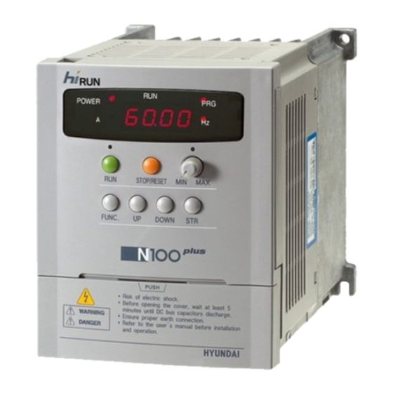
Sign In
Upload
Manuals
Brands
Hyundai Manuals
Inverter
N100 plus
Hyundai N100 plus Manuals
Manuals and User Guides for Hyundai N100 plus. We have
3
Hyundai N100 plus manuals available for free PDF download: Instruction Manual, Manual
Hyundai N100 plus Instruction Manual (126 pages)
VECTOR INVERTER
Brand:
Hyundai
| Category:
Inverter
| Size: 1.06 MB
Table of Contents
Table of Contents
2
Safety Messages
3
Definitions and Symbols
3
Installation-Cautions for Mounting Procedures
5
Specifications
7
Wiring-Cautions for Electrical Practices
8
Dangers for Operations and Monitoring
10
Cautions for Operations and Monitoring
12
Dangers and Cautions for Troubleshooting Inspection and Maintenance
13
Dangers for Using
13
Warning Display
14
Input Power Disconnection
15
Motor Terminal Surge Voltage Suppression Filter
15
Inverter Specifications Label
17
Model Number Convention
17
Receiving and Checking
17
N100 Inverter Standard Specifiations
18
200V Class Specifications
18
General Specifications
20
Footnotes for the Preceding Tables
22
Removing Terminal Cover
23
External Dimension Diagrams and Identifying the Parts
23
Main Physical Features
23
Inverter Dimensions for Mounting
25
Dimension Table by the Capacity
26
Installation
27
Choosing a Mounting Location
27
To Summarize the Cautions Messages
28
Wiring
29
Wiring the Main Circuit
30
Example of Control Circuit Terminal
32
Control Circuit Terminal
32
Wiring the Control Circuit
32
Connecting to Plcs
34
Application Wiring Apparatus & Options
35
Determination of Wire and Fuse Size
35
Standard Apparatus(3-Phase Input Reference)
36
Terminal Array & Terminal Function
38
Control Circuit
38
Main Circuit
38
Main Circuit Terminal
39
Terminal Function
39
Operation
41
Before the Powerup Test
42
Powerup Test
43
ACTION (Digital Operator Control)
43
Intelligent Terminal Lists
45
SWF Switch
45
SWR Switch
45
Using Intelligent Input Terminals
45
Output Current Monitor Signal
48
Terminal Name : Monitor Terminal [FM] (Analog)
48
Output Frequency Monitor Signal
48
Monitor Terminal Function
48
Intelligent Input Terminal Function
49
Multi-Speed Select
50
Standard Operator Option Code
52
Programming Using the CF Switches
52
Jogging Command [JG]
53
Second Control Function [SET]
54
Two-Stage Acceleration and Deceleration
55
Free-Run Stop [FRS]
56
External Trip [EXT]
57
Unattended Start Protection [USP]
58
Analog Input Current/Voltage Select [AT]
60
Reset Inverter [RS]
61
Software Lock[Sft]
62
Using Intellingent Output Terminals
63
Frequency Arrival Signal
63
Run Signal
65
Overload Advance Notice Signal
66
Output Deviation for PID Control [OD]
67
Alarm Signal Output [AL]
68
Alarm Terminal Function
69
Alarm Terminal
69
Contact Specification
69
Configuring the Inverter of Multiple Motors
70
Simultaneous Connections
70
Inverter Configuration for Two Motor Types
70
Sensorless Vector Control
71
Function Description
71
Function Setting Method
71
Auto-Tuning
72
Auto-Tuning Method
73
Digital Panel
74
Setting Method
74
Operating the Inverter
76
Identifying the Parts
76
Operation Procedure
76
Key Description
77
Expanded Function Mode Navigational Map
78
Display Description
78
Parameter Monitoring Functions
79
Function List
79
Basic Function Mode
81
Expanded Function Mode of a Group
82
Basic Parameter Settings
82
Analog Input Settings
82
Multi-Speed Frequncy Setting
83
V/F Characteristics
84
DC Braking Settings
85
Frequency-Related Functions
85
Automatic Voltage Regulation (AVR) Function
86
PID Control(Note1)
86
Second Acceleration and Deceleration Functions
87
PID Feedback Control
89
Input Method of Target Value Signal and Feedback Signal
89
PID Gain Adjustment
89
Expanded Function Mode of B Group
90
Restart Mode
90
Electronic Thermal Overload Alarm Setting
91
Overload Restriction
91
Other Function
92
Software Lock Mode
92
Expanded Function Mode of C Group
93
Input Terminal Function
93
Output Terminal Function
94
Output Terminal State Setting
95
Output Terminal Related Function
95
Expanded Function Mode of S Group
96
Expanded Function Mode of H Group
100
Protective Function
101
Other Display
102
Trouble Shooting Tips
103
Precautions for Data Setting
105
General Precautions and Notes
106
Maintenance and Inspection
106
Inspection Items
107
Spare Parts
107
Monthly and Yearly Inspection Chart
108
General Inverter Electrical Measurements
109
Three-Phase Measurement Diagram
110
Option
111
Dynamic Braking Resistor Table
111
Remote Operator
112
External Diagram
113
Remote Operator(NOP100)
113
Input-Side and Output-Side AC Reactor
114
Input - Side AC Reactor
115
Output-Side Reactor
115
Dimension of Input-Side AC Reactor for Power Pactor Correction
116
Dimension of Output-Side AC Reactor for Power Pactor Correction
116
Specification of the Noise Filter
117
Outlook of the Noise Filter
117
Connection of the Noise Filter
117
Noise Filter
117
RS485 Communication
118
Relation Code
118
Communication Formula
118
RS485 Port Specification
119
Communication Sequence
119
Communication Frame Type and Form
120
External Controller Transmit Frame
120
Inverter Response Frame
120
External Transmit Frame
121
Parameter Setting
122
Basic Parameter
122
Trip Information
122
Trip Information Items
122
Data Value Setting
123
Output Frequency
123
Special Parameter
123
Frequency Command
124
16Bit CRC Generation
124
The Sequence of Addition Byte
125
Advertisement
Hyundai N100 plus Instruction Manual (18 pages)
Inverter RS485 Interface
Brand:
Hyundai
| Category:
Inverter
| Size: 0.61 MB
Table of Contents
Instruction Manual
1
Table of Contents
2
1 RS485 Communication Function
3
Communication Function
3
Interface Cable Pin Arrangement
3
Interface Cable Pin Arrangement
4
RS485 Communication Specification
5
RS485 Communication Setting in Inverter
5
Communication Order
6
Communication Protocol
6
Inverter Read Frame
7
Request Frame for Setting Parameter
8
2 Example of Transmit/Receive Data Frame
13
Read Request & Response Data
13
A Prior Condition
13
Example 1 - Output Frequency Monitoring (Function Code : D01)
13
Example 2 - Output Frequency (Function Code : F01)
14
Example 3 - Acceleration Time (Function Code : F02)
14
Setting Request & Response Data
15
A Prior Condition
15
Output Frequency Setting (Function Code : F01)
15
Example 4 - Acceleration Time 1 Setting (F02)
15
Example 5 - Deceleration Time 1 Setting (F03)
15
Frequency Command
16
A Prior Condition
16
Example 6 - Frequency Command (in Case of 60Hz)
16
Example 7 - Frequency Command (in Case of 50Hz)
16
RUN Command Parameter
17
A Prior Condition
17
Example 8 - FWD(Forward) RUN Command
17
Example 9 - REV(Reverse) RUN Command
17
Example 10 - STOP Command
18
Hyundai N100 plus Manual (28 pages)
Brand:
Hyundai
| Category:
Inverter
| Size: 3.5 MB
Table of Contents
Table of Contents
3
Features
5
Operation
6
General Specifications
8
Function List
10
Terminal Functions
17
Protective Functions
18
Standard Connection Diagram
19
Application Wiring Apparatus & Options
20
Proper Operation
26
Advertisement
Advertisement
Related Products
Hyundai N100
Hyundai hiRUN N100-004SF
Hyundai hiRUN N100-007SF
Hyundai hiRUN N100-004LF
Hyundai hiRUN N100-007LF
Hyundai hiRUN N100-015LF
Hyundai hiRUN N100-022LF
Hyundai hiRUN N100-037LF
Hyundai hiRUN N100-004HF
Hyundai hiRUN N100-007HF
Hyundai Categories
Automobile
Car Receiver
Vacuum Cleaner
Excavators
Car Video System
More Hyundai Manuals
Login
Sign In
OR
Sign in with Facebook
Sign in with Google
Upload manual
Upload from disk
Upload from URL