Table of Contents
Advertisement
Quick Links
Advertisement
Table of Contents

Related Manuals for HikRobot CA Series


Summary of Contents for HikRobot CA Series
- Page 1 CA/CE-Series GigE Area Scan Camera User Manual...
- Page 2 WITHOUT LIMITATION, MERCHANTABILITY, SATISFACTORY QUALITY, OR FITNESS FOR A PARTICULAR PURPOSE. THE USE OF THE PRODUCT BY YOU IS AT YOUR OWN RISK. IN NO EVENT WILL HIKROBOT BE LIABLE TO YOU FOR ANY SPECIAL, CONSEQUENTIAL, INCIDENTAL, OR INDIRECT DAMAGES,...
- Page 3 TO ANY NUCLEAR EXPLOSIVE OR UNSAFE NUCLEAR FUEL-CYCLE, OR IN SUPPORT OF HUMAN RIGHTS ABUSES. THE PERFORMANCE DATA IN THIS PUBLICATION IS BASED ON HIKROBOT’S INTERNAL RESEARCH/EVALUATION. ACTUAL DATA MAY VARY DEPENDING ON SPECIFIC CONFIGURATIONS AND OPERATING CONDITIONS AND HIKROBOT SHALL NOT BEAR THE CONSEQUENCES ARISING THEREFROM.
- Page 4 CA/CE-Series GigE Area Scan Camera·User Manual 1. This device may not cause harmful interference. 2. This device must accept any interference received, including interference that may cause undesired operation. EU Conformity Statement This product and - if applicable - the supplied accessories too are marked with "CE" and comply therefore with the applicable harmonized European standards listed under the EMC Directive 2014/30/EU, LVD Directive 2014/35/EU, the RoHS Directive 2015/863/EU amending 2011/65/EU.
- Page 5 CA/CE-Series GigE Area Scan Camera·User Manual Safety Instructions These instructions are intended to ensure that the user can use the device correctly to avoid danger or property loss. Laws and Regulations The device should be used in compliance with local laws, electrical safety regulations, and fire prevention regulations.
- Page 6 The basic knowledge and operation skills of low voltage wiring and low voltage electronic circuit connection. The ability to comprehend the contents of this manual. Contact Information Hangzhou Hikrobot Technology Co., Ltd. No. 399 Danfeng Road, Binjiang District, Hangzhou, 310051, China...
- Page 7 CA/CE-Series GigE Area Scan Camera·User Manual E-mail: tech_support@hikrobotics.com Website: en.hikrobotics.com...
-
Page 8: Table Of Contents
CA/CE-Series GigE Area Scan Camera·User Manual Table of Contents Chapter 1 Overview ........................1 1.1 Appearance ........................1 1.2 Power and I/O Interface ....................2 1.3 Indicator Description...................... 3 Chapter 2 Camera Installation ......................4 2.1 Install Camera ........................ 4 Chapter 3 Camera Connection ...................... - Page 9 CA/CE-Series GigE Area Scan Camera·User Manual 7.5.1 Set Burst Frame Count ..................26 7.5.2 Set Trigger Delay ....................27 7.5.3 Set Trigger Cache Enable ..................28 7.5.4 Set Trigger Activation ..................29 7.5.5 Set Trigger Debouncer ..................30 7.6 Event Control ....................... 31 7.7 Chunk Data Control ......................
- Page 10 CA/CE-Series GigE Area Scan Camera·User Manual 10.12 Set White Balance ....................60 10.13 Set Gamma Correction ..................... 62 10.14 Set Hue and Saturation .................... 63 10.15 Set Sharpness......................65 10.16 Set AOI ........................65 10.17 Set LUT ........................66 10.18 Set Embedded Information in Image ................ 66 Chapter 11 Other Functions......................
-
Page 11: Chapter 1 Overview
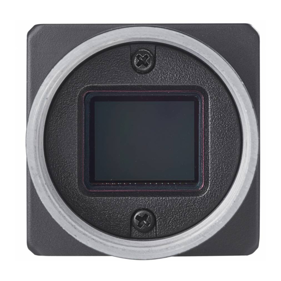
CA/CE-Series GigE Area Scan Camera·User Manual Chapter 1 Overview 1.1 Appearance The CA/CE-series GigE area scan camera possesses 3 kinds of appearance, with the same interface but slight interface position difference, as shown below. You should use M3 or M2 screw to install the camera to a position. -
Page 12: Power And I/O Interface
CA/CE-Series GigE Area Scan Camera·User Manual Figure 1-4 Interface (Type I) Table 1-1 Interface Description Description Lens mount 6-pin power and I/O interface M2 screw holes for securing network cable RJ45 Gigabit Ethernet interface LED indicator The CA/CE-series GigE area scan camera has 3 kinds of appearance, and here we take type I as an example for interface introduction. -
Page 13: Indicator Description
CA/CE-Series GigE Area Scan Camera·User Manual Signal I/O Signal Source Description Illustration Line 0, line 1 signal I/O Ground Signal ground ground Power ground and Power ground line 2 ground You should refer to the table above and the label attached to the power and I/O cable to wire the device. -
Page 14: Chapter 2 Camera Installation
CA/CE-Series GigE Area Scan Camera·User Manual Chapter 2 Camera Installation 2.1 Install Camera The area scan camera possesses 3 kinds of appearance, and here we take type I as an example for installation. Camera with different appearance may have different installation methods. The camera adopts a Gigabit network interface. -
Page 15: Chapter 3 Camera Connection
CA/CE-Series GigE Area Scan Camera·User Manual Chapter 3 Camera Connection 3.1 Install MVS Client Purpose: The MVS client is used to connect the camera, set its parameters, etc. The MVS client software is compatible with 32/64-bit Windows XP/7/10, 32/64-bit Linux, and 64-bit MacOS operating systems. -
Page 16: Set Network Interface Card
CA/CE-Series GigE Area Scan Camera·User Manual 3.2 Set Network Interface Card It is required to set the Jumbo packet and the Internet Protocol for the former can reduce the CPU usage and improve link efficiency, and the later ensures the connection between the device and the computer. -
Page 17: Set Camera Ip Address
CA/CE-Series GigE Area Scan Camera·User Manual 5. Click Apply to take the settings into effect. If you are not sure about the parameter functions, you can keep the cursor on the to view the parameter description. You can also set the Jumbo Packet and local network in the computer by accessing the NIC settings. -
Page 18: Connect Camera To Mvs
CA/CE-Series GigE Area Scan Camera·User Manual Figure 3-4 Modify IP Address 6. Edit the information, and click OK. You can modify the IP address of the device if its status is free. When switching between static IP and DHCP, the device will restart automatically. ... -
Page 19: Chapter 4 Live View
CA/CE-Series GigE Area Scan Camera·User Manual Chapter 4 Live View If the live view is normal, the camera is connected to the MVS. You can use the camera as you need. If not, please refer to the former steps and repeat again. After running the MVS client software, you can click to connect the camera, and then click to start acquisition, as shown below. -
Page 20: Chapter 5 Camera Settings
CA/CE-Series GigE Area Scan Camera·User Manual Chapter 5 Camera Settings 5.1 Main Window After connecting to the camera, the MVS client can read the camera attributes and display them in tree format. The main window and the description of the client are shown in Figure 5-1 and Table 5-1 respectively. -
Page 21: Set Parameters
CA/CE-Series GigE Area Scan Camera·User Manual Area Name Description Device Display the network interface information and the Information Panel device information. Display Window View the live video of the selected camera. View and configure features of the selected camera, and perform other operations such as importing, Feature Panel exporting, and saving features. - Page 22 CA/CE-Series GigE Area Scan Camera·User Manual Table 5-2 Attribute Description Attribute Description You can view device information, edit its name, reset the Device Control device, etc. You can view and set the device resolution, image Image Format Control reverse function, pixel format, region of interest, test pattern, etc.
- Page 23 CA/CE-Series GigE Area Scan Camera·User Manual Attribute Description Transport Layer You can set the parameters of transport layer of the Control device. You can save or load the device’s parameters. You can set User Set Control the default parameter when running the client. For specific attributes, please refer to the actual device you got.
-
Page 24: Chapter 6 Camera Features
CA/CE-Series GigE Area Scan Camera·User Manual Chapter 6 Camera Features 6.1 Global Shutter For camera that supports global shutter, its exposure starts and ends in each line simultaneously. After the exposure, data readout starts line by line. All pixels expose at the same time, then readout at different time, as shown below. -
Page 25: Rolling Shutter
CA/CE-Series GigE Area Scan Camera·User Manual Figure 6-3 Signal Readout under External Trigger Mode 6.2 Rolling Shutter For cameras that support rolling shutter: as soon as the exposure ends, and the data readout starts simultaneously. After the whole action, the rest of rows start to expose and read out one by one. All pixels expose at the same time, then readout at different time, as shown below. -
Page 26: Non-Overlap Exposure
CA/CE-Series GigE Area Scan Camera·User Manual 6.3.1 Non-Overlap Exposure After completing the current frame’s exposure and readout, the next frame starts to expose and read out. This process is called non-overlap exposure. The non-overlap exposure’s frame period is larger than the sum of the exposure time and the readout time, as shown below. ... - Page 27 CA/CE-Series GigE Area Scan Camera·User Manual Figure 6-7 Internal Trigger Overlap Exposure Overlap Exposure under External Trigger Mode Trigger_in 1 Trigger_in 2 Trigger_in 3 Exposure 1 Exposure 2 Exposure 3 Sensor exposure Frame 1 Frame 2 Readout Readout Figure 6-8 External Trigger Overlap Exposure The camera will ignore the external signal in the readout section under this mode.
-
Page 28: Chapter 7 Image Acquisition
CA/CE-Series GigE Area Scan Camera·User Manual Chapter 7 Image Acquisition 7.1 Set Frame Rate Frame rate refers to the image number that is acquired by the camera per second. The higher frame rate, and shorter time used for image acquisition will be. The following 4 factors determines the camera’s frame rate in real-time. -
Page 29: Set Acquisition Mode
CA/CE-Series GigE Area Scan Camera·User Manual If the current real-time frame rate is larger than configured frame rate, the camera acquires images according to the configured frame rate. 4. (Optional) Click Acquisition Control > Resulting Frame Rate to check the camera’s resulting frame rate, as shown below. -
Page 30: Set Trigger Mode
CA/CE-Series GigE Area Scan Camera·User Manual 7.3 Set Trigger Mode The camera has 2 types of trigger mode, including internal trigger mode and external trigger mode. The trigger mode principle and parameter setting are shown below. Table 7-1 Trigger Mode Principle and Parameter Trigger Mode Parameter Parameter Value... -
Page 31: External Trigger Mode
CA/CE-Series GigE Area Scan Camera·User Manual 7.4 External Trigger Mode 7.4.1 Set External Trigger Source There are 5 types of external trigger sources, including software trigger, hardware trigger, counter trigger, action command trigger, and anyway. Their principle and parameter setting are shown below. -
Page 32: Set Software Trigger
CA/CE-Series GigE Area Scan Camera·User Manual Figure 7-5 Set External Trigger Source These 5 external trigger sources are valid only when the Trigger Mode is On. 7.4.2 Set Software Trigger You can set software trigger as shown below. Steps: 1. Click Acquisition Control > Trigger Selector. 2. -
Page 33: Set Counter Trigger
CA/CE-Series GigE Area Scan Camera·User Manual Steps: 1. Click Digital IO Control. 2. Select Line 2 as Line Selector, and Input as Line Mode. Figure 7-7 Set Line2 as Input Signal 3. Select Line 0, or Line 2 as Trigger Source. Here we take Line 0 as an example. Figure 7-8 Set Hardware Trigger 7.4.4 Set Counter Trigger The counter trigger provides frequency division to the external trigger signal. - Page 34 CA/CE-Series GigE Area Scan Camera·User Manual Figure 7-9 Set Counter Trigger When using counter as trigger source, you need to set relevant parameters under Counter And Timer Control. For specific parameter function and setting, please refer to the following table. Table 7-3 Description of Counter And Timer Control Parameter Read/Write...
-
Page 35: Set Action Command Trigger
CA/CE-Series GigE Area Scan Camera·User Manual Figure 7-10 Counter Trigger Parameters 7.4.5 Set Action Command Trigger When you need to use the function of action commands, you should set action command trigger first. Steps: 1. Click Acquisition Control > Trigger Selector. 2. -
Page 36: Trigger Related Parameters
CA/CE-Series GigE Area Scan Camera·User Manual Steps: 1. Click Acquisition Control > Trigger Selector. 2. Select Frame Burst Start as Trigger Selector, and On as Trigger Mode. 3. Select Anyway as Trigger Source. Figure 7-12 Set Anyway Trigger 7.5 Trigger Related Parameters Under external trigger mode, you can set burst frame count, trigger delay, trigger cache enable, trigger activation and trigger debouncer. -
Page 37: Set Trigger Delay
CA/CE-Series GigE Area Scan Camera·User Manual Steps: 1. Click Acquisition Control > Acquisition Burst Frame Count. 2. Enter proper value according to actual demands. Its range is from 1 to 1023. Figure 7-13 Set Burst Frame Count When Acquisition Burst Frame Count is 1, it is in single frame trigger mode. When Acquisition Burst Frame Count is larger than 1, it is in multi-frame trigger mode. -
Page 38: Set Trigger Cache Enable
CA/CE-Series GigE Area Scan Camera·User Manual You can set proper value in Trigger Delay, and its range is from 0 μs to 16000000 μs. Figure 7-16 Set Trigger Delay 7.5.3 Set Trigger Cache Enable The camera has the function of Trigger Cache Enable. During the triggering process, if the camera receives new trigger signal, it will save and process the signal if you enable this function. -
Page 39: Set Trigger Activation
CA/CE-Series GigE Area Scan Camera·User Manual If the 1st frame image’s exposure time of the 2nd trigger signal is not earlier than the camera’s last frame creation time of the 1st trigger signal, and then the 2nd trigger signal’s 1st frame image is created normally. -
Page 40: Set Trigger Debouncer
CA/CE-Series GigE Area Scan Camera·User Manual You can set trigger activation as shown below. Steps: 1. Click Acquisition Control > Trigger Activation. 2. Select Rising Edge, Falling Edge, Level High or Level Low as Trigger Activation. Figure 7-18 Set Trigger Activation 7.5.5 Set Trigger Debouncer The external trigger input signal of the camera may have signal bounce that may cause false trigger. -
Page 41: Event Control
CA/CE-Series GigE Area Scan Camera·User Manual 2. Enter proper value in Line Debouncer Time, and its range is from 1 μs to 1000000 μs. Figure 7-20 Set Trigger Debouncer 7.6 Event Control The event control function allows you to enable event messages and camera events like Acquisition Start. -
Page 42: Action Commands
CA/CE-Series GigE Area Scan Camera·User Manual 2. Enable Chunk Mode Active. 3. Select specific parameters in Chunk Selector according to actual demands. 4. Enable Chunk Enable. Figure 7-22 Set Chunk Data Control 7.8 Action Commands The Action Command is used to trigger actions in multiple cameras in a network simultaneously. When Action Command is configured, the client can send commands across the network and have devices in a pre-defined group respond based on how they have been configured to respond to certain commands. - Page 43 CA/CE-Series GigE Area Scan Camera·User Manual Figure 7-23 Set Action Command Table 7-6 Parameter Description Parameter Requirement Its value should be the same with the value of the Device Key ActionDeviceKey feature. Its value should be the same with the ActionGroupKey Group Key feature.
-
Page 44: Color Transformation Control
CA/CE-Series GigE Area Scan Camera·User Manual 7. (Optional) Enable Periodically Send to enable the client to send commands periodically. 8. (Optional) Enter proper value in Sending Interval. The default value is 1000 ms, and valid value range is from 1 ms to 3600000 ms. 9. -
Page 45: Chapter 8 I/O Output
CA/CE-Series GigE Area Scan Camera·User Manual Chapter 8 I/O Output 8.1 Select Output Signal The camera has 1 opto-isolated output (Line 1), and 1 bi-directional I/O (Line 2) that can be configured as output signal, as shown below. Steps: 11. Click Digital IO Control. 12. -
Page 46: Enable Strobe Signal
CA/CE-Series GigE Area Scan Camera·User Manual The Line Inverter parameter is disabled by default. 8.2.2 Enable Strobe Signal The strobe signal is used to directly output I/O signal to external devices when camera’s event source occurs. You can enable strobe signal as shown below. Steps: 1. - Page 47 CA/CE-Series GigE Area Scan Camera·User Manual Table 8-1 Line Source Name Description Exposure Start Active It refers to output one I/O edge signal when starting exposure. Acquisition Start It refers to output one I/O edge signal when starting Active acquisition. Acquisition Stop It refers to output one I/O edge signal when stopping Active...
- Page 48 CA/CE-Series GigE Area Scan Camera·User Manual Figure 8-4 Set Strobe Line Duration When the Strobe Line Duration value is 0, the strobe duration is equal to the exposure time. When the Strobe Line Duration value is not 0, the strobe duration is equal to Strobe Line Duration value. ...
- Page 49 CA/CE-Series GigE Area Scan Camera·User Manual Figure 8-5 Set Strobe Line Delay The sequence diagram of strobe line delay is shown below. Trigger_in 3 Trigger_in 2 Trigger_in 1 Trigger Trigger Trigger delay delay delay Strobe delay Duration Strobe Exposure Exposure Exposure Sensor exposure...
- Page 50 CA/CE-Series GigE Area Scan Camera·User Manual Figure 8-7 Set Strobe Line Pre Delay The sequence diagram of strobe line pre delay is shown below. Trigger_in 3 Trigger_in 2 Trigger_in 1 Trigger Trigger Trigger delay delay delay Duration Strobe Exposure Exposure Exposure Sensor exposure...
-
Page 51: Chapter 9 I/O Electrical Feature And Wiring
CA/CE-Series GigE Area Scan Camera·User Manual Chapter 9 I/O Electrical Feature and Wiring 9.1 I/O Electrical Feature 9.1.1 Line 0 Opto-isolated Input Circuit The Line 0 opto-isolated input circuit in camera I/O control is shown below. Figure 9-1 Line 0 Internal Circuit The maximum input current of Line 0 is 25 mA. -
Page 52: Line 1 Opto-Isolated Output Circuit
CA/CE-Series GigE Area Scan Camera·User Manual Parameter Name Parameter Symbol Value Input Rising Delay 2.6 μs Input Falling Delay 19.2 μs Make sure the input voltage is not from 1 VDC to 1.5 VDC as the electric status between these two values are not stable. -
Page 53: Line 2 Bi-Direction I/O Circuit
CA/CE-Series GigE Area Scan Camera·User Manual Table 9-2 Output Electric Feature Parameter Name Parameter Symbol Value Output Logic Level Low 575 mV Output Logic Level High 3.3 V Output Rising Time 8.4 μs Output Falling Time 1.9 μs Output Rising Delay 16.6 μs Output Falling Delay 3.6 μs... - Page 54 CA/CE-Series GigE Area Scan Camera·User Manual Line 2 Configured as Input With the condition of 100 Ω and 5 VDC, the logic level and electrical feature of configuring Line 2 as output are shown below. Figure 9-6 Input Logic Level Table 9-4 Electrical Feature of Line 2 Input Parameter Name Parameter Symbol...
- Page 55 CA/CE-Series GigE Area Scan Camera·User Manual External Voltage External Resistance VL (GPIO2) 1 KΩ 220 mV 12 V 1 KΩ 460 mV 24 V 1 KΩ 860 mV 30 V 1 KΩ 970 mV The maximum current is 25 mA and the output impedance is 40 Ω. When the voltage of external resistance (1KΩ) is pulled up to 5V, the logic level and electrical feature of configuring Line 2 as output are shown below.
-
Page 56: I/O Wiring
CA/CE-Series GigE Area Scan Camera·User Manual 9.2 I/O Wiring The camera has different appearance with varied models. Here we take type I camera as an example to introduce I/O wiring. For specific camera appearance, cable color and I/O wiring, please refer to the actual one you got. 9.2.1 Line 0 Wiring When the camera uses Line 0 as hardware trigger source, wirings are different with different external devices of input signal. -
Page 57: Line 1 Wiring
CA/CE-Series GigE Area Scan Camera·User Manual Camera Power Supply Switch Opt-Iso in I/O Ground Camera Power Ground GND of VCC GND of PWR Figure 9-10 Line 0 Connecting to a Switch 9.2.2 Line 1 Wiring When the camera uses Line 1 as output signal, wirings are different with different external devices. ... -
Page 58: Line 2 Wiring
CA/CE-Series GigE Area Scan Camera·User Manual 9.2.3 Line 2 Wiring As bi-direction I/O Circuit, Line 2 can be used as both input signal and output signal. Line 2 Configured as Input When the camera uses Line 2 as hardware trigger source, wirings are different with different external devices of input signal. - Page 59 CA/CE-Series GigE Area Scan Camera·User Manual Camera Power Supply Switch Bi-direction Camera Power Ground GND of PWR and VCC Figure 9-15 Line 2 Connecting to a Switch as Input Line 2 Configured as Output When the camera uses Line 2 as output signal, wirings are different with different external devices. ...
-
Page 60: Chapter 10 Image Parameter
CA/CE-Series GigE Area Scan Camera·User Manual Chapter 10 Image Parameter 10.1 Check Resolution Steps: 1. Click Image Format Control. 2. Check Width Max and Height Max. Width Max stands for the max. pixels per inch in width direction and Height Max stands for the max. pixels per inch in height direction. Figure 10-1 Check Resolution The camera displays the image with max. -
Page 61: Set Image Reverse
CA/CE-Series GigE Area Scan Camera·User Manual Figure 10-2 Set ROI The Width value plus Offset X value should not be larger than Width Max parameter value, Height value plus Offset Y value should not be larger than Height Max parameter value ... -
Page 62: Set Pixel Format
CA/CE-Series GigE Area Scan Camera·User Manual Figure 10-3 Set Image Reverse Figure 10-4 Image Reverse Comparison For different models of camera, the image reverse function may be different, please refer to the actual one you got. 10.4 Set Pixel Format The camera supports many pixel formats. -
Page 63: Set Test Pattern
CA/CE-Series GigE Area Scan Camera·User Manual Table 10-1 Byte Number of Different Pixel Formats Format Byte Number Mono 8, Bayer GB/GR/BG/RG 8 Bayer GR/GB/RG 12 Packed, Bayer BG/GR/RG 10 Packed, Mono 10 Packed, Mono 12 packed Bayer GR/GB/RG 12, Bayer BG/GR/RG 10, YUV 4:2:2 (YUYV), YUV4:2:2 (YUYV) Packed RGB 8, BGR 8 You can set pixel format as shown below. - Page 64 CA/CE-Series GigE Area Scan Camera·User Manual You can set test pattern as shown below. Steps: 1. Click Image Format Control > Test Pattern. 2. Set Test Pattern according to actual demands. Figure 10-6 Set Test Pattern The mono camera offers 4 test patterns, including Mono Bar, Checkboard, Oblique Mono Bar and Gradual Mono Bar.
- Page 65 CA/CE-Series GigE Area Scan Camera·User Manual Figure 10-9 Oblique Mono Bar Test Pattern Figure 10-10 Gradual Mono Bar Test Pattern Figure 10-11 Vertical Color Bar Test Pattern...
-
Page 66: Set Binning
CA/CE-Series GigE Area Scan Camera·User Manual Figure 10-12 Horizontal Color Bar Test Pattern For different models of camera, the test pattern may be different, please refer to the actual one you got. 10.6 Set Binning The purpose of setting binning is to enhance sensibility. With binning, multiple sensor pixels are combined as a single pixel to reduce resolution and improve image brightness. -
Page 67: Set Decimation
CA/CE-Series GigE Area Scan Camera·User Manual 10.7 Set Decimation The decimation feature allows you to reduce the number of sensor pixel columns or rows that are transmitted by the camera. This procedure is also known as "subsampling". It reduces the amount of data to be transferred and may increase the camera's frame rate. -
Page 68: Set Gain
CA/CE-Series GigE Area Scan Camera·User Manual Exposure Mode Parameter Parameter Value Principle Acquisition Control > Adjust the exposure time Continuous Continuous Exposure Auto continuously according to the image brightness. When the exposure mode is set as Once or Continuous, the exposure time should be within the range of Auto Exposure Time Lower Limit and Auto Exposure Time Upper Limit, as shown below. -
Page 69: Set Brightness
CA/CE-Series GigE Area Scan Camera·User Manual Gain Mode Parameter Parameter Value Principle adjusting, it will switch to Off Mode. Analog Control > Adjust the gain continuously Continuous Continuous Gain Auto according to the image brightness. When the Gain is set as Once or Continuous, the gain should be within the range of Auto Gain Lower Limit and Auto Gain Upper Limit, as shown below. -
Page 70: Set Black Level
CA/CE-Series GigE Area Scan Camera·User Manual Figure 10-17 Set Brightness After setting brightness, the camera will automatically adjust exposure time to let image brightness reach target one. Under Once or Continuous exposure mode, or Once or Continuous gain, the higher the brightness value, the brighter the image will be. 10.11 Set Black Level The camera supports black level function that allows you to change the overall brightness of an image by changing the gray values of the pixels by a specified amount. - Page 71 CA/CE-Series GigE Area Scan Camera·User Manual different color temperatures. Ideally, the proportion of R channel, G channel and B channel in the white region is 1:1:1. Table 10-4 White Balance Status Description White Balance Parameter Parameter Value Description Mode Analog Control > You need to set the R, G, B value Balance White manually, between 1 and 4095.
-
Page 72: Set Gamma Correction
CA/CE-Series GigE Area Scan Camera·User Manual 2. Select Continuous as Balance White Auto. 3. Select Narrow or Wide as AWB Color Temperature Mode. Figure 10-20 Set AWB Color Temperature Mode 10.13 Set Gamma Correction The camera supports Gamma correction function. Generally, the output of the camera’s sensor is linear with the photons that are illuminated on the photosensitive surface of the sensor. -
Page 73: Set Hue And Saturation
CA/CE-Series GigE Area Scan Camera·User Manual Steps: 1. Click Analog Control > Gamma Selector. 2. Select User as Gamma Selector. 3. Enable Gamma Enable. 4. Enter proper value in Gamma according to actual demands, and its range is from 0 to 4. Figure 10-22 Set User Mode You can set sRGB mode as shown below. - Page 74 CA/CE-Series GigE Area Scan Camera·User Manual Steps: 1. Click Color Transformation Control > Hue Enable. 2. Enable Hue Enable. 3. Enter proper value in Hue. Figure 10-24 Set Hue In the format of Bayer, the color camera does not have hue function. ...
-
Page 75: Set Sharpness
CA/CE-Series GigE Area Scan Camera·User Manual 10.15 Set Sharpness The camera supports sharpness function that can adjust the sharpness level of the image edge, and this function is disabled by default. You can set sharpness as shown below. Steps: 1. Click Analog Control > Sharpness Enable. 2. -
Page 76: Set Lut
CA/CE-Series GigE Area Scan Camera·User Manual The AOI function is available only when the camera’s exposure mode is set as Once or Continuous, and white balance mode is set as Once or Continuous. The effective regional exposure and regional white balance area is where AOI overlaps with the image. - Page 77 CA/CE-Series GigE Area Scan Camera·User Manual Each category of embedded information has its unique data format. Table 10-5 Embedded Information Data Format No. Information Type Byte Data Format Description Timestamp 4 Bytes 4 bytes are used to transfer the timestamp information. Gain 4 Bytes 4 bytes are used to transfer the gain information.
- Page 78 CA/CE-Series GigE Area Scan Camera·User Manual The camera embeds category that you select into the image data. The ROI area do not influence collection information embedding. If the ROI area is small and there is not enough space in first line image, and then the collection information will be embedded into the second line image.
-
Page 79: Chapter 11 Other Functions
CA/CE-Series GigE Area Scan Camera·User Manual Chapter 11 Other Functions 11.1 Device Control In the Device Control interface, you can view device information, edit device name, reset device, etc. The specific parameters in Device Control interface are shown below. Table 11-1 Device Control Parameter Description Parameter Read/Write Description... - Page 80 CA/CE-Series GigE Area Scan Camera·User Manual Parameter Read/Write Description Device Connection Speed Read only It is the device connection speed. (Mbps) Device Link Selector Read and write It selects device link. Device Link Speed(Mbps) Read only It is the link speed. Device Link Connection Read only It is the link connection quantity.
-
Page 81: File Access Control
CA/CE-Series GigE Area Scan Camera·User Manual Parameter Read/Write Description Device Max Read only It is the maximum flow of device operation. Throughput(Kbps) Device PJ Number Read only It is the device serial number. The specific parameters vary from device to device and are subject to the actual you got. 11.2 File Access Control You can export the feature configuration or DPC (Defective Pixel Correction) of a connected device to the local PC as a binary file, or import a binary file containing the feature configuration... - Page 82 CA/CE-Series GigE Area Scan Camera·User Manual Figure 11-2 Parameter Relation You can save parameters, load parameters and set user default as shown below. Save Parameters Steps: 1. Click User Set Control, and select a user set in User Set Selector. Here we take selecting User Set 1 as an example.
-
Page 83: Set Transport Layer Control
CA/CE-Series GigE Area Scan Camera·User Manual Figure 11-4 Load User Set Loading parameters is available when connecting with camera, but without acquisition. Set User Default You can also set default parameter by selecting parameter from drop-down list of User Set Default, as shown below. -
Page 84: Effective Bandwidth And Setting
CA/CE-Series GigE Area Scan Camera·User Manual Figure 11-6 Set DHCP and Persistent IP 11.4.2 Effective Bandwidth and Setting calculation of 1000M network port’s image loading bandwidth is: BandWidth=((PacketSize–(IP+UDP+GVSP Header))/(PacketSize + MACHeader+ CRC+Packet-Delay)) * 1000M/bps. Normally, IP/UDP/GVSP Header occupies 36 bytes, MAC Header occupies 14 bytes, and CRC occupies 4 bytes. - Page 85 CA/CE-Series GigE Area Scan Camera·User Manual 4. Click Update to start updating. Figure 11-8 Update Firmware You can only update the firmware when the camera is free, and the camera will reboot automatically after updating the firmware. The firmware updating process may take a few minutes, please wait patiently.
-
Page 86: Chapter 12 Trouble Shooting
CA/CE-Series GigE Area Scan Camera·User Manual Chapter 12 Trouble Shooting Table 12-1 Trouble Shooting Trouble Possible Reason Solution No camera found when Camera is not started Check camera power wiring (observe running the MVS client. up normally, or the indicator), and check network network cable connection. -
Page 87: Chapter 13 Revision History
CA/CE-Series GigE Area Scan Camera·User Manual Chapter 13 Revision History Table 13-1 Revision History Version No. Document No. Date Revision Details 1.0.0 UD12911B Jan. 9, 2019 Original version. Modify Section 5.2 Set 1.0.1 UD15735B Jul. 24, 2019 Parameters. Add Section 7.4.5 Set Action Command Trigger. -
Page 88: Appendix A Camera Parameter Index
CA/CE-Series GigE Area Scan Camera·User Manual Appendix A Camera Parameter Index Table Appendix A-1 Camera Parameter Index Attribute Parameter Section Device Control Device Type Section 11.1 Device Scan Type Device Vendor Name Device Model Name Device Manufacturer Info Device Version Device Firmware Version Device Serial Number Device ID... - Page 89 CA/CE-Series GigE Area Scan Camera·User Manual Device Stream Channel Link Device Stream Channel Endianness Device Stream Channel Packet Size(B) Device Event Channel Count Device Character Set Device Reset Find Me Device Max Throughput(Kbps) Device PJ Number Image Format Width Max Section 10.1 and 10.2 Control Height Max...
- Page 90 CA/CE-Series GigE Area Scan Camera·User Manual Decimation Horizontal Section 10.7 Decimation Vertical Embedded Image Info Selector Section 10.18 Acquisition Mode Section 7.2 Acqusition Control Acquisition Burst Frame Count Section 7.1 Acqusition Frame Rate(Fps) Acqusition Frame Rate Control Enable Resulting Frame Rate(Fps) Trigger Selector Section 7.3 Trigger Mode...
- Page 91 CA/CE-Series GigE Area Scan Camera·User Manual Balance Ratio Selector Balance Ratio Gamma Section 10.13 Gamma Selector Gamma Enable Sharpness Enable Section 10.15 Sharpness Auto Function AOI Selector Section 10.16 Auto Function AOI Width Auto Function AOI Height Auto Function AOI Offset X Auto Function AOI Offset Y Auto Function AOI Usage Intensity...
- Page 92 CA/CE-Series GigE Area Scan Camera·User Manual LUT Index LUT Value Line Selector Section 8 Digital IO Control Line Mode Line Inverter Line Status Line Status All Line Source Strobe Enable Strobe Line Duration(µs) Strobe Line Delay(µs) Strobe Line Pre Delay(µs) Action Control Action Device Key Section 7.8...
- Page 93 CA/CE-Series GigE Area Scan Camera·User Manual Control GEV Persistent Subnet Mask GEV Persistent Default Gateway GEV SCPS Packet Size(B) GEV SCPD GEV SCDA GEV SCSP User Set Current Section 11.3 User Set Control User Set Selector User Set Load User Set Save User Set Default...
- Page 94 UD15735B...
Need help?
Do you have a question about the CA Series and is the answer not in the manual?
Questions and answers