Table of Contents
Advertisement
Advertisement
Table of Contents

Related Manuals for HikRobot ID5000 Series


Summary of Contents for HikRobot ID5000 Series
- Page 1 ID5000 Series Smart Code Reader User Manual...
- Page 2 INTERRUPTION, OR LOSS OF DATA, CORRUPTION OF SYSTEMS, OR LOSS OF DOCUMENTATION, WHETHER BASED ON BREACH OF CONTRACT, TORT (INCLUDING NEGLIGENCE), PRODUCT LIABILITY, OR OTHERWISE, IN CONNECTION WITH THE USE OF THE PRODUCT, EVEN IF HIKROBOT HAS BEEN ADVISED OF THE POSSIBILITY OF SUCH DAMAGES OR LOSS.
- Page 3 Note important points of the main text. Available Model This manual is applicable to the ID5000 Series Smart Code Reader. Safety Instruction These instructions are intended to ensure that the user can use the product correctly to avoid danger or property loss.
- Page 4 ID5000 Series Smart Code Reader ● DO NOT connect multiple devices to one power adapter, to avoid over-heating or fire hazards caused by overload. ● Make sure the plug is properly connected to the power socket. Transportation ● The product contains precision optical components and electronic components. During transportation, storage and installation, incorrect operations like heavy pressure and violent vibration should be avoided.
- Page 5 ID5000 Series Smart Code Reader Maintenance ● If the product is not working properly, contact the store or the nearest service center. Do not disassemble or modify the device in any way. (The company does not bear any liability for any problem arising from unauthorized modification or maintenance).
-
Page 6: Table Of Contents
ID5000 Series Smart Code Reader Contents Chapter 1 Appearance ........................1 Chapter 2 Interface and Indicator ....................3 2.1 12-Pin Interface......................... 3 2.2 Indicator Status ......................... 5 Chapter 3 I/O Wiring ........................6 3.1 Input Signal ........................6 3.2 Output Signal ........................6 3.3 Input Signal Wiring ...................... - Page 7 ID5000 Series Smart Code Reader 7.5.1 Set Trigger Mode ....................32 7.5.2 Enable Internal Trigger Mode ................32 7.5.3 Enable External Trigger Mode ................32 7.5.4 Stop Trigger ......................36 7.6 Signal Output Settings ....................38 7.6.1 Select Output Signal ..................... 38 7.6.2 Enable Line Inverter .....................
- Page 8 ID5000 Series Smart Code Reader Chapter 10 FAQ (Frequently Asked Question) ................66 10.1 Why the image is very dark? ..................66 10.2 Why the image's frame rate is very low in the live view? ..........66 10.3 Why there is no camera listed after I run the IDMVS client software? ......66 10.4 Why there is no image in the live view? ...............
-
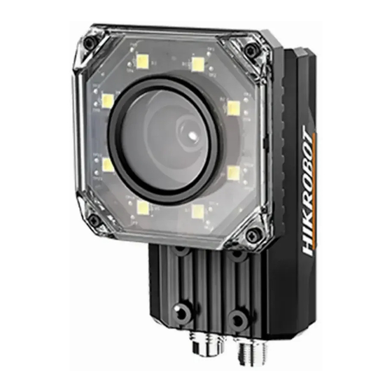
Page 9: Chapter 1 Appearance
ID5000 Series Smart Code Reader Chapter 1 Appearance Figure 1-1 Appearance Table 1-1 Description Name Description It can be replaced with other lens cap. Polarization lens cap is Lens Cap optional. It is used to fix the device to installation position. It is Screw Hole recommended to use M4 screw. - Page 10 ID5000 Series Smart Code Reader Name Description It is the power indicator. The indicator is solid blue when the device PWR Indicator operates normally. It is network connection indicator. The indicator is solid green LNK Indicator when the network transmission is normal.
-
Page 11: Chapter 2 Interface And Indicator
ID5000 Series Smart Code Reader Chapter 2 Interface and Indicator 2.1 12-Pin Interface Read the following section to get definitions of 12-pin interface. Figure 2-1 12-Pin Interface Table 2-1 Pin Definitions Signal I/O Signal Source Description DC-PWR Direct current power supply positive... - Page 12 ID5000 Series Smart Code Reader Note You should refer to the table above and the label attached to the power and I/O cable to wire the device. The device supports RS-232 serial port output, and you can set serial port parameters in client software.
-
Page 13: Indicator Status
ID5000 Series Smart Code Reader The RS-232 serial port wiring is shown below. Device Power RS-232 Serial Port External Output Device RS-232 Serial Port Input Device Power Ground Figure 2-4 RS-232 Serial Port Wiring 2.2 Indicator Status Read the following section to get the indicator status of the device. -
Page 14: Chapter 3 I/O Wiring
ID5000 Series Smart Code Reader Chapter 3 I/O Wiring 3.1 Input Signal The device's LineIn 0/1/2 is opto-isolated input, and their internal circuit is as follows. Note ● The input voltage ranges from 5 VDC to 30 VDC. ● The maximum current is 5 mA. -
Page 15: Input Signal Wiring
ID5000 Series Smart Code Reader 3.3 Input Signal Wiring The device can receive external input signal via I/O interface, and here we take LineIn 0 as an example to introduce input signal wiring. Note Input signal wiring may differ with different types of external devices. -
Page 16: Output Signal Wiring
ID5000 Series Smart Code Reader NPN Device Power Device Power Opto-Isolated Signal Line Input Device Input Signal Ground NPN Power Ground Device Power Ground GND of VCC GND of PWR Figure 3-5 Input Signal Connecting to NPN Device with Pull-Up Resistor 3.4 Output Signal Wiring... - Page 17 ID5000 Series Smart Code Reader Device Power Output Signal NPN Device Power Ground Device Opto-Isolated Output Signal Line Device Power Ground NPN Power Ground GND of PWR GND of VCC Figure 3-7 Output Signal Connecting to NPN Device without Pull-Up Resistor If the VCC of NPN device is 12 VDC or 24 VDC and 1 KΩ...
-
Page 18: Chapter 4 Installation
ID5000 Series Smart Code Reader Chapter 4 Installation 4.1 Installation Preparation You need to prepare following accessories before installation. Table 4-1 Accessories Name Quantity Description Power and I/O Cable It refers to the 12-pin power and I/O cable. It refers to the GigE network cable with RJ45 Network Cable aviation connector. - Page 19 ID5000 Series Smart Code Reader Figure 4-1 Rear Installation Figure 4-2 Front Installation 3. Use GigE network cable with RJ45 aviation connector to connect the device to a switch or a network interface card.
-
Page 20: Install Client Software
ID5000 Series Smart Code Reader Figure 4-3 Gigabit Ethernet Interface Wiring 4. Use power and I/O cable to connect the device to a DC switch power supply. Figure 4-4 Power and I/O Wiring 4.3 Install Client Software IDMVS is a client software for camera configuration and remote operations. -
Page 21: Turn Off Firewall
ID5000 Series Smart Code Reader 1. Double click the installation package to start installing the client software. 2. Select the language. 3. Read and check Terms of the License Agreement. 4. Click Start Setup. 5. Select installation directory and click Next. - Page 22 ID5000 Series Smart Code Reader Figure 4-6 Windows Defender Firewall 4. Click OK.
-
Page 23: Chapter 5 Network Settings
ID5000 Series Smart Code Reader Chapter 5 Network Settings 5.1 Set PC Network To ensure stable image transmission and normal communication between the PC and the camera via client software, you need to set the PC network before using the client software. -
Page 24: Set Device Network
ID5000 Series Smart Code Reader 1) Go to NIC settings page: Control Panel → Hardware and Sound → Device Manager → Network Adapter. 2) Select corresponding network interface card, and click Advanced. 3) Set Jumbo Packet value to 9014 Bytes, Transmit Buffers and Receive Buffers to 2048, Interrupt Moderation Rate to Extremum. -
Page 25: Chapter 6 Client Software Layout
ID5000 Series Smart Code Reader Chapter 6 Client Software Layout After connecting to the device, the client software can read the device information and display it. Figure 6-1 Main Window Table 6-1 Description of the Main Window Name Description The menu bar displays function modules, including Menu Bar Settings, Tool, View, and Help. - Page 26 ID5000 Series Smart Code Reader Figure 6-2 Device Configuration Area Table 6-2 Description Module Name Description You can connect or disconnect device, modify device IP Device Connection address, view device information, etc. Image Settings You can set image parameters, light parameters, etc.
- Page 27 ID5000 Series Smart Code Reader Note You should stop real-time acquisition before selecting camera modes. Figure 6-3 Select Camera Modes You can click in live view window to view image and code reading effect. Note If code reading effect is not very good, you can adjust related parameters in Image Settings or adjust focus knob on the device.
- Page 28 ID5000 Series Smart Code Reader Figure 6-5 History...
-
Page 29: Chapter 7 Camera Settings
ID5000 Series Smart Code Reader Chapter 7 Camera Settings You are recommended to complete camera settings in following order: Device Connection → Image Settings → Algorithm Settings → I/O Control Settings → Data Processing → Communication Settings → Configuration Management. -
Page 30: Image Quality Settings
ID5000 Series Smart Code Reader Figure 7-1 Select Camera Modes Table 7-1 Description Camera Mode Description It is used during camera debugging. The camera outputs images that are Test Mode acquired in real-time, and displays barcode information. It is used during camera normal operation. After reading barcode in Normal Mode image, the camera outputs image and barcode information. - Page 31 ID5000 Series Smart Code Reader acquisition burst frame count in image parameters interface. Note ● Make sure you have select the camera to be set in Device Connection before setting image parameters. ● For specific parameter range like exposure time, gain and acquisition frame rate, refer to the camera's specification for details.
-
Page 32: Set Light Source
ID5000 Series Smart Code Reader Figure 7-2 Set Image 7.3.2 Set Light Source You can select different light types, and set their related parameters in light interface. Note ● For different models of camera, the light source parameters may be different, and the actual product you purchased shall prevail. -
Page 33: Barcode Algorithm Settings
ID5000 Series Smart Code Reader Note This parameter is available only when you set Flash Strobe as the Light Mode. Figure 7-3 Own Lighting If you select External Lighting as Light Type, you can set the following parameters. Line Out Duration The lighting duration of the external light source and the unit is μs. - Page 34 ID5000 Series Smart Code Reader out in Algorithm Settings. Note ● Do not select excessive amount of barcode types. The more types you select, the more time will be consumed to recognize the codes in the image. ● Do not set excessive value in 1D Code Number and 2D Code Number. The more you set, the more time will be consumed to recognize the codes in the image.
-
Page 35: Set 1D Algorithm Parameter
ID5000 Series Smart Code Reader Figure 7-6 1D Code Number and 2D Code Number 7.4.2 Set 1D Algorithm Parameter You can set the parameters related to algorithm for the 1D code. Note You should have selected at least one type of 1D code. -
Page 36: Set 2D Algorithm Parameter
ID5000 Series Smart Code Reader If the barcode printing quality is not good, you can enable this parameter to improve barcode recognition rate. Note If you enable this parameter, the more time will be consumed to recognize the codes in the image. - Page 37 ID5000 Series Smart Code Reader Click All Features on the upper-right to display all algorithm parameters, and select 2DCode as Arithmetic Type. Waiting Time It sets the maximum running time of algorithm, and the device will stop parsing the images and return result if the time is exceeded, and the unit is ms.
- Page 38 ID5000 Series Smart Code Reader Figure 7-9 Black QR Code ● For DM code, the code color is determined by the color of its "L" shaped sides. White "L" shaped sides indicate that the code color is white, and black "L" shaped sides indicate that the code color is black.
-
Page 39: Signal Input Settings
ID5000 Series Smart Code Reader If the QR code or DM code is distorted, you can enable this parameter to improve code recognition rate. Note If you enable this parameter, the more time will be consumed to recognize the codes in the image. -
Page 40: Set Trigger Mode
ID5000 Series Smart Code Reader mode to let the acquisition of image data occur only when the trigger source is generated. 7.5.1 Set Trigger Mode The camera has 2 types of trigger modes, including internal trigger mode and external trigger mode. - Page 41 ID5000 Series Smart Code Reader You can also enter Auto Trigger Time, and then enable Enable Auto Trigger to let the client software automatically send trigger signal to camera according to the interval you set. Figure 7-13 Set and Execute Software Trigger Mode...
- Page 42 ID5000 Series Smart Code Reader 2. Select On as Trigger Mode. 3. Select Counter 0 as Trigger Source. 4. Set Trigger Delay, Count Number, and Count Source according to actual demands. Figure 7-15 Set and Execute Counter Trigger Mode Set and Execute TCP Trigger Mode TCP start specifies the TCP server as the source for the trigger signal.
- Page 43 ID5000 Series Smart Code Reader Set Trigger Delay, Udp Trigger Port, and Udp Start Trigger Text according to actual demands. Figure 7-17 Set and Execute UDP Trigger Mode Set and Execute Serial Port Trigger Mode Serial start specifies the serial port as the source for the trigger signal. When the serial port receives the specified string text, the trigger signal will be outputted.
-
Page 44: Stop Trigger
ID5000 Series Smart Code Reader 7.5.4 Stop Trigger Stop trigger settings configure the source and condition to stop trigger. You can stop device trigger via TCP, UDP, I/O and serial port. TCP Stop Trigger When the TCP server receives the specified string text, the trigger will be stopped. - Page 45 ID5000 Series Smart Code Reader Figure 7-21 IO Stop Trigger When selecting SoftwareTriggerEnd as IO Stop Trigger Selector, you can click Execute in Software Stop Trigger to stop current trigger. Figure 7-22 SoftwareTriggerEnd Serial Stop Trigger When the specified serial port receives the specified string text, the trigger will be stopped.
-
Page 46: Signal Output Settings
ID5000 Series Smart Code Reader Figure 7-23 Serial Stop Trigger 7.6 Signal Output Settings 7.6.1 Select Output Signal The device has 3 outline lines (LineOut 0, LineOut 1, LineOut 2) that can be used as output signal. Click I/O Control Settings → Output → Line Out Selector to select output signal. -
Page 47: Enable Line Inverter
ID5000 Series Smart Code Reader 7.6.2 Enable Line Inverter The level inverter function allows the camera to invert the electrical signal level of an I/O line, and meets requirements of different devices for high or low electrical signal level. You can go to I/O Control Settings → Output → Line Out Inverterto enable it. - Page 48 ID5000 Series Smart Code Reader If the burst of a frame stops, the output signal will be triggered. ExposureStartActive If the exposure starts, the output signal will be triggered. SoftTriggerActive The client software triggers the output signal. HardTriggerActive The external signals trigger the output signal.
- Page 49 ID5000 Series Smart Code Reader Figure 7-26 Set Event Source Select Acquisition Start Active If you select AcquisitionStartActive as Line Out Activation Event, you can set its output delay time and duration. Line Out Delay Time It sets the delay time for outputting the output signal.
- Page 50 ID5000 Series Smart Code Reader Figure 7-27 Select Acquisition Start Active Select Acquisition Stop Active If you select AcquisitionStopActive as Line Out Activation Event, you can set its output delay time and duration. Line Out Delay Time It sets the delay time for outputting the output signal.
- Page 51 ID5000 Series Smart Code Reader It sets the time duration of the output signal. Figure 7-29 Select Frame Burst Start Active Select Frame Burst End Active If you select Frame Burst End Active as Line Out Activation Event, you can set its output delay time and duration.
- Page 52 ID5000 Series Smart Code Reader It sets the delay time for outputting the output signal. Line Out Duration It sets the time duration of the output signal. Figure 7-31 Select ExposureStartActive Select Soft Trigger Active If you select Soft Trigger Active as Line Out Activation Event, you can set its output delay time, duration, and execute outputting signal manually.
- Page 53 ID5000 Series Smart Code Reader Select Hard Trigger Active If you select Hard Trigger Active as Line Out Activation Event, you can set its output delay time, duration, trigger source, and trigger activation. Line Out Delay Time It sets the delay time for outputting the output signal.
-
Page 54: Code Reading Settings
ID5000 Series Smart Code Reader Figure 7-34 Select NoCodeRead Select ReadSuccess If you select ReadSuccess as Line Out Activation Event, you can set its output delay time and duration. Line Out Delay Time It sets the delay time for outputting the output signal. -
Page 55: Set Filter Rule
ID5000 Series Smart Code Reader related parameters. 7.7.1 Set Filter Rule You can set rules to filter unwanted barcodes to improve the reading efficiency in Filter Rule. When the camera mode is Normal and Trigger Mode is On, you can set the following parameters according to actual demands. -
Page 56: Set Data Processing
ID5000 Series Smart Code Reader Exclude Specific Character in Barcode If this parameter is enabled, the device will only read the barcodes which exclude a specific character. Otherwise, the barcodes will be filtered out. You can enter the specific character in Character. - Page 57 ID5000 Series Smart Code Reader ● With different communication protocols, you need to set corresponding parameters for data processing. SmartSDK Data Processing When the communication protocol is SmartSDK, you need to set following parameter in the Data Processing. NoRead Image Index It sets the specific image that is outputted when no barcode information is read.
- Page 58 ID5000 Series Smart Code Reader When no barcode is recognized, the device will output the content you set here. Note The default content is NoRead. Tcp Output Start Text The contents of the start part of the data outputted. You can set the contents according to actual condition.
- Page 59 ID5000 Series Smart Code Reader If this parameter is enabled, the outputted barcode information will contain the position of the barcode. Serial Output Barcode Angle Enable If this parameter is enabled, the outputted barcode information will contain the angle of the barcode.
- Page 60 ID5000 Series Smart Code Reader FTP Data Processing When the communication protocol is FTP, you need to set following parameters in the Data Processing. NoRead Image Index It sets the specific image that is outputted when no barcode information is read. For example, if you set this parameter as 5, and the 5th image will be output.
- Page 61 ID5000 Series Smart Code Reader Ftp File Name Contain Barcode Number Enable If this parameter is enabled, the name of the file uploaded to FTP server will contain the number of the barcode. Ftp File Name Contain FtpTimeStamp Type It selects a format type from the drop-down list for the time stamp contained in the file name.
- Page 62 ID5000 Series Smart Code Reader Data Processing. NoRead Image Index It sets the specific image that is outputted when no barcode information is read. For example, if you set this parameter as 5, and the 5th image will be output.
-
Page 63: Communication Settings
ID5000 Series Smart Code Reader Figure 7-42 TCP Server Data Processing 7.8 Communication Settings The communication settings determine how the device outputs the barcode data. You can go to Communication Settings module to select different communication protocols, and set corresponding parameters. -
Page 64: Tcp Client
ID5000 Series Smart Code Reader Figure 7-43 Smart SDK 7.8.2 TCP Client The TCP includes TCP Server and TCP Client. If selectTCP Client as the Communication Protocols, you need to set following parameters. Output Result Buffer If enabled, when the TCP server is abnormal, the device will cache the images. When the server returns to normal, the device will send the cached images to the server. -
Page 65: Serial
ID5000 Series Smart Code Reader Figure 7-45 TCP Server 7.8.4 Serial If select Serial as the Communication Protocols, you can enable Serial Protocol, enter SerialBaudrate, Serial Data Bits, Serial parity, and Serial Stop Bits. Figure 7-46 Serial 7.8.5 FTP If select FTP as the Communication Protocols, you need to set following parameters. -
Page 66: Http
ID5000 Series Smart Code Reader Figure 7-47 FTP 7.8.6 HTTP If select HTTP as the Communication Protocols, you can enable HTTP Server, enter HTTP Sever Port and WebRefresh Cycle. HTTP Server If enabled, the device will output data via HTTP server. -
Page 67: User Set Customization
ID5000 Series Smart Code Reader Figure 7-48 HTTP 7.9 User Set Customization The Configuration Management module allows you to set and manage the user set. A user set is a group of parameter values with all the settings needed to control the device, and you can save, load and switch different user sets. - Page 68 ID5000 Series Smart Code Reader Figure 7-49 User Set Customization...
-
Page 69: Chapter 8 Camera Operation
ID5000 Series Smart Code Reader Chapter 8 Camera Operation The camera operation section introduces some basic camera operations about how to start live view, acquisition and recording, add cross line in the image, split window, view reports, etc. Note Connecting the device to the client software is required before camera operation. -
Page 70: Add Cross Line
ID5000 Series Smart Code Reader Figure 8-2 Enable Acquisition 8.3 Add Cross Line During live view, you can add a cross line on the live view image to adjust the position of the object in the view. Click in live view window to add cross line, and click... -
Page 71: Split Window
ID5000 Series Smart Code Reader Figure 8-4 Start Recording 8.5 Split Window The client software supports window division function that allows you to split the window into multiple-window mode to view the live view of multiple devices at the same time. -
Page 72: View Log
ID5000 Series Smart Code Reader 8.7 View Log You can view the device logs and export the them to the local PC. Click in control toolbar to open the device log window, and you can view different types of logs, including device errors, warning, and informational log, etc. -
Page 73: Chapter 9 Camera Maintenance
ID5000 Series Smart Code Reader Chapter 9 Camera Maintenance 9.1 Update Firmware The device supports updating firmware via the client software. Note ● Disconnect the device with client software. ● Please use the firmware package of the corresponding device model for upgrading. -
Page 74: Chapter 10 Faq (Frequently Asked Question)
ID5000 Series Smart Code Reader Chapter 10 FAQ (Frequently Asked Question) 10.1 Why the image is very dark? Problem All black or too dark during preview. Reason ● Insufficient brightness of supplement light. ● Too small adjustment value of exposure and gain. -
Page 75: Why There Is No Image In The Live View
ID5000 Series Smart Code Reader Solution ● Check the device power connection (observe whether the top PWR light is solid green or not), to make sure the device is powered up normally. ● Check the network connection (observe whether the top LNK light is flashing green or not), to make sure the device can be connected to the network normally. -
Page 76: Chapter 11 Revision History
ID5000 Series Smart Code Reader Chapter 11 Revision History Table 11-1 Revision History Version No. Document No. Date Revision Details 1.0.0 UD17611B Dec. 20, 2019 Original version. - Page 77 UD17611B...
Need help?
Do you have a question about the ID5000 Series and is the answer not in the manual?
Questions and answers