Table of Contents
Advertisement
Quick Links
Advertisement
Table of Contents

Related Manuals for HikRobot ID6000 Series


Summary of Contents for HikRobot ID6000 Series
- Page 1 ID6000 Series Smart Code Reader User Manual...
- Page 2 INTERRUPTION, OR LOSS OF DATA, CORRUPTION OF SYSTEMS, OR LOSS OF DOCUMENTATION, WHETHER BASED ON BREACH OF CONTRACT, TORT (INCLUDING NEGLIGENCE), PRODUCT LIABILITY, OR OTHERWISE, IN CONNECTION WITH THE USE OF THE PRODUCT, EVEN IF HIKROBOT HAS BEEN ADVISED OF THE POSSIBILITY OF SUCH DAMAGES OR LOSS.
- Page 3 ID6000 Series Smart Code Reader User Manual RIGHTS ABUSES. THE PERFORMANCE DATA IN THIS PUBLICATION IS BASED ON HIKROBOT'S INTERNAL RESEARCH/EVALUATION. ACTUAL DATA MAY VARY DEPENDING ON SPECIFIC CONFIGURATIONS AND OPERATING CONDITIONS AND HIKROBOT SHALL NOT BEAR THE CONSEQUENCES ARISING THEREFROM.
- Page 4 Note important points of the main text. Available Model This manual is applicable to the ID6000 Series Smart Code Reader. Safety Instruction These instructions are intended to ensure that the user can use the product correctly to avoid danger or property loss.
- Page 5 ID6000 Series Smart Code Reader User Manual Power Supply ● When wiring or dismounting, make sure that the device power is cut off, and do not operate under electrification. ● Avoid contact with exposed circuit. When the device is powered on, avoid contact with exposed junctions and parts.
- Page 6 ID6000 Series Smart Code Reader User Manual ● Put electrostatic sensitive components into anti-static bags for protection. ● It is suggested to place humidifier in dry environment to maintain suitable humidity and reduce static electricity generation. Maintenance ● If the product is not working properly, contact the store or the nearest service center. Do not disassemble or modify the device in any way.
-
Page 7: Table Of Contents
ID6000 Series Smart Code Reader User Manual Contents Chapter 1 Appearance ........................1 Chapter 2 Interface and Indicator ....................3 2.1 12-Pin Interface......................... 3 2.2 Indicator Status ......................... 4 Chapter 3 I/O Wiring ........................5 3.1 Input Signal ........................5 3.2 Output Signal ........................ - Page 8 ID6000 Series Smart Code Reader User Manual 7.4.2 Set 1D Algorithm Parameter ................26 7.4.3 Set 2D Algorithm Parameter ................27 7.5 Signal Input Settings ....................... 30 7.5.1 Set Trigger Mode ....................30 7.5.2 Enable Internal Trigger Mode ................31 7.5.3 Enable External Trigger Mode ................
- Page 9 ID6000 Series Smart Code Reader User Manual 8.6 View Reports........................65 8.7 View Log ......................... 66 8.8 Enable Camera Auto Work ....................66 Chapter 9 Camera Maintenance ....................67 9.1 Update Firmware ......................67 9.2 Reboot Device ......................... 67 Chapter 10 FAQ (Frequently Asked Question) ................69 10.1 Why there is no camera listed after I run the IDMVS client software? ......
-
Page 10: Chapter 1 Appearance
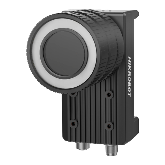
ID6000 Series Smart Code Reader User Manual Chapter 1 Appearance Note Appearance here is for reference only. Refer to the device's specification for detailed dimension information. Figure 1-1 Appearance (Type I) Figure 1-2 Appearance (Type II) - Page 11 ID6000 Series Smart Code Reader User Manual Table 1-1 Description Name Description It refers to the device’s lens cap. Lens Cap Note The type II device does not have the lens cap. It is used to fix the device to installation position. It is Screw Hole recommended to use M4 screw.
-
Page 12: Chapter 2 Interface And Indicator
ID6000 Series Smart Code Reader User Manual Chapter 2 Interface and Indicator 2.1 12-Pin Interface Read the following section to get definitions of 12-pin interface. Figure 2-1 12-Pin Interface Table 2-1 Pin Definitions Signal I/O Signal Source Description Direct current power supply... -
Page 13: Indicator Status
ID6000 Series Smart Code Reader User Manual Note You should refer to the table above and the label attached to the power and I/O cable to wire the device. 2.2 Indicator Status The device is equipped with one PWR indicator, one LNK indicator, one ACT indicator, and 2 custom indicators (U1 and U2). -
Page 14: Chapter 3 I/O Wiring
ID6000 Series Smart Code Reader User Manual Chapter 3 I/O Wiring 3.1 Input Signal The device's LineIn 0/1/2 is opto-isolated input, and their internal circuit is as follows. Note ● The input voltage ranges from 5 VDC to 30 VDC. -
Page 15: Input Signal Wiring
ID6000 Series Smart Code Reader User Manual 3.3 Input Signal Wiring The device can receive external input signal via I/O interface, and here we take LineIn 0 as an example to introduce input signal wiring. Note Input signal wiring may differ with different types of external devices. -
Page 16: Output Signal Wiring
ID6000 Series Smart Code Reader User Manual 3.4 Output Signal Wiring The device can output signal to external device via I/O interface, and here we take LineOut 0 as an example to introduce output signal wiring. Note ● Output signal wiring may differ with different types of external devices. -
Page 17: Rs-232 Serial Port
ID6000 Series Smart Code Reader User Manual Figure 3-8 Output Signal Connecting to NPN Device with Pull-Up Resistor 3.5 RS-232 Serial Port The 9-pin male connector and 25-pin male connector are commonly used serial ports, as shown below. You can refer to the table below for the specific pin name and function. - Page 18 ID6000 Series Smart Code Reader User Manual You can refer to the serial port wiring below to connect the smart code reader with an external device. Device Power RS-232 Serial Port External Output Device RS-232 Serial Port Input Device Power...
-
Page 19: Chapter 4 Installation
ID6000 Series Smart Code Reader User Manual Chapter 4 Installation 4.1 Installation Preparation You need to prepare following accessories before installation. Table 4-1 Accessories Name Quantity Description Power and I/O It refers to the 12-pin power and I/O cable. You Cable need to purchase separately. - Page 20 ID6000 Series Smart Code Reader User Manual Figure 4-1 Rear Installation Figure 4-2 Front Installation...
- Page 21 ID6000 Series Smart Code Reader User Manual Figure 4-3 Side Installation 2. Use GigE network cable with RJ45 aviation connector to connect the device to a switch or a network interface card. Figure 4-4 Gigabit Ethernet Interface Wiring 3. Use power and I/O cable to connect the device to a DC switch power supply.
-
Page 22: Install Client Software
ID6000 Series Smart Code Reader User Manual 4.3 Install Client Software IDMVS is a client software for camera configuration and remote operations. Steps Note ● Check the Windows version. The client software is compatible with 32/64-bit Windows XP/7/10. ● You can mail to tech_support@hikrobotics.com to get client software installation package. - Page 23 ID6000 Series Smart Code Reader User Manual Windows firewall before using the client software. Steps Note For different Windows versions, the path name or interface may differ. Please refer to the actual condition. 1. Go to Windows Firewall. Windows XP system: Click Start → Control Panel → Security Center → Windows Firewall.
-
Page 24: Chapter 5 Network Settings
ID6000 Series Smart Code Reader User Manual Chapter 5 Network Settings 5.1 Set PC Network To ensure stable image transmission and normal communication between the PC and the camera via client software, you need to set the PC network before using the client software. -
Page 25: Set Device Network
ID6000 Series Smart Code Reader User Manual 1) Go to NIC settings page: Control Panel → Hardware and Sound → Device Manager → Network Adapter. 2) Select corresponding network interface card, and click Advanced. 3) Set Jumbo Packet value to 9014 Bytes, Transmit Buffers and Receive Buffers to 2048, Interrupt Moderation Rate to Extremum. - Page 26 ID6000 Series Smart Code Reader User Manual Figure 5-3 Modify IP Address 6. Click OK.
-
Page 27: Chapter 6 Client Software Layout
ID6000 Series Smart Code Reader User Manual Chapter 6 Client Software Layout After connecting to the device, the client software can read the device information and display it. Figure 6-1 Main Window Note The specific interfaces of the client software may differ by its versions. - Page 28 ID6000 Series Smart Code Reader User Manual You can set device parameters in device configuration area. Figure 6-2 Device Configuration Area Table 6-2 Description Module Name Description You can connect or disconnect device, modify device IP Device Connection address, view device information, etc.
- Page 29 ID6000 Series Smart Code Reader User Manual Note You should stop real-time acquisition before selecting camera modes. Figure 6-3 Select Camera Modes You can click in live view window to view image and code reading effect. Note If code reading effect is not very good, you can adjust related parameters in Image Settings.
-
Page 30: Chapter 7 Camera Settings
ID6000 Series Smart Code Reader User Manual Chapter 7 Camera Settings You are recommended to complete camera settings in following order: Device Connection → Image Settings → Algorithm Settings → I/O Control Settings → Data Processing → Communication Settings → Configuration Management. -
Page 31: Image Quality Settings
ID6000 Series Smart Code Reader User Manual Figure 7-1 Select Camera Modes Table 7-1 Description Camera Mode Description It is used during camera debugging. The camera outputs images that are Test Mode acquired in real-time, and displays barcode information. It is used during camera normal operation. After reading barcode in image, Normal Mode the camera outputs image and barcode information. - Page 32 ID6000 Series Smart Code Reader User Manual ● For specific parameter range like exposure time, gain and acquisition frame rate, refer to the camera's specification for details. Exposure Time You can increase exposure time to improve image brightness. Note To some extent, increasing exposure time will reduce acquisition frame rate, and impact image quality.
-
Page 33: Set Light Source
ID6000 Series Smart Code Reader User Manual 7.3.2 Set Light Source You can select different light types, and set their related parameters in corresponding interface. Note ● Light source parameters may differ by camera model. ● Make sure you have select the camera to be set in Device Connection before setting light parameters. -
Page 34: Set Test Pattern
ID6000 Series Smart Code Reader User Manual Note This function is enabled by default, and it may differ by device models. 7.3.4 Set Test Pattern Test pattern refers to the device's test images. When exceptions occur in images acquired by the device in real time, you can check if images under the test pattern have similar problems to determine the cause of an exception. -
Page 35: Set 1D Algorithm Parameter
ID6000 Series Smart Code Reader User Manual Figure 7-4 1D Code and 2D Code 7.4.2 Set 1D Algorithm Parameter Click All Features on the upper-right to display all algorithm parameters. In the Algorithm Parameter page, select 1DCode as Arithmetic Type, and then you can set its corresponding parameters, like the maximum running time of algorithm, distortion, etc. -
Page 36: Set 2D Algorithm Parameter
ID6000 Series Smart Code Reader User Manual Figure 7-5 Set 1D Algorithm Parameter 7.4.3 Set 2D Algorithm Parameter Click All Features on the upper-right to display all algorithm parameters. In the Algorithm Parameter page, select 2D Code as Arithmetic Type, and then you can set its corresponding parameters, like the maximum running time of algorithm, algorithm operating mode, etc. - Page 37 ID6000 Series Smart Code Reader User Manual Note Increasing this parameter value will improve the code reading efficiency at the cost of code recognition rate. Code Color It defines the readable code color. Adaptive means that the client software can recognize both the black code with white background, and the white code with black background.
- Page 38 ID6000 Series Smart Code Reader User Manual Figure 7-8 White DM Code Figure 7-9 Black DM Code Discrete Flag Continuous stands for the minimum units in the "L" shaped sides of the DM code are continuous, or the minimum units in the concentric square like in the QR code are continuous.
-
Page 39: Signal Input Settings
ID6000 Series Smart Code Reader User Manual The device can recognize 2D codes of both the above-mentioned two shapes. Figure 7-10 Set 2D Algorithm Parameter 7.5 Signal Input Settings In the signal input module, you can set the trigger related parameters. You can enable trigger mode to let the acquisition of image data occur only when the trigger source is generated. -
Page 40: Enable Internal Trigger Mode
ID6000 Series Smart Code Reader User Manual 7.5.2 Enable Internal Trigger Mode You can click I/O Control Settings → Input → Trigger Mode, and select Off as Trigger Mode. In this mode, the camera acquires images via its internal signals, and you do not need to set any parameters. - Page 41 ID6000 Series Smart Code Reader User Manual Set and Execute Hardware Trigger Mode Steps 1. Click I/O Control Settings → Input → Trigger Mode. 2. Select On as Trigger Mode. 3. Select LineIn 0, LineIn 1 or LineIn 2 as Trigger Source.
- Page 42 ID6000 Series Smart Code Reader User Manual Figure 7-13 Set and Execute Counter Trigger Mode Set and Execute TCP Trigger Mode TCP start specifies the TCP server as the source for the trigger signal. When the server receives the specified string text, the trigger signal will be outputted.
-
Page 43: Stop Trigger
ID6000 Series Smart Code Reader User Manual Figure 7-15 Set and Execute UDP Trigger Mode Set and Execute Serial Port Trigger Mode Serial start specifies the serial port as the source for the trigger signal. When the serial port receives the specified string text, the trigger signal will be outputted. - Page 44 ID6000 Series Smart Code Reader User Manual reading timeout duration or max. barcode amount to be read to stop trigger. After stopping trigger is completed, the device cannot make response to trigger again. Stop Trigger via IO You can stop a trigger via IO: Enabling IO Stop Trigger Enable first, select specific sources from IO Stop Trigger Selector, and then set the trigger polarity as the condition to stop trigger.
- Page 45 ID6000 Series Smart Code Reader User Manual 38400, 57600 and 115200, and Serial Data Bits is 8. Figure 7-19 Stop Trigger via Serial Stop Trigger via UDP When the UDP server receives the specified string text, the trigger will be stopped. The client software sends stop trigger command to the device after Udp Stop Trigger Enable is enabled.
- Page 46 ID6000 Series Smart Code Reader User Manual Stop Trigger via TCP When the TCP server receives the specified string text, the trigger will be stopped. The client software sends stop trigger command to the device after Tcp Stop Trigger Enable is enabled. You should enter Tcp Trigger Port and Tcp Stop Trigger Text according to actual demands.
-
Page 47: Signal Output Settings
ID6000 Series Smart Code Reader User Manual Figure 7-23 Stop Trigger via Max. Code Number 7.6 Signal Output Settings 7.6.1 Select Output Signal The device has 3 outline lines (LineOut 0, LineOut 1, LineOut 2) that can be used as output signal. -
Page 48: Set Event Source
ID6000 Series Smart Code Reader User Manual Figure 7-25 Enable Line Out Inverter 7.6.3 Set Event Source Note For different models of camera, the event source parameters may be different, and the actual product you purchased shall prevail. The device supports outputting different trigger signals according to the event source you select. - Page 49 ID6000 Series Smart Code Reader User Manual Figure 7-26 Set Event Source Select Acquisition Start Active If acquisition starts, the output signal will be triggered. When you select AcquisitionStartActive as Line Out Activation Event, you can set its output delay time and duration.
- Page 50 ID6000 Series Smart Code Reader User Manual Select Acquisition Stop Active If acquisition stops, the output signal will be triggered. When you select AcquisitionStopActive as Line Out Activation Event, you can set its output delay time and duration. Line Out Delay Time It sets the delay time for outputting the output signal.
- Page 51 ID6000 Series Smart Code Reader User Manual Figure 7-29 Select Frame Burst Start Active Select Frame Burst Stop Active Note The Frame Burst Stop Active is not supported when the trigger polarity is level high or level low. If the burst of a frame stops, the output signal will be triggered. When you select Frame Burst Stop Active as Line Out Activation Event, you can set its output delay time and duration.
- Page 52 ID6000 Series Smart Code Reader User Manual Select Exposure Start Active Note For different models of camera, when selecting ExposureStartActive as Line Out Activation Event, the specific parameters may be different. The actual product you purchased shall prevail. If you select ExposureStartActive as Line Out Activation Event, you can set its output delay time and duration.
- Page 53 ID6000 Series Smart Code Reader User Manual Figure 7-32 Select Soft Trigger Active Select Hard Trigger Active If you select Hard Trigger Active as Line Out Activation Event, you can set its output delay time, duration, trigger source, and trigger activation.
- Page 54 ID6000 Series Smart Code Reader User Manual Select Counter Active Counter active means that the counter triggers the output signal. When you select Counter Active as Line Out Activation Event, you can set its output delay time and duration. Line Out Delay Time It sets the delay time for outputting the output signal.
- Page 55 ID6000 Series Smart Code Reader User Manual Figure 7-35 Select Timer Active Select No Code Read If you select NoCodeRead as Line Out Activation Event, you can set its output delay time and duration. Line Out Delay Time It sets the delay time for outputting the output signal.
-
Page 56: Code Reading Result Settings
ID6000 Series Smart Code Reader User Manual Figure 7-37 Select Read Success Select Light Strobe Long If you select LightStrobeLong as Line Out Activation Event, you do not need to set any parameters. Select Light Continued If you select LightContinued as Line Out Activation Event, you do not need to set any parameters. -
Page 57: Set Filter Rule
ID6000 Series Smart Code Reader User Manual 7.7.2 Set Filter Rule You can set rules to filter unwanted barcodes to improve the reading efficiency in Filter Rule. Note The filter rule parameters may differ with different camera modes and trigger modes. -
Page 58: Set Result Format
ID6000 Series Smart Code Reader User Manual If this parameter is enabled, the device will only read the barcodes which include a specific character. Otherwise, the barcodes will be filtered out. You can enter the specific character in Character. Exclude Specific Character in Barcode If this parameter is enabled, the device will only read the barcodes which exclude a specific character. - Page 59 ID6000 Series Smart Code Reader User Manual parameters. Note ● Result format settings are only available if you select TCP Client, TCP Server, Serial or FTP as the communication protocol when the camera mode is Normal. Result format settings are not available for Smart SDK and HTTP.
- Page 60 ID6000 Series Smart Code Reader User Manual Tcp Output Barcode Angle Enable If this parameter is enabled, the outputted barcode information will contain the angle of the barcode. Tcp Output Barcode MainPackageID Enable If this parameter is enabled, the outputted barcode information will contain the package ID.
- Page 61 ID6000 Series Smart Code Reader User Manual Result Output via TCP Server When the communication protocol is TCP Server, camera mode is Normal and trigger mode is On, you need to set following parameters in the Data Processing. NoRead Image Index It sets the specific image that is outputted when no barcode information is read.
- Page 62 ID6000 Series Smart Code Reader User Manual Figure 7-41 Result Output via TCP Server When the communication protocol is TCP Server, camera mode is Normal and trigger mode is Off, you can set TcpServer Output Barcode Name Enable, TcpServer Output Barcode Position Enable, TcpServer Output Barcode Angle Enable, TcpServer Output Barcode MainPackageID Enable, TcpServer Output Start Text,TcpServer Output Stop Text, and TcpServer Output TcpDelimiter.
- Page 63 ID6000 Series Smart Code Reader User Manual Serial Output Start Text The contents of the start part of the data outputted. You can set the contents according to actual condition. Serial Output Stop Text The contents of the end part of the data outputted. You can set the contents according to actual condition.
- Page 64 ID6000 Series Smart Code Reader User Manual Figure 7-43 Result Output via Smart HTTP Result Output via FTP When the communication protocol is FTP, camera mode is Normal and trigger mode is On, you need to set following parameters in the Data Processing.
-
Page 65: Set Cutout
ID6000 Series Smart Code Reader User Manual condition. Ftp File Separator It refers to the separator that separates file name. You can set it according to actual condition. Ftp File Name Contain Package Number Enable If this parameter is enabled, the name of the file uploaded to FTP server will contain the package ID. -
Page 66: Communication Settings
ID6000 Series Smart Code Reader User Manual Right click the device, click Feature Tree to display the feature tree, and enable Bill Info Enable in Communication Control. Go to Algorithm Settings →Waybill Cutout, and enable Waybill Cutout Enable first. Select the format of the cutted-out image in Cutted-out Image Format, and set the quality of the cutted-out image if you select JPG as its format. -
Page 67: Tcp Client
ID6000 Series Smart Code Reader User Manual Figure 7-46 Smart SDK 7.8.2 TCP Client The TCP includes TCP Server and TCP Client. If select TCP Client as the Communication Protocols, you need to set following parameters. Output Result Buffer If enabled, when the TCP server is abnormal, the device will cache the images. When the server returns to normal, the device will send the cached images to the server. -
Page 68: Serial
ID6000 Series Smart Code Reader User Manual Figure 7-48 TCP Server 7.8.4 Serial If select Serial as the Communication Protocols, you can enable Serial Protocol, enter SerialBaudrate, Serial Data Bits, Serial parity, and Serial Stop Bits. Figure 7-49 Serial 7.8.5 FTP If select FTP as the Communication Protocols, you need to set following parameters. -
Page 69: Http
ID6000 Series Smart Code Reader User Manual Figure 7-50 FTP 7.8.6 HTTP If select HTTP as the Communication Protocols, you can enable HTTP Server, enter HTTP Sever Port and WebRefresh Cycle. HTTP Server If enabled, the device will output data via HTTP server. -
Page 70: User Set Customization
ID6000 Series Smart Code Reader User Manual 7.9 User Set Customization The Configuration Management module allows you to set and manage the user set. A user set is a group of parameter values with all the settings needed to control the device, and you can save, load and switch different user sets. - Page 71 ID6000 Series Smart Code Reader User Manual When the event you select occurs, indicators will flash once. Table 7-2 Description Parameters Description No events. Read Success The indicators flash once when the device reads codes. After selecting Who Am I, you can click Execute to let indicators Who Am I flash, and know which device you are operating.
-
Page 72: Chapter 8 Camera Operation
ID6000 Series Smart Code Reader User Manual Chapter 8 Camera Operation The camera operation section introduces some basic camera operations about how to start live view, acquisition and recording, add cross line in the image, split window, view reports, etc. -
Page 73: Add Cross Line
ID6000 Series Smart Code Reader User Manual Figure 8-2 Enable Acquisition 8.3 Add Cross Line During live view, you can add a cross line on the live view image to adjust the position of the object in the view. Click... -
Page 74: Split Window
ID6000 Series Smart Code Reader User Manual Figure 8-4 Start Recording 8.5 Split Window The client software supports window division function that allows you to split the window into multiple-window mode to view the live view of multiple devices at the same time. -
Page 75: View Log
ID6000 Series Smart Code Reader User Manual 8.7 View Log You can view the device logs and export them to the local PC. Click in control toolbar to open the device log window, and you can view different types of logs, including device errors, warning, and informational log, etc. -
Page 76: Chapter 9 Camera Maintenance
ID6000 Series Smart Code Reader User Manual Chapter 9 Camera Maintenance 9.1 Update Firmware The device supports updating firmware via the client software. Note ● Disconnect the device with client software. ● Please use the firmware package of the corresponding device model for upgrading. - Page 77 ID6000 Series Smart Code Reader User Manual Figure 9-2 Reboot Device...
-
Page 78: Chapter 10 Faq (Frequently Asked Question)
ID6000 Series Smart Code Reader User Manual Chapter 10 FAQ (Frequently Asked Question) 10.1 Why there is no camera listed after I run the IDMVS client software? Problem Run IDMVS client, there is no listed device. Reason ● The device is powered off. -
Page 79: Why The Image Quality Is Very Poor During The Live View
ID6000 Series Smart Code Reader User Manual 10.3 Why the image quality is very poor during the live view? Problem The image quality is very poor during the live view. Reason ● The network may be fast Ethernet. ● Incorrect jumbo packet setting. - Page 80 UD20319B...
Need help?
Do you have a question about the ID6000 Series and is the answer not in the manual?
Questions and answers