Table of Contents
Advertisement
Quick Links
PRINTERS INSTRUCTIONS:
FILE: 10022312 - INSTALLATION & PROGRAMMING GUIDE,CONTROL PANEL,GC2.5 - X9 - INK: BLACK - MATERIAL: 20 LB MEAD BOND WITH 80 LB COATED
COVER - SIZE: 8.5 x 11 INCH VERTICAL - SCALING 1-1 - FOLDING: ALBUM FOLD - BINDING: SADDLE-STICH
GC2e Panel
Installation and Programming Guide
V1.121 Firmware
WIRELESS SECURITY SYSTEM
WARNING: OWNER'S INSTRUCTION NOTICE. Not
to be removed by anyone except occupant.
Advertisement
Table of Contents

Subscribe to Our Youtube Channel
Related Manuals for Nortek Security & Control 2GIG e Series


Summary of Contents for Nortek Security & Control 2GIG e Series
- Page 1 PRINTERS INSTRUCTIONS: FILE: 10022312 - INSTALLATION & PROGRAMMING GUIDE,CONTROL PANEL,GC2.5 - X9 - INK: BLACK - MATERIAL: 20 LB MEAD BOND WITH 80 LB COATED COVER - SIZE: 8.5 x 11 INCH VERTICAL - SCALING 1-1 - FOLDING: ALBUM FOLD - BINDING: SADDLE-STICH GC2e Panel Installation and Programming Guide V1.121 Firmware...
-
Page 3: Table Of Contents
GC2e Wireless Security System | Installation and Programming Guide CONTENTS Introduction . . . . . . . . . . . . . . . . . . . . . . . . . . . . . . . . . . . . . . . . . . . . . . . . . . . . . . . . . . . . . . . . . . . . . . . . . . . . . . . . . . . . . . . . . . . . . . . . . . . . . . . . . 4 About this Guide . - Page 4 GC2e Wireless Security System | Installation and Programming Guide RF Key Fob Programming Questions . . . . . . . . . . . . . . . . . . . . . . . . . . . . . . . . . . . . . . . . . . . . . . . . . . . . . . . . . . . . . . . . . . . . . . . . . . . . . . . . . . . . . . . . . . . . . . . . . . . . . . 45 Wireless (RF) Keypad Programming .
- Page 5 GC2e Wireless Security System | Installation and Programming Guide Q93: Enter Broadband Network Failure Time (1-255) . . . . . . . . . . . . . . . . . . . . . . . . . . . . . . . . . . . . . . . . . . . . . . . . . . . . . . . . . . . . . . . . . . . . . . . . . . . . . . . . . . . . . . . . 58 Q94: Select Broadband Network Failure Causes Trouble (0 to 1) .
-
Page 6: Introduction
GC2e Wireless Security System | Installation and Programming Guide Introduction About this Guide This guide provides distributors, dealers, and authorized installation personnel with information about installing, testing, and maintaining the 2GIG Go!Control system . 2GIGproducts are not sold directly to consumers and can only be obtained from authorized distribution channels. -
Page 7: Installing The System In Commercial Settings
GC2e Wireless Security System | Installation and Programming Guide Installing the System in Commercial Settings When installing the system in a commercial setting, be aware of the following: • The system cannot be used for fire protection in commercial settings. In a commercial setting, it is important to know that the Control Panel is neither designed nor intended for use as a fire protection system. -
Page 8: Optional Accessories
GC2e Wireless Security System | Installation and Programming Guide Introduction Optional Accessories Optional modules, keypads, radios, and sensors that can be purchased to enhance the system include: • 2GIG LTE (Cellular) Radio Module. An on-board digital communicator reports alarms and trouble to a Central Station receiver and a two (2)-way voice communication with the Central Station. -
Page 9: System Configuration
GC2e Wireless Security System | Installation and Programming Guide System Configuration This illustration details the entire system configuration (including optional features). See “Optional Accessories” on page Figure 1 Complete System Configuration Touch Screen Home & Emergency Subscriber’s Buttons Color Display Computer Subscriber Subscriber’s... -
Page 10: Control Panel Features
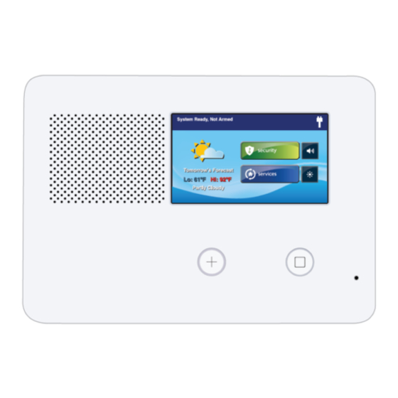
GC2e Wireless Security System | Installation and Programming Guide Control Panel Features External Features Figure 2 Control Panel External Features Sounds all system local alarms, voice prompts, system sounds, and audio for two (2)-way voice Alarm Sounder and Speaker communications with the Central Station Shows all system information, status, programming, and functions as the keypad. -
Page 11: Internal Features
GC2e Wireless Security System | Installation and Programming Guide Internal Features Figure 3 Control Panel Internal Features The standard backup battery that is included with all 2GIG Control Panels does not support UL Backup Battery Pack 985 installations. To comply with the secondary supply requirement in UL 985 Household Fire Warning System Units, you must install the 2GIG Console Battery Pack (2GIG-BATT2X). -
Page 12: Installation Outline
GC2e Wireless Security System | Installation and Programming Guide Installation Outline Use the following outline in conjunction with this Installation and Programming Guide to guide you through the installation steps. Unpack the system and identify the system components. Create an Installation Floor Plan to determine the best centralized location for the Control Panel. Decide where to best install the wired and/or wireless sensors. -
Page 13: Wireless Installation Tips
GC2e Wireless Security System | Installation and Programming Guide Wireless Installation Tips When installing any wireless system, consider certain limitations. Low power wireless transmitter signals do NOT broadcast equally through all types of construction materials. However, the Control Panel does contain a sensitive receiver that typically allows for placement of transmitters in nearly all locations. -
Page 14: Sensors And Accessories
GC2e Wireless Security System | Installation and Programming Guide Sensors and Accessories Wireless System Sensors • Thin Door/Window Contact • Recessed Door Contact • Passive Infrared (PIR) Motion Detector • Four (4)-Button Keyfob Remote • Panic Button Remote • Glass Break Detector •... -
Page 15: Installation
GC2e Wireless Security System | Installation and Programming Guide Installation Control Panel Mounting Plate Mount the Control Panel on the wall in a convenient location (or use the optional desk mount). These tools may be required to mount the Control Panel onto the wall: •... -
Page 16: Wireless Sensors
GC2e Wireless Security System | Installation and Programming Guide Installation Wireless Sensors Install wireless sensors in the appropriate location using the Installation Instructions included with each wireless sensor as a guide . Hardwired Loops Hardwired loops can be programmed either Normally Open (N/O) or Normally Closed (N/C). End-of-Line Resistors (EOLR) can also be used to supervise the loops . -
Page 17: Lte (Cellular) Radio Module
GC2e Wireless Security System | Installation and Programming Guide Installation Power ON the Control Panel . Figure 8 Attic Antenna Installation Access the System Configuration screen as follows: a . At the Home screen, tap the system logo in the lower-right corner. -
Page 18: Control Panel Wiring Diagram
GC2e Wireless Security System | Installation and Programming Guide Installation Control Panel Wiring Diagram The following diagram shows you the Control Panel wiring . Figure 10 Control Panel Wiring Diagram Copyright © 2018 Nortek Security & Control... -
Page 19: Control Panel Wiring
GC2e Wireless Security System | Installation and Programming Guide Installation Control Panel Wiring Backup Battery Connection and Power Supply Wiring The third-hand hanging strap allows you to hang the Control Panel on the mounting plate during installation. The backup battery connects to the Control Panel’s circuit board Hang the Control Panel on the mounting plate by the with a two (2)-pin header assembly. -
Page 20: Control Panel And Power Supply Mounting
GC2e Wireless Security System | Installation and Programming Guide Installation NOTE: In the United States, wiring routed inside walls, ceilings, Figure 14 Connecting Battery and Closing Panel and floors must comply with requirements of ANSI/NFPA 70: National Electrical Code (NEC) and local building codes . For wiring from the output of the 2GIG Class II Power Supply, wiring rated CL2, CL2X, CL2R, or PLTC is recommended to satisfy these requirements . -
Page 21: Commercial Installations
GC2e Wireless Security System | Installation and Programming Guide Commercial Installations For commercial installations, the Control Panel is designed for use only as a burglary alarm system, and not for fire protection. Installation location and wiring methods shall be in accordance with ANSI/NFPA 70: National Electric Code, UL 681: Installation and Classification of Burglar and Holdup Alarm Systems, and UL 827: Central‐Station Alarm Services . -
Page 22: Nfpa Standard 72
GC2e Wireless Security System | Installation and Programming Guide NFPA Standard 72 In the United States and Canada, smoke detectors must be installed in accordance with National Fire Protection Association (NFPA) Standard 72: National Fire Alarm and Signaling Code, which reads as follows: “2‐1.1.1 Smoke alarms shall be installed outside of each separate sleeping area in the immediate vicinity of the bedrooms and on each additional story of the family living unit including basements and excluding crawl spaces and unfinished attics. -
Page 23: Main Display Screens
GC2e Wireless Security System | Installation and Programming Guide Main Display Screens Home Screen • Trouble Alerts . Displays when trouble alerts are pending . To go to the Home screen, press the Home button on the • Messages . Displays when messages are pending . Control Panel . -
Page 24: System Status Screen
GC2e Wireless Security System | Installation and Programming Guide Menu Display Screens System Status Screen Figure 22 System Status Screen The System Status screen lists system status and any alerts . The date and time of alerts are listed in the displayed log. One option button for Silence is displayed;... -
Page 25: Toolbox And Installer Toolbox
GC2e Wireless Security System | Installation and Programming Guide Toolbox and Installer Toolbox The Control Panel includes two (2) different toolboxes for Figure 25 Toolbox (2 of 3) programming the system: • Toolbox . Individuals with a user code can access basic programming functions in the end user Toolbox. -
Page 26: System Configuration Screens
GC2e Wireless Security System | Installation and Programming Guide Toolbox and Installer Toolbox The System Configuration screens present installers with NOTE: The other buttons let you restore the default Control a sequential list of programming questions. For a list of all Panel settings and provide access to a variety of system tests. -
Page 27: System Status Icons
GC2e Wireless Security System | Installation and Programming Guide System Status Icons The top line of the Control Panel’s display is the status bar that shows the current system mode, the status of the sensors, and any current system trouble alerts. Special icons are displayed on the right side to provide visual indications of the system’s current condition. Figure 29 System Status Icons A Status Bar... -
Page 28: Programming Navigation
GC2e Wireless Security System | Installation and Programming Guide Programming Navigation When the installer is using the System Configuration menus, • The ↑ and ↓ arrows select the next or previous programming sub-question. the Control Panel will present each programming question sequentially. -
Page 29: Additional Buttons
GC2e Wireless Security System | Installation and Programming Guide Programming Navigation Additional Buttons Figure 42 Other Buttons Displayed Depending on the programming question, additional buttons may be displayed on screen: Tap Esc (Escape) to “undo” the previous action. This is •... -
Page 30: Programming Outline
GC2e Wireless Security System | Installation and Programming Guide Programming Outline Each system installed will require programming . Most After completing all setup and programming tasks, refer to the installations being performed by the professional alarm installer Control Panel’s User Guide for information about operating the for a specific organization will have common values set in every system. -
Page 31: Programming Question Table
GC2e Wireless Security System | Installation and Programming Guide Programming Question Table Programming Question/Sub-Question Default Setting Select RF Sensor # (01-48,63-74) Select RF Sensor # Type (00) Unused Varies by RF sensor type Select RF Sensor # Equipment Type Only shown for some sensor types Select RF Sensor # Equipment Code (0000) Other Enter RF Sensor # Other Equipment Code (0-9999) - Page 32 GC2e Wireless Security System | Installation and Programming Guide Programming Question Table Programming Question/Sub-Question Default Setting Select Siren Supervision Time (0 to 3) (0) Disabled Enter CS Lack of Usage Notification Time, in Days (0-255) 7 Days Enter Radio Modem Network Failure Time (0-255) 30 Minutes Select Radio Network Failure Causes Trouble (0 to 1) (1) Enabled...
- Page 33 GC2e Wireless Security System | Installation and Programming Guide Programming Question Table Programming Question/Sub-Question Default Setting Select monetary symbol (0 to 8) (0) $ Select Services Require Master Code (0) Disabled Select Master User Access to Z-Wave Toolbox (0 to 1) (0) Disabled Select Disable Siren After Two-Way Audio (0 to 1) (0) Disabled...
-
Page 34: Zone Numbering
GC2e Wireless Security System | Installation and Programming Guide Zone Numbering in mind: The Control Panel supports 60 wireless protection zones. When programming zones, keep the following numbering ranges Zones Descriptions 1-48 Wireless Zones 47-48 Wireless Cross-Sensor Zone 49-50 Wired Zones 51-58 Keyfobs 59-62... -
Page 35: Sensor Types (Zones)
GC2e Wireless Security System | Installation and Programming Guide Sensor Types (Zones) Each sensor (wireless or wired) installed in the system is programmed to a specific sensor number and sensor type (zone). The sensor number identifies the specific sensor when it is displayed on the Control Panel, recorded in the event log, or reported to the Central Station. -
Page 36: Sensor Type (Zone)
GC2e Wireless Security System | Installation and Programming Guide Sensor Types (Zones) Sensor Type (Zone) Description (32) Remote Device* This zone type is selected by the installer when pairing the panel with peripheral devices that can utilize localized troubles (such as RF jam, low battery, tamper, or AC loss detected by the peripheral device). This sensor is continuously active and will cause a trouble at the panel for all problem conditions. -
Page 37: Description
GC2e Wireless Security System | Installation and Programming Guide Voice Descriptors The Control Panel includes a system vocabulary. When programming sensors when using firmware version 1.13, you can use the codes detailed in this table: Figure 44 List of Voice Descriptors Code Description Code... - Page 38 GC2e Wireless Security System | Installation and Programming Guide Voice Descriptors Code Description Code Description Code Description Code Description SEVENTY TURN DAUGHTER’S OFFICE SHED TWELVE DOORBELL SHOP TWENTY GIRL’S SIDE IMAGE ONE HUNDRED SILENT UNLOCK IMAGE SENSOR OUTPUT SIREN UPPER MAIN OUTSIDE UPSTAIRS...
- Page 39 GC2e Wireless Security System | Installation and Programming Guide Equipment Codes The table below details the available equipment codes: Code Description (0000) Other (0470) HW R-D/W “5818MNL” (0475) Existing Glass Break Detector (0491) HW Panic Pendant “5802MN2” (0519) HW Glass Break “5853” (0530) HW PIR “5894PI”...
-
Page 40: Installer Programming
GC2e Wireless Security System | Installation and Programming Guide Installer Programming Account Registration • Q: Select RF Sensor # Equipment Code. Select the four (4)- digit equipment code for the sensor model . See “Equipment Register the account to enroll the Control Panel with the remote Codes”... -
Page 41: Q1: Rf Sensor Programming Outline
GC2e Wireless Security System | Installation and Programming Guide Installer Programming Q1: RF Sensor Programming Outline Summary of RF Sensor # Screen After setting all the options for a sensor, the RF sensor summary Figure 45 RF Sensor Programming Outline screen is displayed . - Page 42 GC2e Wireless Security System | Installation and Programming Guide Installer Programming • For automatic entry . Tap Shift, then tap Learn to place Sensor Types (Zone) Wired the Control Panel into learning mode . Then trigger the RF (08) 24-Hour Auxiliary Alarm* sensor.
-
Page 43: Wired Sensor Programming
GC2e Wireless Security System | Installation and Programming Guide Installer Programming Q: Construct RF Sensor # Voice Descriptor Code Sensor Chime Disabled DEFAULT: No Default Voice Only NOTE: For a list of available voice descriptors, see “Voice Ding-Dong with Voice #1 Descriptors”... -
Page 44: Summary Of Wired Sensor # Screen
GC2e Wireless Security System | Installation and Programming Guide Installer Programming Q2: Wired Sensor Programming Outline Summary of Wired Sensor # Screen After setting all the options for a sensor, the wired sensor Figure 47 Wired Sensor Programming Outline summary screen is displayed . The screen can also be displayed for programmed sensors during wired sensor program editing by tapping the Sum button. - Page 45 GC2e Wireless Security System | Installation and Programming Guide Installer Programming Q: Select Wired Sensor# Normal State Sensor Types (Zone) RF Sensors Wired Sensors DEFAULT: (0) Not Used (04) Interior Follower The two hardwired loops can be wired for normally open (N/O) or (05) Day Zone normally closed (N/C) contacts, or for end-of-line (EOL) resistor.
-
Page 46: Wireless (Rf) Key Fob Programming
GC2e Wireless Security System | Installation and Programming Guide Installer Programming Sensor Chime See Figure 49 Key Fob Programming Outline for the steps Code Sensor Chime required to program fobs into the Control Panel. The options Disabled that can be set for each fob are: Voice Only •... -
Page 47: Key Fob Programming Outline
GC2e Wireless Security System | Installation and Programming Guide Installer Programming Key Fob Programming Outline Summary of RF Key Fob # Screen After setting all the options for a key fob, the Summary of Fob # Q3: RF Key Fob Programming Outline screen is displayed . -
Page 48: Wireless (Rf) Keypad Programming
GC2e Wireless Security System | Installation and Programming Guide Installer Programming Q: Enter Fob # Serial Number (7 Digits) Q: Select Fob (#) Arm No Delay (0 to 1) DEFAULT: 0000000 DEFAULT: (0) Disabled Key fob serial numbers can be manually entered or learned from Key fobs can be set to arm the Control Panel with or without an the fob . -
Page 49: Rf Keypad Programming Outline
GC2e Wireless Security System | Installation and Programming Guide Installer Programming RF Keypad Programming Outline RF Keypad Programming Questions Q4: RF Key Pad Programming Outline Q4: Select RF Keypad # (1 to 4) Figure 50 Key Pad Programming Outline Up to four (4) wireless keypads can be programmed for use with each Control Panel. - Page 50 GC2e Wireless Security System | Installation and Programming Guide Installer Programming • The keypad displays “Network ID: xxxx” which is its unique serial number . • Tap OK on both the Control Panel and the Wireless • Touch Screen Keypad to continue. NOTE: The Wireless Touch Screen Keypad will display “The security system is temporarily not operational”...
-
Page 51: Control Panel Programming
GC2e Wireless Security System | Installation and Programming Guide Control Panel Programming Programming Questions Q13: 2-Way Voice (0-2) Q1: RF Sensor Programming DEFAULT: (1) Stay On Line The Control Panel supports two (2)-way voice communications To learn about RF sensor programming, see “Wireless (RF) between the subscriber and the Central Station operator over Sensor Programming”... -
Page 52: Q16: Police Emergency Key (0-2)
GC2e Wireless Security System | Installation and Programming Guide Control Panel Programming Q16: Police Emergency Key (0-2) Q21: Siren Supervision Time (0-3) DEFAULT: (1) Audible DEFAULT: (0) Disabled The Control Panel’s panic emergency button action can be The wiring connection to the external sounder can be programmed. -
Page 53: Q25: Radio Modem Network Failure Reports (0-1)
GC2e Wireless Security System | Installation and Programming Guide Control Panel Programming Q25: Radio Modem Network Failure Q31: Cancel Time, in Minutes (5-255) Reports (0-1) DEFAULT: 5 minutes The minimum setting for ANSI/SIA CP-01 compliance is 5 minutes. The DEFAULT: (1) Enabled number of minutes can be increased without affecting ANSI/SIA CP-01 NOTE: LTE (Cellular) Radio Module must be installed to use compliance . -
Page 54: Q38: Time To Detect Ac Loss, In Minutes (0-30)
GC2e Wireless Security System | Installation and Programming Guide Control Panel Programming Q35: Abort Window Dialer Delay (0-2) after the specified time length. When power is restored, the alert is automatically cleared after one (1) minute. DEFAULT: (1) 30 Seconds •... -
Page 55: Q45: Lock Default Programming (0-2)
GC2e Wireless Security System | Installation and Programming Guide Control Panel Programming Q45: Lock Default Programming (0-2) Q49: Programming Mode Entry Reports to CS (0-1) DEFAULT: (0) Default All The Control Panel may be able to be hard reset (or soft DEFAULT: (0) Disabled reset from the Installer Toolbox) to its factory default values A report can be sent to the Central Station any time installer... -
Page 56: Q53: System Low Battery Reports To Cs (0-1)
GC2e Wireless Security System | Installation and Programming Guide Control Panel Programming Q53: System Low Battery Reports to CS (0-1) Q59: Bypass Restore Reports to CS (0-1) DEFAULT: (1) Enabled DEFAULT: (0) Disabled Low battery reports can be sent to the Central Station if the Bypass restore reports can be sent to the Central Station Control Panel’s battery tests low. -
Page 57: Q64: Smart Test Reports
GC2e Wireless Security System | Installation and Programming Guide Control Panel Programming Q64: Smart Test Reports Q70: Daylight Saving End Sunday (1-7) DEFAULT: (0) Disabled DEFAULT: (1) 1st Sunday • The default setting (1) 1st Sunday defines the daylight Smart test reports are a way to reduce Central Station traffic. If saving end week . -
Page 58: Q75: Auto Unbypass For Manual Bypass (0-1)
GC2e Wireless Security System | Installation and Programming Guide Control Panel Programming Q75: Auto UnBypass for Manual Bypass (0-1) Q80: Z-Wave Switches Feature (0 to 1) DEFAULT: (1) Enabled DEFAULT: (1) Enabled Violated (open) sensors can be manually bypassed by the user Display of the Home Service’s Switches button can be enabled through the User Toolbox or force bypassed at the time of arming. -
Page 59: Q85: Master User Access To Z-Wave Toolbox (0-1)
GC2e Wireless Security System | Installation and Programming Guide Control Panel Programming Q85: Master User Access to Z-Wave Toolbox Q91: Radio Modem Supplier (0-1) DEFAULT: (0) No Radio Modem Supplier NOTE: If you enable Q44: Select Lock Installer Programming, DEFAULT: (0) Disabled you will not be able to change this setting. -
Page 60: Q93: Enter Broadband Network Failure Time (1-255)
GC2e Wireless Security System | Installation and Programming Guide Control Panel Programming Q: Select Port # (1 to 8) Q94: Select Broadband Network Failure DEFAULT: (1) Port 1 Causes Trouble (0 to 1) NOTE: Typically, you will skip this question unless additional programming is required . -
Page 61: Final Installation Setup
GC2e Wireless Security System | Installation and Programming Guide Final Installation Setup Exiting Programming (System Configuration) NOTE: User codes 0000, 0001, and the Installer Code are not permitted. After programming the Control Panel, all the changes need to be saved in memory. After saving, the programmed settings will remain Setup each user code with the User Access Option screen. - Page 62 GC2e Wireless Security System | Installation and Programming Guide Final Installation Setup At the Toolbox (2 of 3) screen, tap Set Date . Then use the ↓ and ↑ arrows to set the month, day, and year. When done, tap OK . Figure 55 Set Date Screen At the Confirmation screen, tap OK.
-
Page 63: Access The Installer Toolbox
GC2e Wireless Security System | Installation and Programming Guide Installer Testing Sensor Type (Zone) Report Test When installation and programming is complete, use the option in the Installer Toolbox to test for proper system To verify that the Central Station correctly receives reports operations. -
Page 64: Radio Status Test
GC2e Wireless Security System | Installation and Programming Guide Installer Testing Radio Status Test When the System Test: Sensors screen appears, you can tap the ↓ and ↑ arrows to scroll through the sensor list. If the LTE (Cellular) Radio Module is installed in the Control Figure 58 System Test: Sensors Screen Panel, use the Radio Status screen to view signal strength,... -
Page 65: Restore Default System Configuration
GC2e Wireless Security System | Installation and Programming Guide Installer Testing Restore Default System Configuration You can restore the Control Panel settings back to its factory defaults. There are two (2) types of reset options: Soft and hard . Soft Reset A soft‐reset lets you select which settings to restore back to the factory defaults . -
Page 66: Regulatory Information
GC2e Wireless Security System | Installation and Programming Guide Regulatory Information Wireless Product Notice Radio controls provide a reliable communications link and fill an important need in portable wireless signaling; however, there are some limitations which must be observed. • For U.S. -
Page 67: Commercial Regulatory Listings
GC2e Wireless Security System | Installation and Programming Guide Regulatory Information Commercial Regulatory Listings IMPORTANT: When used with the Alarm .com service, this security system has been evaluated and complies with UL 1610: Central‐ Station Burglar‐Alarm Units . It has not been evaluated for UL 864: Control Units and Accessories for Fire Alarm Systems and UL 1076: Proprietary Burglar Alarm Units and Systems. -
Page 68: Limited Warranty
GC2e Wireless Security System | Installation and Programming Guide Limited Warranty This Nortek Security & Control LLC product is warranted against defects in material and workmanship for one (1) year . This warranty extends only to wholesale customers who buy direct from Nortek Security & Control LLC or through Nortek Security &...
Need help?
Do you have a question about the 2GIG e Series and is the answer not in the manual?
Questions and answers