Teledyne 4700 Pocket Manual
Refrigerated sampler
Hide thumbs
Also See for 4700:
- Serivce manual (172 pages) ,
- Installation and operation manual (137 pages)
Table of Contents
Advertisement
Quick Links
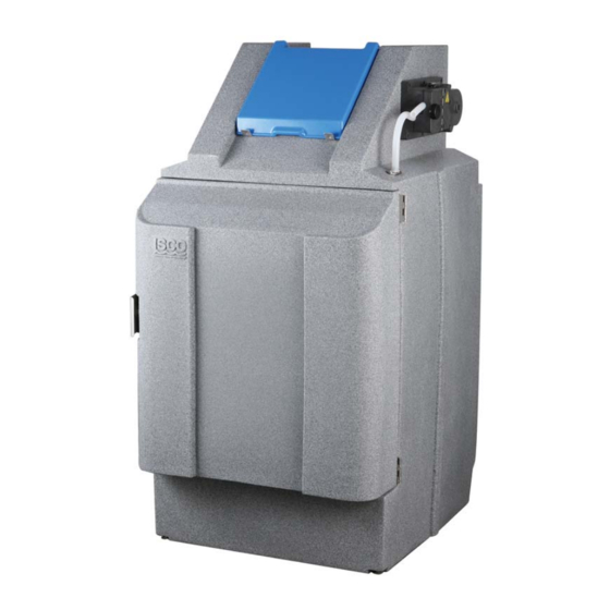
4700 Refrigerated
Sampler
This pocket guide is not intended to replace
the instruction manual. Read the instruction
manual thoroughly before operating the
sampler.
COPYRIGHT © 2003 by
Teledyne Isco, Inc.,
4700 Superior St.,
Lincoln, Nebraska, U.S.A. 68504
Phone: (402) 464-0231
Toll Free: (800) 228-4373
FAX: (402) 465-3022
Part #69-4703-085
Released: January 10, 2007
Advertisement
Table of Contents

Related Manuals for Teledyne 4700


Summary of Contents for Teledyne 4700
- Page 1 This pocket guide is not intended to replace the instruction manual. Read the instruction manual thoroughly before operating the sampler. COPYRIGHT © 2003 by Teledyne Isco, Inc., 4700 Superior St., Lincoln, Nebraska, U.S.A. 68504 Phone: (402) 464-0231 Toll Free: (800) 228-4373 FAX: (402) 465-3022 Part #69-4703-085...
-
Page 3: Table Of Contents
1.2 Specifications ....1-6 2. Installation 2.1 4700 Sampler Installation Overview 2-1 2.2 Positioning the Sampler ..2-1 2.3 Installing a Bottle Kit . - Page 4 2.8 Connecting Power ....2-30 2.9 Configuring and Programming the Sampler ..... . 2-31 2.10 Locking the Sampler .
- Page 5 Table of Contents 3.5.11 Volumes Dependent on Flow? ....3-35 3.5.12 Sample Volume __ ml ..3-36 3.5.13 Flow Pulses, Analog Input . . 3-36 3.5.14 10 ml for Every __ Pulses .
- Page 6 5. Maintenance 5.1 Periodic Maintenance Checklist ..5-1 5.1.1 Pump Inspection ... 5-2 5.1.2 Pump Tube Replacement ..5-4 5.1.3 Cleaning the Pump Rollers . . 5-7 5.1.4 Cleaning the Pump Housing .
-
Page 7: Introduction
4700 Refrigerated Sampler Section 1 Introduction 1.1 Features The 4700 Series sampler features are identified in Figures 1-1 through 1-3 and described in Table 1-1. Figure 1-1 4700 Sampler features (Front) - Page 8 4700 Refrigerated Sampler Figure 1-2 4700 Sampler features (Side) Figure 1-3 4700 Sampler features (Back)
- Page 9 Section 1 Introduction Table 1-1 4700 Sampler Features Item Name Description Control Protects the control panel Panel Cover display and keypad. Control Supports user control and Panel programming of sampler operation. Discharge Carries liquid to the Tube sample bottle. For 24, 4, 2,...
- Page 10 4700 Refrigerated Sampler Table 1-1 4700 Sampler Features (Continued) Item Name Description Latch Secures the door. The latch mechanism may be locked with a user-supplied padlock. Level The sampler includes two Adjustment level adjustment feet at the Feet front of the sampler. Use...
- Page 11 Section 1 Introduction Table 1-1 4700 Sampler Features (Continued) Item Name Description External Supports connections to Device external devices such as a Connection flow meter for sample pacing and enable signals, and connection to a personal computer for data collection.
-
Page 12: Specifications
4700 Refrigerated Sampler 1.2 Specifications Table 1-2 Specifications General 130 × 72 × 84 cm Size 51 × 28 × 33 in (H×W×D): Weight 72 kg (empty): 159 lb Bottle 12 configurations available: Configurations: 24, 1-liter PP or 350 ml glass;... - Page 13 Section 1 Introduction Table 1-2 Specifications (Continued) Maximum 2,000 meters Altitude: Humidity: 0 to 100% Operational –29 to 49 °C Temperature: –20 to 120 °F Pump Intake Suction 1 to 30 m Tubing Length: 3 to 99 feet Material: Vinyl or FEP-lined polyethylene Inside 9 mm Diameter:...
- Page 14 4700 Refrigerated Sampler Table 1-2 Specifications (Continued) Controller Enclosure IP67 Rating: NEMA 4X, 6 Program Non-volatile ROM (Flash) Memory: Flow Meter 5 to 15 volt DC pulse or 25 Signal Inputs: millisecond isolated contact closure for Isco flow meters. 4-20 mA input for non-Isco flow meters.
- Page 15 Section 1 Introduction Table 1-2 Specifications (Continued) Sample If no sample is detected, up to 3 Retries: attempts; user selectable. Rinse Cycles: Automatic rinsing of suction line up to 3 rinses for each sample collection. Controller Tests for RAM, ROM, pump, Diagnostics: display, and electrical components.
- Page 16 4700 Refrigerated Sampler 1-10...
-
Page 17: 4700 Sampler Installation Overview
4700 Refrigerated Sampler Section 2 Installation 2.1 4700 Sampler Installation Overview The following sections provide general instructions for placing the sampler into operation. In typical applications, the steps are: 1. Position the sampler. (Section 2.2) 2. Install a bottle kit. (2.3) 3. - Page 18 4700 Refrigerated Sampler The installation and use of this product may subject you to dangerous working conditions that can cause you serious or fatal injuries. Take any necessary precautions before entering the worksite. Install and operate this product in accordance with all applicable safety and health regulations, and local ordinances.
- Page 19 Section 2 Installation Appendix B of the Installation and Operation guide for a discussion of safety considerations. Support – The sampler should be installed on a surface capable of safely supporting the sampler, full liquid containers, and personnel. AC Power – The mains line cord is the disconnect device should you need to remove power.
- Page 20 4700 Refrigerated Sampler the line to drain, thereby reducing the possibility of sample cross-contamination. Refer to Table 1-2 for maximum suction line lengths and suction head heights. Security – The location may need to provide some degree of security to prevent tampering or vandalism.
-
Page 21: Installing A Bottle Kit
2.3 Installing a Bottle Kit The 4700 sampler can hold 1, 2, 4, and 24 bottles. Each of these bottle configurations are supplied as a kit (see Table 2-1), which is normally ordered with the sampler or when you desire to change the bottle configuration. - Page 22 4700 Refrigerated Sampler Table 2-1 Bottle Kits (Continued) Part Number Description 68-4700-005 4-bottle Configuration. Includes four polyethylene 10-liter round bottles with caps, locating base and two discharge tubes. 68-4700-006 4-bottle Configuration. Includes four glass 10-liter round bottles with PTFE lined caps, locating base and two discharge tubes.
- Page 23 Section 2 Installation Table 2-1 Bottle Kits (Continued) Part Number Description 68-4700-018 Single ProPak Configuration for 4700 and 6700 Series FR Refrigerated Sampler. Includes one composite ProPak holder with cap, 100 ProPak bags, two discharge tubes and an instruction sheet.
-
Page 24: Installing The Distributor Arm And Discharge Tube
4700 Refrigerated Sampler 2.3.1 Installing the Distributor Arm and Discharge Tube The distributor arm ships with the sampler installed on its mounting shaft inside the refrigerator (Figure 2-1). It is generally easier to install the discharge tube with the arm removed, then you can reinstall the distributor arm. - Page 25 Section 2 Installation CAUTION The discharge tube should not extend below the hole in the distributor arm. This could cause the distributor to fail if the excess tubing catches a bottle. 5. Pull on the loose end of the discharge tube to remove any slack.
-
Page 26: Bottles
4700 Refrigerated Sampler the tube and cross-contaminate samples. Note that the discharge tube has a natural curve. Should the tube create a low spot where liquid can pool, twist the end of the tube connected to the bulkhead fitting so that the natural curve holds the tube in a downward sloping position. - Page 27 Section 2 Installation Figure 2-2 Insert the keyed end first so that it faces the back of the refrigerated compartment Figure 2-3 The 24-bottle rack is held in place by a latch on the left side 2-11...
-
Page 28: Bottles
4700 Refrigerated Sampler Note There are four metal guides along the sidewall of the refrigerator, two on each side. The front two guides fit along the left and right sides of the rack. The back two guides run along the top of the rack to prevent the rack from tipping forward. - Page 29 Section 2 Installation Figure 2-4 Installing the locating base 2. Insert the two uncapped bottles into the holes numbered “1” and “2” in the locating base. Note When the sampler controller is configured for two bottles (section 3), samples will only be distributed to bottles 1 and 2.
-
Page 30: Bottle
4700 Refrigerated Sampler 2.3.5 1 Bottle If your one-bottle configuration has a 10 liter (2.5 gallon) polyethylene, glass, or ProPak bottle, use a locating base to hold and align the bottle. If your one-bottle configuration has a 20 liter (5 gallon) glass or polyethylene bottle, simply place the bottle in the center of the refrigerator;... - Page 31 Section 2 Installation 3. Store the arm in a safe location for future use. Then install the bottle: 4. Screw the cap with a hole onto the bottle. 5. Place the bottle in the center of the refrigerator. 6. Feed the discharge tube into the hole (see Figure 2-5).
-
Page 32: Attaching The Suction Line
The sampler uses a -inch ID suction line of lengths from 3 to 99 feet. Teledyne Isco offers vinyl or FEP-lined suction lines. The FEP-lined tubing has a polyethylene jacket to protect it from kinks and abrasions. -
Page 33: Vinyl Suction Line
Section 2 Installation suction line will hold liquid between sample events which could cross-contaminate samples or freeze in cold climates. If the standard lengths are too short, or if you are cutting compatible -inch ID suction line from a bulk spool, you can use lengths up to 30 m (99 ft). - Page 34 4700 Refrigerated Sampler 4. Secure the vinyl suction line connection by wrapping the white clamp around the tube and squeezing the finger pads together. Figure 2-6 Attaching the vinyl suction line with a tube coupler Note Release clamps by sliding the finger pad ends in opposite directions until the teeth disengage (Figure 2-7).
-
Page 35: Fep-Lined Suction Line
Section 2 Installation 2.4.2 FEP-lined Suction Line Inserting a tube coupler into FEP-lined suction line will damage the thin lining. Instead, refer to Figure 2-8 and the instructions below to attach FEP-lined suction line to the pump tube: 1. Slide a suitable clamp over the pump tube inlet. - Page 36 4700 Refrigerated Sampler øA Low Flow 69-2903-138 Weighted 60-9004-367 CPVC 60-3704-066 øB Figure 2-9 Strainers 2-20...
- Page 37 Section 2 Installation 2-21...
-
Page 38: Alternative To Strainers
4700 Refrigerated Sampler 2.5.1 Alternative to Strainers When sampling from high velocity streams with heavy suspended solids, some field investigations suggest that more representative samples are obtained without the strainer. Consider attaching a short piece of thin walled aluminum tubing to the end of the suction line;... -
Page 39: Routing The Suction Line And Strainer
Section 2 Installation 2.6 Routing the Suction Line and Strainer Route the suction line so that it has a continuous slope from the liquid source to the sampler. This helps to drain the line during pre- and post-sample line rinses. If a suction line exposed to freezing climates does not fully drain, there is a risk of liquid in the suction line becoming frozen. - Page 40 4700 Refrigerated Sampler Figure 2-10 External device connection at rear of sampler • Receiving an enable pin signal to enable sampler operation once site conditions warrant sample collection. • Sending a three-second event mark at the beginning of every sample collection event.
-
Page 41: Standard Isco Instrument Connections
To connect either of these instruments, use the optional 7.6 m (25 ft) connect cable, 69-4704-043 (Figure 2-11). Figure 2-11 4700 Sampler to Isco flow meter cable 2.7.2 Other Device Connections You can connect the sampler to receive a 4-20 mA signal from an external device, including Isco’s 2108 and accQcomm™... - Page 42 12 VDC power. All of these types of connections use the optional unterminated connect cable, P/N 68-4700-020 (Figure 2-12). This 3 m (10 ft) cable is unterminated at the device end to allow wired connections to compatible circuits. Refer to Table 2-3 for wire identification and connection details.
- Page 43 Section 2 Installation The Isco Quick Disconnect (Q.D.) box, P/N 60-2004-228, can provide a convenient, watertight connection to wiring from a non-Isco device. The sealed IP67 (NEMA 4x) enclosure contains seven terminal blocks and is equipped with a mounting plate. The hazardous location rating of Q.D.
- Page 44 4700 Refrigerated Sampler Table 2-3 Unterminated Connect Cable (Continued) Pin Wire Signal Parameters/ Name Comments Color Enable Input: Ground this input (short to pin 2) to disable sampler operation. Leave this input open (floating) to collect samples. White/Black 12 VDC Output: +12.5 VDC,...
- Page 45 Section 2 Installation Table 2-3 Unterminated Connect Cable (Continued) Pin Wire Signal Parameters/ Name Comments Color 13 Blue/White Analog Input: See pin 12. 4-20 mA (–) 14 Blue/Black Ground Common ground. Same as pin 2. 15 Black/White Not used 16 Bare Not used a.
-
Page 46: Connecting Power
4700 Refrigerated Sampler 2.8 Connecting Power WARNING Before connecting the sampler to an AC power source, be familiar with the Electrical Requirements listed at the front of the Installation and Operation manual. The factory assembles the sampler for either 100VAC/50 Hz, 115 VAC/60 Hz, or 230 VAC/50 Hz. -
Page 47: Configuring And Programming The Sampler
Section 2 Installation 2.9 Configuring and Programming the Sampler To complete the installation, the sampler software should be configured and programmed. Refer to Section 3 for instructions. Configure the sampler to make sure that it “knows” what bottle configuration is installed, the length of the suction line, etc. - Page 48 4700 Refrigerated Sampler 2-32...
-
Page 49: Programming
4700 Refrigerated Sampler Section 3 Programming 3.1 Control Panel Description Figure 3-1 Control Panel Buttons Table 3-1 Control Buttons Icon Name Description Power Places the sampler in the On or Standby modes. Note: In either mode, mains power is always connected to the refrigeration system. - Page 50 4700 Refrigerated Sampler Table 3-1 Control Buttons Icon Name Description Press this button to start Program the sampling program. Number Types a number. Buttons Pump At the Main menu, press Reverse this button to run the (Purge) pump in the reverse direction to purge the suction line.
-
Page 51: Getting Started
(manual) sample. Enter Accepts a menu choice or number entry and goes to next screen. 3.2 Getting Started Apply power to the sampler (see section 2.8). The start-up screens appear on the LCD display. Copyright 2006 TELEDYNE ISCO 4700 SAMPLER... -
Page 52: Configuring The Sampler
4.3.1) will not contain meaningful data until you have run a sampling program. 3.3 Configuring the Sampler Before operating the 4700 Sampler, configure the sampler software. Doing so will set the time and date, and allow the sampler controller to correctly use the hardware and external connections. -
Page 53: Set Clock
Section 3 Programming or change the settings for the displayed option, press the Enter button. The sampler will return to the SELECT OPTION <– –> screen when there are no more settings for the selected option. To return to the SELECT OPTION <–... -
Page 54: Suction Line
4700 Refrigerated Sampler options and control the operation of the distributor. SELECT OPTION: (<-->) BOTTLES AND SIZES Select the BOTTLES AND SIZES option and press Enter. NUMBER OF BOTTLES: Press the Previous or Next buttons to highlight the installed bottle configuration. -
Page 55: Liquid Detector
Section 3 Programming Select the SUCTION LINE option and press Enter. SUCTION LINE LENGTH: ___ ft (3-99) Press the Number buttons to enter the suction line length. PLEASE WAIT! CREATING PUMP TABLES The sampler creates pump tables before returning to the SELECT OPTION <– –> screen. - Page 56 4700 Refrigerated Sampler Select YES (the factory default) for improved sample volume accuracy, and to enable Rinse Cycles and Sampling Retries. Select NO to turn off all of these features and return to the SELECT OPTION <- -> screen. __ RINSE CYCLES...
-
Page 57: Flow Mode Sampling
Section 3 Programming 3.3.5 Flow Mode Sampling Select this option to indicate whether or not the sampler should take a sample when the Run Program button is pressed. The Sample At Start option is only applicable to Flow Paced programs. SELECT OPTION: (<-->) FLOW MODE SAMPLING Select the FLOW MODE SAMPLING... -
Page 58: Enable Pin
4700 Refrigerated Sampler 3.3.6 Enable Pin Select this option to specify which actions the sampler controller should take when the Enable Pin state changes. The Enable Pin feature allows an external device (section 2.7) to control the running programs. SELECT OPTION: (<-->) -
Page 59: Refrigeration
Section 3 Programming The sampler controller is disabled when pin 6 of the External Device connector is held at ground potential. Isco devices do this by shorting pins 6 (Enable) and 2 (GND) together. A non-Isco device can disable the sampler by using a relay contact closure to short these two pins together. -
Page 60: Output Pins
4700 Refrigerated Sampler quite useful when collecting warm liquids or larger sample volumes to draw down the temperature quickly. To prevent the sample from freezing, Quick Cool will not lower the target temperature below 0.5°C. 3.3.8 Output Pins Select this option to configure the four alarm outputs. - Page 61 For more information about the optional Three-way valve option and sampling from pressurized lines, contact your Isco dealer or the Teledyne Isco factory. To configure the alarm output pins: SELECT OPTION: (<-->) OUTPUT PINS Select the OUTPUT PINS option and press Enter.
-
Page 62: Tubing Life
4700 Refrigerated Sampler 3.3.9 Tubing Life Select this option to view and reset the pump counts. The Tubing Life feature serves as a reminder so you can replace the pump tube at regular intervals before its wall cracks and ruptures. Several problems may arise from a weak or ruptured pump tube: •... - Page 63 Section 3 Programming The sampler counts pump revolutions in both the forward and reverse cycles with a resettable counter. When the counter reaches the default of 500,000 counts, the sampler displays an alert message, “WARNING! REPLACE PUMP TUBE.” After replacing the pump tube (see section 5.1.2), reset the count to zero so the sampler can begin tallying the pump counts for the new tube.
-
Page 64: Program Lock
A properly maintained sampler will provide years of reliable service that is expected of a Teledyne Isco Sampler. 3.3.10 Program Lock Select this option to turn the Program Lock feature on or off, and to change the password. -
Page 65: Language
Should you forget the password, contact Teledyne Isco’s Customer Service department for assistance. 3.3.11 Language Select this option to change the display language and display units for length measurements. -
Page 66: System Ids
4700 Refrigerated Sampler SELECT LANGUAGE (<-->) ENGLISH Press the Next or Previous buttons to scroll through the options. Press the Enter button when the desired option is displayed. If you select a language other than English, the sampler automatically displays length or distance units as meters and returns to the SELECT OPTION <–... -
Page 67: Run Diagnostics
Section 3 Programming HARDWARE: ___ SOFTWARE: _._ This screen lists the version numbers of the installed hardware and software. Press the Enter button to return to the SELECT OPTION <– –> screen. 3.3.13 Run Diagnostics Select this option to enter the sampler diagnostics mode to test the sampler memory, display, keypad, pump, distributor, and various inputs and outputs. - Page 68 4700 Refrigerated Sampler • your programmed number of flow pulses has been reached, or • a disabled sampler becomes enabled (section 3.3.6). At each event, the sampler: 1. Resets the programmed flow or time pacing interval. 2. Moves the distributor arm over the next bottle.
- Page 69 Section 3 Programming There are four categories of sampling program instructions that control the above actions in an event: • Pacing instructions define what controls the sample collection interval and its frequency. • Distribution instructions define where the collected liquid sample is placed. Single-bottle samplers can only distribute the sample to the composite bottle therefore skip the steps in this category.
- Page 70 4700 Refrigerated Sampler PROGRAM CONFIGURE VIEW LOG Pacing TIME PACED FLOW PACED Distribution 3.5.1 Multiple Bottles SAMPLE EVERY __ BOTTLES PER __ HOURS, __ MINUTES SAMPLE EVENT (1-max) 3.5.2 3.5.4 __ SAMPLES PER One Bottle BOTTLE (1-max) 3.5.8 RUN CONTINUOUSLY? 3.5.9...
- Page 71 Section 3 Programming Volumes Continued One Bottle Multiple Bottles __ COMPOSITE SAMPLES (0-max) 3.5.16 SUCTION HEAD: If Applicable __ ft (0-max) 3.5.17 Start Time NO DELAY TO START SET START TIME 3.5.18 FIRST SAMPLE AT: HH:MM DD-MON 3.5.19 PROGRAMMING SEQUENCE Displayed for 4 seconds COMPLETE…...
- Page 72 4700 Refrigerated Sampler PROGRAM CONFIGURE VIEW LOG Pacing TIME PACED FLOW PACED 3.5.1 SAMPLE EVERY __ PULSES (1-9999) 3.5.3 Distribution One Bottle Multiple Bottles __ BOTTLES PER SAMPLE EVENT (1-max) 3.5.4 SWITCH ON TIME SWITCH BOTTLES EVERY NUMBER OF SAMPLES __ HOURS, __ MINUTES 3.5.5...
- Page 73 Section 3 Programming Volumes Continued One Bottle Multiple Bottles __ COMPOSITE SAMPLES (0-max) 3.5.16 SUCTION HEAD: __ ft (0-max) if applicable 3.5.17 Start Time NO DELAY TO START SET START TIME 3.5.18 START FLOW COUNT AT: HH:MM DD-MON 3.5.20 MAXIMUM RUN TIME ___ HOURS 3.5.21 PROGRAMMING SEQUENCE...
-
Page 74: Programming Steps
4700 Refrigerated Sampler 3.5 Programming Steps To begin programming from the Main Menu screen, use the Next or Previous button to select PROGRAM. Press the Enter button to display the first programming screen. Refer to Figures 3-2 through 3-5 and the following descriptions. -
Page 75: Sample Every
Section 3 Programming All Isco flow meters provide a compatible flow pulse. Non-Isco flow measurement devices may be used to paced the sampler. Refer to section 2.7, Connecting the Sampler to External Devices for more details. Use the Next or Previous buttons to select the time or flow option, then press the Enter button. - Page 76 4700 Refrigerated Sampler every 10,000 gallons, you would enter 100 flow pulses. 10,000 gallons ÷ 100 gallons = 100 pulses If the flow measurement device sends flow rate data via a 4-20 mA current loop instead of flow pulses, the sampler converts this analog current to flow pulses representative of a volume.
- Page 77 Section 3 Programming Table 3-2 Flow Pulse Intervals at Various Input Currents Input Seconds % of Full Current (mA) Between Scale Flow Pulses Rate ∞ (no pulses) 6.25 12.5 18.75 38.4 31.25 37.5 27.4 43.75 21.3 56.25 19.2 62.5 17.4 68.75 14.8 81.25...
- Page 78 4700 Refrigerated Sampler The steps can be summarized in the equation below. ÷ (Q ÷ F ) = Number of pulses samp time Note The equation requires similar units for Q and I samp That is, the volume and flow rate units must use the same basic unit (cubic feet and cubic feet per second, gallons and gallons per minute, etc.).
-
Page 79: Bottles Per Sample Event
Section 3 Programming either the flow rate to gallons per day or your sample interval to millions of gallons. (The example below shows the flow rate converted to gallons per day.) After completing the equation you would enter 9 flow pulses. 10000 gal ÷... -
Page 80: Switch On Time Or Number
4700 Refrigerated Sampler 3.5.5 Switch on Time or Number of Samples Flow Paced, Multiple Bottles Only – The sampler can switch bottles at regular time intervals or switch after a specified number of samples. Use the Next or Previous buttons to select your choice. - Page 81 Section 3 Programming following diagrams illustrate the effect of this number. Distribution scheme with one sample per bottle. Sample events are numbered. Distribution scheme with two samples per bottle. Distribution scheme with three samples per bottle. This Samples per Bottle feature can be combined with the Bottles per Sample Event (section 3.5.4) to build more complex distribution schemes, sometimes known as...
-
Page 82: Run Continuously
4700 Refrigerated Sampler 3.5.9 Run Continuously? Multiple Bottles Only – Sample programs can run indefinitely by selecting YES at the RUN CONTINUOUSLY? screen. Continuous sampling resets the distribution when the distribution sequence is complete. That is, when the last bottle/set is reached, the next bottle/set is the first bottle/set. -
Page 83: Volumes Dependent On Flow
Section 3 Programming will use these settings and vary the sample collection cycle to deliver the entered sample volume at any suction head height. To view or change the entered sample volume, use the Next or Previous button to select ENTER SAMPLE VOLUME. -
Page 84: Sample Volume
4700 Refrigerated Sampler sampling, select YES. To use fixed sample volumes, select NO. 3.5.12 Sample Volume __ ml This screen displays the defined sample volume. Use the Number buttons to enter the sample volume. Press the Enter button to accept the displayed value. -
Page 85: Sample Volume At 20 Ma
Section 3 Programming 3.5.15 Sample Volume at 20 mA: __ ml Time Paced Only – If you selected ANALOG INPUT to determine the sample volume (section 3.5.13), use the Number buttons to enter the sample volume to be collected at the maximum flow rate, 20 mA. -
Page 86: Suction Head
To measure the suction head height, refer to Figure 3-6. For most applications, Teledyne Isco recommends that you turn on the liquid detector (section 3.3.4). The sampler will automatically calculate the suction head height, typically resulting in more accurate and repeatable sample volumes. -
Page 87: No Delay To Start Set Start Time
Section 3 Programming Applications that collect samples from a pressurized line are an exception. Teledyne Isco offers a pressurized line option for the sampler. Contact the factory for more information. When using Teledyne Isco’s pressurized line option, disable liquid detection and enter “1” at the suction head screen. -
Page 88: First Sample At
4700 Refrigerated Sampler 3.5.19 First Sample At: Time Paced Only – Use the Number buttons to set the start time hours. Press the Enter button to accept the value and advance to the minutes. Repeat to complete the minutes, date, and month. -
Page 89: Programming Examples
Section 3 Programming 3.6 Programming Examples Sections 3.6.1 through 3.6.4 provide programming examples. 3.6.1 Defining the Sample Volume If you have programmed the sampler to USE DEFINED SAMPLE (section 3.5.10), follow the steps in this example to define the volume using pump counts. - Page 90 4700 Refrigerated Sampler To change the pump counts, use the Number buttons to type the pre-purge counts. Or, press and hold the “1” button to reset the count to zero and start the pump in reverse to purge the line. Hold the 1 button until the line is sufficiently purged.
- Page 91 Section 3 Programming ___ COUNT POSTPURGE HOLD '1' TO PURGE The sampler displays the post-purge screen to define number of counts needed to purge the suction line. Use the Number buttons to type the post-purge counts. Or, press and hold the “1” button to reset the count to zero and start the pump in reverse to purge the line.
-
Page 92: Time Paced Sampling Program
4700 Refrigerated Sampler 3.6.2 Time Paced Sampling Program This example shows how to program the sampler to collect a 500 ml sample every hour for twenty-four hours. The sampler will place each discrete sample in a separate bottle. The sampling program should take the first sample at 8:00 am on the current day. - Page 93 Section 3 Programming ___ BOTTLES PER SAMPLE EVENT (1-max) The sampler displays the Bottles Per Sample Event screen. Because our program requires one bottle for each sample event, type “1” using the Number button and press Enter. ___ SAMPLES PER BOTTLE (1-max) The sampler displays the Samples Per Bottle screen.
- Page 94 4700 Refrigerated Sampler SAMPLE VOLUME: ___ ml (10-max) The sampler displays the Sample Volume input screen. Type “500” using the Number buttons and press Enter. NO DELAY TO START SET START TIME The sampler displays the Start Time option screen. Select SET START TIME and press Enter.
-
Page 95: Flow Paced Sampling Program
Section 3 Programming 3.6.3 Flow Paced Sampling Program This example shows how to program the sampler to collect a 100 ml sample every 10,000 gallons of liquid that has passed the sampling point. The sampler will composite the samples in one of its two 10-liter bottles. The sampling program should begin counting the elapsed flow at midnight and run continuously. - Page 96 4700 Refrigerated Sampler SAMPLE EVERY ___ PULSES (1-9999) The sampler displays the pacing interval screen. Type “10” using the Number buttons. Given that the flow meter sends one flow pulse every 1,000 gallons, this would equate to a sample event every 10,000 gallons.
- Page 97 Section 3 Programming FIRST SWITCH TIME AT HH:MM The sampler displays the First Switch Time screen. Our program must switch bottles at midnight. Type “0” for the hours and press Enter. Then, type “0” for the minutes and press Enter. RUN CONTINUOUSLY? The sampler displays the Run Continuously screen.
- Page 98 4700 Refrigerated Sampler START FLOW COUNT AT: HH:MM DD-MON The sampler displays the Start Flow Count screen. Type “00” and press Enter, then type “00” and press Enter again (12:00 am in 24-hour time format). Type the number for tomorrow’s day and press Enter.
-
Page 99: Flow-Proportional Constant Time Variable Volume Program
Section 3 Programming 3.6.4 Flow-proportional Constant Time Variable Volume Program This example shows how to program the sampler to collect flow-proportional samples volumes at fixed time intervals. This program will collect a sample every 15 minutes. The sample volume will be dependent on a 4-20 mA flow rate input signal, which will collect a 100 ml sample at 1.0 m s. - Page 100 4700 Refrigerated Sampler TIME PACED FLOW PACED The sampler displays the Time or Flow pacing option screen. Use the Next or Previous button to select TIME PACED. Then press the Enter button. SAMPLE EVERY ___ HOURS, ___ MINUTES The sampler displays the pacing interval screen.
- Page 101 Section 3 Programming SAMPLE VOLUME AT 20 mA: ___ ml The sampler displays a screen to set the sample volume to collect at the maximum flow rate. Type “100” and press Enter. ___ COMPOSITE SAMPLES (0-max) The sampler displays the Composite Samples screen.
- Page 102 4700 Refrigerated Sampler 3-54...
-
Page 103: Operation
4700 Refrigerated Sampler Section 4 Operation This section describes how to operate the sampler. These instructions assume that the sampler has been correctly installed (section 2), configured, and programmed (section 3). 4.1 Start a Sampler Program Before starting a program: •... -
Page 104: Start Time Delay
4700 Refrigerated Sampler Using the Number buttons, enter the starting bottle. Then press the Enter button. 4.1.1 Start Time Delay If the program is set for NO DELAY TO START (section 3.5.18), The sampler immediately begins to operate according to its Configure and Program settings. -
Page 105: The Run State
Section 4 Operation 4.1.2 The Run State Because the sampler operation is fully automated, no user intervention is required. Should there be a need to check on the running program, you can view the sampler display. It always reports the current state or operation and the refrigerator temperature. -
Page 106: Completed Program
4700 Refrigerated Sampler 4.1.3 Completed Program When the program is complete, the display will show PROGRAM DONE and list the number of samples. If the sampler encounters an error at any time during the running program, this display will alternate with an “ERRORS HAVE OCCURRED”... -
Page 107: Post Sampling Activities
Section 4 Operation to exit the paused state and resume the program. During the pause, you can reset the countdown timer to five minutes by pressing the Number, Next, or Previous buttons. Note While paused, the sampler skips sample events that would have occurred otherwise. - Page 108 4700 Refrigerated Sampler While viewing the log, you can: • Step forward through the screens by pressing the Next or Enter buttons. • Step backward by pressing the Previous button. • Exit the log by pressing the Stop button. The log generally contains the following...
- Page 109 Section 4 Operation PROGRAM HALTED HH:MM DD-MON-YY If the program was halted before the programmed completion time, the log reports the time. PROGRAM PAUSED ___ SAMPLES REMAIN If you are viewing the log while the program is paused, the log displays the number of samples that remain.
- Page 110 4700 Refrigerated Sampler CLOCK SET AT HH:MM DD-MON-YY The log reports the last time the clock was set. 4700 SAMPLER ID: ___________ The log reports the unique ID for the sampler control panel. This identifier is assigned at the factory.
- Page 111 Section 4 Operation Table 4-1 4700 Errors Message Description No Liquid The sampler was unable to Detected detect liquid. No More Liquid After the sampler detected liquid and while the sample was being taken, the liquid detector stopped detecting liquid.
-
Page 112: Remove Sample Bottles
4700 Refrigerated Sampler 4.3.2 Remove Sample Bottles After the program is complete, the bottles can be removed and prepared for the laboratory. Gain access to the bottles by releasing the door latch and swinging the door open. The bottles can then be removed from the rack or locating base. -
Page 113: Grab Samples
Section 4 Operation Figure 4-1 Sliding the 24-bottle rack out 4.4 Grab Samples Grab samples let you take a single sample on demand and collecting it in an external container. You can collect a grab sample while the sampler is running a program, paused, or at the Main Menu screen. -
Page 114: Calibrate Sample Volumes
4700 Refrigerated Sampler select the ENTER SAMPLE VOLUME, then use the Number buttons to enter the desired grab sample volume. Note If you selected the USE DEFINED SAMPLE option, the sampler will collect the sample volume according to the DEFINED SAMPLE calibration setting. For more information on this feature see section 3.6.1. - Page 115 (section 2) and the suction line has been cut and its length entered in the sampler configuration (section 3.3.3). These steps also require a graduated cylinder to measure the delivered sample volume. Teledyne Isco offers a 1000 ml graduated cylinder. Order part number 299-0020-00. To calibrate the sample volume:...
- Page 116 4700 Refrigerated Sampler CALIBRATE VOLUME: ↵ PRESS WHEN READY! Pull the lower pump tube from the bulkhead fitting. Hold the end of the tube over the graduated cylinder. Press the Enter button when you are ready. TAKING ___ ml CALIBRATE SAMPLE Hold the graduated cylinder while the sampler collects the sample.
-
Page 117: Operate The Pump Manually
Section 4 Operation 4.6 Operate the Pump Manually The sampler pump can be operated manually from the Main Menu display. To operate the pump: 1. Press the “1” Number button to prepare the pump for reverse operation (line purge). ↵ PRESS PUMP REVERSE Or, press the “3”... - Page 118 4700 Refrigerated Sampler 4-16...
-
Page 119: Maintenance
This section describes how to maintain your sampler. If you think your sampler requires repair, or if you have questions concerning its operation or maintenance, contact your authorized Isco service facility or Teledyne Isco’s Technical Service Department: Phone: (800) 228-4373 (402) 464-0231 (international) -
Page 120: Pump Inspection
4700 Refrigerated Sampler 5.1.1 Pump Inspection Inspect the pump before each use. Inspections are especially important when pumping large sample volumes over long distances or when the sample liquid contains a high percentage of suspended or abrasive solids. Pumps in need of... - Page 121 Section 5 Maintenance Figure 5-1 4700 Pump Pump Tube Bulkhead Fitting Tubing Connector Clamps Alignment Notches Alignment Collars Liquid Detector Cover Latch Knob Pump Housing Pump Housing Band 3. Swing the pump housing band away from the pump housing. 4. Inspect the following: Pump tube –...
-
Page 122: Pump Tube Replacement
4700 Refrigerated Sampler ent unless you flex or squeeze the tubing. If cracks or excessive wear are evident, replace the pump tube (section 5.1.2). Pump Rotor – Look for debris build-up on the pump roller or guide surfaces (Figure 5-2). Clean when needed (section 5.1.3). - Page 123 Section 5 Maintenance be used. Incorrect pump tubing may result in poor pump performance or even cause parts to fail prematurely. Also note that the discharge tube is not the same as the pump tube. Refer to Figure 5-1 and the following steps to replace the pump tube.
- Page 124 4700 Refrigerated Sampler 7. Align the blue collars with the alignment notches. 8. Close the liquid detector cover and secure it tightly with the large knob. 9. Close the pump housing band and secure it with the latch. 10. Reset the pump-tube counter. (Follow the steps in section 3.3.9 and select YES when...
-
Page 125: Cleaning The Pump Rollers
Section 5 Maintenance • Minimize the line rinses and sampling retries in the sampling programs. • Use the shortest possible suction line. 5.1.3 Cleaning the Pump Rollers Debris should be removed from the rollers and guides to keep the pump operating efficiently and to extend tubing life. - Page 126 4700 Refrigerated Sampler delivery system. Next, place the strainer in clean water and pump it through the delivery system to rinse it. If these items are severely contaminated, replace them. Figure 5-3 Wetted Parts Strainer (316 stainless steel, polypropylene, or CPVC)
-
Page 127: Sampler Cleaning Guidelines
Section 5 Maintenance For application-specific requirements, consult with your laboratory to establish cleaning or replacement protocols. 5.1.6 Sampler Cleaning Guidelines Keeping the sampler clean and protected from harsh elements may extend the usable life of the sampler. When necessary, clean the exterior and interior of the sampler with warm soapy water and brush, then rinse with water. - Page 128 4700 Refrigerated Sampler 5-10...
Need help?
Do you have a question about the 4700 and is the answer not in the manual?
Questions and answers