Advertisement
Quick Links
ASX-560 / ASX-280 Autosampler
Installation Guide for
Cytiva ÄKTA™ Systems
Manual Part Number 480237 Rev 3
Use and Disclosure of Data
Information contained herein is classified as EAR99 under the U.S. Export Administration Regulations.
Export, reexport or diversion contrary to U.S. law is prohibited.
Advertisement

Subscribe to Our Youtube Channel
Related Manuals for Teledyne ASX-560


Summary of Contents for Teledyne ASX-560
- Page 1 ASX-560 / ASX-280 Autosampler Installation Guide for Cytiva ÄKTA™ Systems Manual Part Number 480237 Rev 3 Use and Disclosure of Data Information contained herein is classified as EAR99 under the U.S. Export Administration Regulations. Export, reexport or diversion contrary to U.S. law is prohibited.
- Page 2 This guide will help you install your new autosampler and associated software in order to connect with the Cytiva Ä KTÄ system. The ASX-560/ASX-280 Autosampler Operator’s Manual, which you can find on the included USB flash drive, provides more information on every aspect of setting up the autosampler for a standard ICP application.
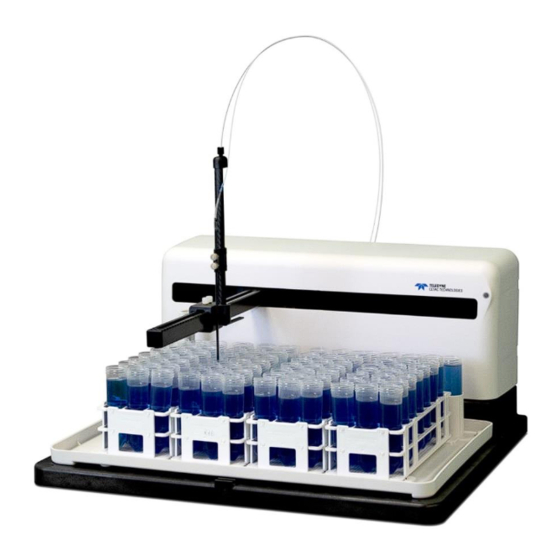
- Page 3 Autosampler Components Z-Drive Assembly Power Indicator Lamp Rinse Station Standards Vials Sample Tray Sample Vial Racks Power Switch Auxiliary Port Serial Ports USB Port Peristaltic Pump Power Connector Z-Drive Rotor EAR99 Technology Subject to Restrictions Contained on the Cover Page.
-
Page 4: Before You Begin
If you have not already evaluated the intended location for the autosampler, see the ASX-560/ASX-280 Operator’s Manual on the USB flash drive. Step 2: Unpack the Autosampler Do not lift the autosampler by its arm. The arm contains precision mechanical components which may be damaged if the arm is bent or twisted. - Page 5 Step 3: Install the ASX Dashboard Software On the included USB flash drive, double-click the ÄSX Dashboard installation file and follow the prompts to complete the installation. You do not need to run the software yet. The installation includes a USB driver which Windows will use when you connect the autosampler to the PC.
- Page 6 Slide the Z-drive onto the arm until the two holes align with the matching holes in the Y-axis carriage. Secure the Z-drive to the carriage using the two thumbscrews. Tighten the thumbscrews using your fingers. Feed the cable through the rear guide block and around the rotor, then tighten the nut to secure the cable sleeve to the guide block.
- Page 7 Finish sliding the cable around the rotor on the back of the autosampler. Loosen the thumbscrew on the rotor to allow the cable to pass through the clamp. Position the cable with your fingertip while you rotate the rotor counterclockwise until about 2 mm of cable extends past the clamp. Hold the cable flat against the rotor and secure the cable by tightening thumbscrew on the rotor.
- Page 8 Turn the rotor clockwise as far as it will go and verify that there is a small gap between the Z-axis slider and cap at the top of the Z-drive (approximately 1-3 mm). Ädjust the cable a bit if necessary. The cable is pre-cut to the proper length and does not need to be trimmed when properly installed.
- Page 9 Rotate the Z-drive rotor back and forth to ensure that the Z-drive moves up and down freely. Never push the Z-axis slider to move it up or down. Pushing on the Z-axis slider can CAUTION kink the drive cable. Instead, rotate the Z-drive rotor on the back of the autosampler.
- Page 10 Install peristaltic pump tubing which has 2 mm ID tubing on both channels. (On Teledyne CETÄC tubing cartridges, this is indicated by black endplates.) See the Operator’s Manual for instructions on how to install the tubing. Locate the two short pieces of rinse and waste tubing. They should be about 41 cm (16 inches) long.
- Page 11 Connect two pieces of inch (4.8 mm) ID drain tubing to the upper connectors of the rinse station. When first setting up the system, use two separate drain tubes. If the flow rate is low enough, and if the waste container is very close to the autosampler, it may be possible to join the tubes with a Y connector.
- Page 12 Step 6: Install the Sample Probe NOTE To prevent contamination, wear gloves when handling the probe. Shut down and unplug the autosampler. Rotate the rotor on the back of the autosampler to move the Z-axis slider to the top of the Z-drive. Z-Axis Slider Rotate to Move the Z-Drive...
- Page 13 Guide the probe straight down until the tip of the probe is level with the bottom of the Z-Drive. Tighten the probe clamps. Use the provided spiral wraps to secure the sample tube to the Z-drive cable. There should be just a little curve to the free sample tube when the probe is lowered, and an untangled loop when the probe is raised.
-
Page 14: Step 8: Connect The Power Supply
Step 7: Connect the Sample Tubing to the Analytical Instrument One end of the sample transfer tubing is pre-connected to the sample probe. The other end of the tubing should be connected to the sample inlet port of the Ä KTÄ instrument. The tubing should be long enough to allow the sample probe to move easily to every position. -
Page 15: Serial Connection
Serial Connection Connect the serial cable from the serial port on the host computer to the COM1 port on the autosampler. Step 10: Connect ASX 560 I/O Board to ÄKTA I/O Box Find the custom cable which is supplied with the autosampler. Turn the thumbscrews counterclockwise until the screws are no longer protruding. - Page 16 Step 11: Configure the Autosampler Speed Open the ÄSX Dashboard software, then click Configuration to adjust the configuration of the autosampler. Change the settings for the X/Y and Z speed from 2 to 4. Then change the pump speed to its maximum value of 100% and click Write to update the firmware. Exit Äutosampler Config.
- Page 17 Open ÄScript software via the desktop shortcut. If following warning is displayed, click OK to proceed. On the menu bar, select Tools then Hardware setup. Select the appropriate autosampler model. Enter the serial number of the autosampler in the Serial Number field.
- Page 18 On the USB flash drive, open the ÄKTÄ script folder and copy the script to a convenient folder. Test the movement and communication between the PC and the autosampler by selecting Tools then Autosampler Controls. Test the rack configuration by moving to a specific vial location.
- Page 19 Step 13: Running a Script in AScript From the menu bar, select File then Open Script. Select the script copied from the USB flash drive and click OK. Select the Triggered tab and the script will be displayed here. Click Start and you will be asked how many vials you want to analyze. The number of vials will correspond to the number of samples you wish to run in Unicorn.
- Page 20 Step 14: Running the Unicorn method Program your Unicorn method. Äfter equilibration insert the CETAC sample application, and post sample application S1 wash reset phases. These ensure loading via the autosampler and washing of the sample line. If you wish to CIP (clean in place) between samples insert Wash NaOH Cetac and post CIP S1 wash and reset phases.
Need help?
Do you have a question about the ASX-560 and is the answer not in the manual?
Questions and answers