EZ-ACCESS PATHWAY HD Code Compliant Modular Access System Installation Manual
Hide thumbs
Also See for PATHWAY HD Code Compliant Modular Access System:
- Installation supplement manual (29 pages)
Table of Contents
Advertisement
Quick Links
Installation Manual
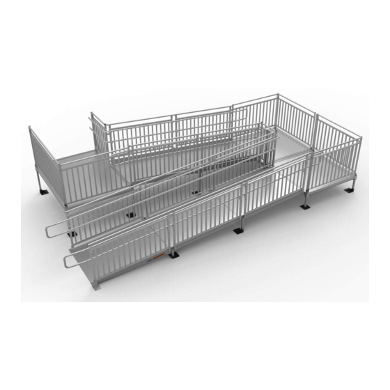
PATHWAY® HD
Code Compliant
Modular Access System
Image shown with multiple ramp and
platform rail options.
3-YEAR WARRANTY. Please register at www.ezaccess.com/warranty-satisfaction.
© EZ-ACCESS
®
, a division of Homecare Products, Inc. All rights reserved.
All text and images contained in this document are proprietary and may not be shared, modified, distributed,
reproduced, or reused without the express written permission of EZ-ACCESS.
Manufactured in the USA
17753 03-02-2020
Advertisement
Table of Contents

Subscribe to Our Youtube Channel
Related Manuals for EZ-ACCESS PATHWAY HD Code Compliant Modular Access System


Summary of Contents for EZ-ACCESS PATHWAY HD Code Compliant Modular Access System
- Page 1 , a division of Homecare Products, Inc. All rights reserved. All text and images contained in this document are proprietary and may not be shared, modified, distributed, reproduced, or reused without the express written permission of EZ-ACCESS. Manufactured in the USA...
- Page 2 To obtain replacement copies of instructions, warnings, and labels, call 1-800-451-1903. Professional installation, by an EZ-ACCESS approved technician, is required. This system is made from aluminum. Aluminum is electrically conductive. Do not lay power cords on or across electrically conductive materials, such as this system.
- Page 3 If any part of the system appears damaged, loose, or missing, do not use until repaired by an EZ ACCESS approved technician. Do not tamper with, attempt to repair, or modify any portion of the system. Only EZ-ACCESS approved technicians may provide service.
-
Page 4: Table Of Contents
RAMP SUPPORT ..............................82 PLATFORM EXTENDERS ..........................83-88 RAMP TRANSITION PLATE ..........................89 SINGLE BRIDGE PLATE ............................89 SECTION 8: MAINTENANCE PERIODIC MAINTENANCE ..........................90 SECTION 9: DEICING ..............................90 PATHWAY HD Code Compliant Modular Access System Installation Manual Page 4 of 92... -
Page 5: Section 1: Basic System Components
RAMPS AND RAMP HANDRAIL OPTIONS STARTER RAMP WITH TWO-LINE HANDRAILS* STARTER RAMP WITH PICKETED GUARDS* RAMP WITH TWO-LINE HANDRAIL RAMP WITH PICKETED GUARDS *END LOOPS SHOWN FOR CONTINUITY (ORDERED SEPARATELY) PATHWAY HD Code Compliant Modular Access System Installation Manual Page 5 of 92... - Page 6 PHDRHP – RAMP HANGER PAIR USED WHEN LEGS SUPPORT UPPER OR LOWER END OF RAMP ONLY TTP48, TTP54 & TTP60 – RAMP TRANSITION PLATE PHDHREP – HANDRAIL END PLUG PATHWAY HD Code Compliant Modular Access System Installation Manual Page 6 of 92...
- Page 7 PLATFORM EXTENDER WITH PICKETED TWO-LINE* END LOOPS END LOOPS SHOWN FOR SHOWN FOR CONTINUITY; CONTINUITY; ORDERED ORDERED SEPARATELY SEPARATELY *FEET & LEGS SHOWN FOR CONTINUITY (ORDERED SEPARATELY) PATHWAY HD Code Compliant Modular Access System Installation Manual Page 7 of 92...
- Page 8 • PHDXB36 USED ON 5’ XX DENOTES USABLE & 6’ PLATFORM LENGTH (LENGTHS SIDES & RAMPS AVAILABLE 10” PHDXB736 USED ON • THROUGH 112") 7’ PLATFORM SIDE PATHWAY HD Code Compliant Modular Access System Installation Manual Page 8 of 92...
- Page 9 PHDTBCG5, PHDTBCG6, PHDTBCG554, PHDTBCG654 TURN BACK CLOSURE TWO-LINE RAIL TURN BACK CLOSURE PICKETED GUARD PHDCTCTL5, PHDCTCTL6 PHDCTCG5, PHDCTCG6, PHDCTCG554, PHDCTCG654 CORNER TURN CLOSURE TWO-LINE RAIL CORNER TURN CLOSURE PICKETED GUARD PATHWAY HD Code Compliant Modular Access System Installation Manual Page 9 of 92...
-
Page 10: Section 2: Platforms
Platform in straight configuration Platform in turn configuration FIG. 2.3 Two platforms in turn back configuration (In a turn back configuration, connect any two platforms with equal length sides together) PATHWAY HD Code Compliant Modular Access System Installation Manual Page 10 of 92... -
Page 11: Install Support Legs And Feet And Adjust Platform Height
Place the platform with support legs attached into the upright position. Do not let the weight of the platform bear on the support legs while tipping the platform upright, as system damage and injury could result. PATHWAY HD Code Compliant Modular Access System Installation Manual Page 11 of 92... -
Page 12: Connect Two Platforms Together
2.3.7. Tighten the set screws in the platform corner pockets securely. 2.3.8. Adjust the platform heights and level as needed. 2.3.9. Tighten all setscrews securely. PATHWAY HD Code Compliant Modular Access System Installation Manual Page 12 of 92... - Page 13 FIG. 2.5 FIG. 2.6 PATHWAY HD Code Compliant Modular Access System Installation Manual Page 13 of 92...
-
Page 14: Install Cross Brace - Platforms
5/16”-18 x 1-1/2” long square neck carriage bolts, 5/16”-18 hex nuts, and 5/16” washers provided (FIG. 2.7). 2.4.9. Tighten all fasteners securely. PIVOT POINT (ALL X-BRACES) FIG. 2.7 PATHWAY HD Code Compliant Modular Access System Installation Manual Page 14 of 92... -
Page 15: Creating Decks From Platforms
(FIG. 2.8). 2.5.6. Tighten the inside set screws in corner pocket to hold the covers in place (FIG. 2.9). FIG. 2.8 INSIDE SET SCREW DETAIL FIG. 2.9 PATHWAY HD Code Compliant Modular Access System Installation Manual Page 15 of 92... -
Page 16: Section 3: Ramps
The starter ramp’s tapered section must be completely supported by the ground; do not use starter ramp in an elevated position (FIG. 3.3). FIG. 3.1 FIG 3.2 (BOTTOM VIEW) (BOTTOM VIEW) FIG. 3.3 PATHWAY HD Code Compliant Modular Access System Installation Manual Page 16 of 92... -
Page 17: Install Ramps On Platforms
(installed in a later step) is used. Do not attempt to walk on system until installation is complete. FIG. 3.4 FIG 3.5 (TOP VIEW) (BOTTOM VIEW) PATHWAY HD Code Compliant Modular Access System Installation Manual Page 17 of 92... -
Page 18: Attach Support Legs To Ramps
3.3.3. Level the support leg bracket, using a bubble level or similar tool, and then torque the two 5/16”-18 nylon insert locknuts to 20 ft.-lbs. (FIG. 3.7). FIG. 3.6 FIG. 3.7 PATHWAY HD Code Compliant Modular Access System Installation Manual Page 18 of 92... - Page 19 3.3.8. Insert a plug into the top of each support leg. Use a rubber mallet or similar tool to fully seat as needed. If necessary, use construction adhesive to bond the plug in place. FIG. 3.8 PATHWAY HD Code Compliant Modular Access System Installation Manual Page 19 of 92...
- Page 20 3.3.12. Ensure that all bolts and set screws are fully tightened as specified. 3.3.13. Ensure that the ramp sections are aligned parallel, on the same plane, to one another (FIG 3.10). FIG. 3.10 PATHWAY HD Code Compliant Modular Access System Installation Manual Page 20 of 92...
-
Page 21: Install Cross Brace - Ramps
5/16”-18 x 1-1/2” long square neck carriage bolts, 5/16” washers, and 5/16”-18 hex nuts provided (FIG. 3.11). 3.4.8. Tighten all fasteners securely. FIG. 3.11 PATHWAY HD Code Compliant Modular Access System Installation Manual Page 21 of 92... -
Page 22: Install A Single Ramp Or Ramp Run To An Existing Structure
Other types of anchoring devices may work in specific situations; contact your local contractor for assistance. FIG. 3.12 PATHWAY HD Code Compliant Modular Access System Installation Manual Page 22 of 92... -
Page 23: Angle Ramps With Respect To Landings
3.7.3. Anchor the transition plate as described in ‘ANCHOR RAMP TRANSITION PLATE’ section. ATHWAY 3.7.4. Use the 1/4″ x 1” long self-drilling screw when attaching to a P platform. FIG. 3.13 PATHWAY HD Code Compliant Modular Access System Installation Manual Page 23 of 92... -
Page 24: Section 4: Handrails
(do not fully tighten) until all handrails/guards have been installed on the ramp and/or platform. 4.1.3.6. Repeat for the remaining frames in the run. 4.1.3.7. Tighten all the fasteners securely. PATHWAY HD Code Compliant Modular Access System Installation Manual Page 24 of 92... - Page 25 FIG. 4.1 FIG. 4.2 PATHWAY HD Code Compliant Modular Access System Installation Manual Page 25 of 92...
-
Page 26: Starter Frame
4.3.5. The procedure for ramp handrail installation is the same for the starter ramp as other standard ramps; see ‘RAMP HANDRAILS’ section. PATHWAY HD Code Compliant Modular Access System Installation Manual Page 26 of 92... - Page 27 LOWER FRAME POST SUPPORT (RIGHT HAND SHOWN; LEFT HAND OPPOSITE) FIG. 4.3 FIG. 4.4 PATHWAY HD Code Compliant Modular Access System Installation Manual Page 27 of 92...
-
Page 28: Ramp Handrails
4.4.4.3. If a lower (child) handrail (purchased separately) is being used, install adjustable handrail bracket bottoms in the lower holes in the same manner. FIG. 4.5 PATHWAY HD Code Compliant Modular Access System Installation Manual Page 28 of 92... - Page 29 Tighten all the fasteners securely. 4.4.4.10. Repeat the process for all ramp handrail runs in the system, including the lower (child) handrails, if present. FIG. 4.6 FIG. 4.7 PATHWAY HD Code Compliant Modular Access System Installation Manual Page 29 of 92...
-
Page 30: Convert Two-Line Ramp Rails To Picketed Guards
4.5.3. Install the picketed guard on the ramp and connect the ramp handrails per the ‘RAMP HANDRAILS’ section. FIG. 4.8 PATHWAY HD Code Compliant Modular Access System Installation Manual Page 30 of 92... -
Page 31: Assemble Two-Line Platform Rails And Picketed Guards
5/16”-18 square threaded inserts in the barrier and mid rail (FIG. 4.9). Assemble both platform angle posts in the same manner. FIG. 4.9 PATHWAY HD Code Compliant Modular Access System Installation Manual Page 31 of 92... - Page 32 5/16” flat washer (use flat washer for the upper rail only; do not use a washer on the lowermost holes), the platform angle post, and into the 5/16”-18 square threaded inserts in the picketed guard (FIG. 4.10). FIG. 4.10 PATHWAY HD Code Compliant Modular Access System Installation Manual Page 32 of 92...
-
Page 33: Install Two-Line Platform Rails And Picketed Guards
(FIG. 4.12). 4.7.5.1. Securely tighten the 3/8”-16 headless socket set screws on the inside of the platform and below the platform deck. FIG. 4.11 PATHWAY HD Code Compliant Modular Access System Installation Manual Page 33 of 92... -
Page 34: Convert Two-Line Platform Handrails To Picketed Guards
4.8.3. Install the picketed guard in the same manner described in ‘ASSEMBLE TWO-LINE PLATFORM RAILS AND PICKETED GUARDS’ section. 4.8.4. Repeat for all sections requiring conversion. PATHWAY HD Code Compliant Modular Access System Installation Manual Page 34 of 92... -
Page 35: Section 5: Closures
Align the bottom of the post with the bottom of the corner pocket (FIG. 5.1). 5.1.3. Tighten the set screws securely. 5.1.4. Refer to ‘HANDRAILS’ section for additional details on securing the post. FIG. 5.1 PATHWAY HD Code Compliant Modular Access System Installation Manual Page 35 of 92... -
Page 36: Two-Line Rail Barrier And Mid Rail
Note the orientation of the larger 3/8” diameter hole with respect to the 1-1/2” x 2” section of the plate as shown (FIG. 5.3) to identify the barrier attachment plate needed. FIG. 5.2 FIG. 5.3 PATHWAY HD Code Compliant Modular Access System Installation Manual Page 36 of 92... - Page 37 1/4”-20 nylon insert locknuts, and 1/4” flat washers. Orient the head of the carriage bolt on the ramp side as shown (FIG. 5.5). 5.2.9. Tighten all fasteners securely. FIG. 5.4 FIG. 5.5 PATHWAY HD Code Compliant Modular Access System Installation Manual Page 37 of 92...
- Page 38 5.2.13. Cut the 1.5” x 2” closure mid rail to the measured length less 1/8” to account for the threaded inserts which will be installed after cutting. 5.2.14. Using a metal file, remove any sharp edges from cutting. FIG. 5.6 FIG. 5.7 PATHWAY HD Code Compliant Modular Access System Installation Manual Page 38 of 92...
- Page 39 Use the hole approximately in the middle of the platform angle post as shown (FIG. 5.8). 5.2.17. Tighten all fasteners securely. FIG. 5.8 PATHWAY HD Code Compliant Modular Access System Installation Manual Page 39 of 92...
-
Page 40: Two-Line Rail Top Rail
5.3.3. Tighten only enough to hold the elbow in place. 5.3.4. Insert a 2-15/16” ring joiner in the opposite end of the adjustable elbow with threaded insert (FIGs. 5.9 and 5.10). FIG. 5.9 FIG. 5.10 PATHWAY HD Code Compliant Modular Access System Installation Manual Page 40 of 92... - Page 41 (FIG. 5.12). 5.3.11. Tighten the adjustable elbow assembly screws and all 2-15/16” ring joiner set screws securely. FIG. 5.11 FIG. 5.12 PATHWAY HD Code Compliant Modular Access System Installation Manual Page 41 of 92...
-
Page 42: Picketed Guard Closure
Picketed guard closures are symmetric so can be installed with either rail on top. What becomes the “upper” or “lower” rail depends on how the closure is positioned at installation. FIG. 5.13 PATHWAY HD Code Compliant Modular Access System Installation Manual Page 42 of 92... - Page 43 5.4.6. Drill holes in the ramp side rail and attach the barrier attachment plate to the side rail in the same manner described in ‘CLOSURES’ section and shown (refer back to FIG. 5.5). FIG. 5.14 PATHWAY HD Code Compliant Modular Access System Installation Manual Page 43 of 92...
- Page 44 5.4.10. Attach the long leg of closure bracket to the closure post with a 5/16″-18 x 2-1/4″ hex bolt, 5/16” flat washers, and 5/16″-18 nylon insert locknut oriented as shown (FIG. 5.15). 5.4.11. Tighten all fasteners securely. FIG. 5.15 PATHWAY HD Code Compliant Modular Access System Installation Manual Page 44 of 92...
- Page 45 If necessary, use construction adhesive to bond the plug in place. 5.4.19. Tighten all fasteners securely. FIG. 5.16 PATHWAY HD Code Compliant Modular Access System Installation Manual Page 45 of 92...
-
Page 46: Closure Handrails
5.5.2. Level the tube bend with respect to the platform deck, and then tighten the joiner set screw to hold the tube bend in place (FIG. 5.17). FIG. 5.17 PATHWAY HD Code Compliant Modular Access System Installation Manual Page 46 of 92... - Page 47 5.5.8. Insert a 1-1/2” end plug into the open end of the tube bend (FIGs. 5.18 and 5.19). Use a rubber mallet or similar tool to fully seat as needed. 5.5.9. Tighten all fasteners securely. FIG. 5.18 FIG. 5.19 PATHWAY HD Code Compliant Modular Access System Installation Manual Page 47 of 92...
-
Page 48: Two-Line Rail Turn Back Closure
5.6.2. Tighten the set screws in the corner pocket to hold the covers in place (refer back to FIG. 2.9 for additional details on set screw locations). FIG. 5.20 PATHWAY HD Code Compliant Modular Access System Installation Manual Page 48 of 92... - Page 49 (refer back to FIG. 5.3) to identify which barrier attachment plate is needed. 5.6.6. Align the barrier attachment plates with sides of the barrier and tighten fasteners securely (FIG. 5.21). FIG. 5.21 PATHWAY HD Code Compliant Modular Access System Installation Manual Page 49 of 92...
- Page 50 5.6.11. Using a metal file, remove all sharp edges from cutting. FIG. 5.22 PATHWAY HD Code Compliant Modular Access System Installation Manual Page 50 of 92...
- Page 51 Orient the plate such that the mid rail is centered on both sides, and then tighten screws securely (FIG. 5.24). FIG. 5.23 FIG. 5.24 PATHWAY HD Code Compliant Modular Access System Installation Manual Page 51 of 92...
- Page 52 5.6.15. Connect the ramp handrails at the turn back by first inserting 2-15/16” ring joiners in the open ends of the ramp handrails and adjustable elbows on the opposite end of the ring joiner. FIG. 5.25 PATHWAY HD Code Compliant Modular Access System Installation Manual Page 52 of 92...
- Page 53 Remove and reinstall the adjustable elbows, if needed (FIG. 5.27). 5.6.21. Securely tighten adjustable elbow assembly screws and all ring joiner set screws. FIG. 5.26 FIG. 5.27 PATHWAY HD Code Compliant Modular Access System Installation Manual Page 53 of 92...
-
Page 54: Picketed Guard Turn Back Closure
Picketed guard closures are symmetric so can be installed with either rail on top. What becomes the “upper” or “lower” rail depends on how the closure is positioned at installation. FIG. 5.28 FIG. 5.29 PATHWAY HD Code Compliant Modular Access System Installation Manual Page 54 of 92... - Page 55 ‘PICKETED GUARD CLOSURE’ section except that the spacer between the closure posts and the barrier attachment plates is not used. FIG. 5.30 shows the components installed. FIG. 5.30 PATHWAY HD Code Compliant Modular Access System Installation Manual Page 55 of 92...
- Page 56 5.7.6. Insert 1-1/2” round threaded inserts into both ends of the 1-1/2” diameter tube. Use a rubber mallet or similar tool to fully seat as needed. (FIG. 5.31). FIG. 5.31 PATHWAY HD Code Compliant Modular Access System Installation Manual Page 56 of 92...
- Page 57 Install a 1-1/2” diameter tube bend on the opposite end of the joiner. Orient the joiner set screws toward the underside of the ramp handrails (FIG. 5.33). FIG. 5.32 FIG. 5.33 PATHWAY HD Code Compliant Modular Access System Installation Manual Page 57 of 92...
- Page 58 Use the holes in the handrail brackets welded to the turn back handrail as a template to drill 5/16” or 11/32” holes through the turn back angle posts. FIG. 5.34 PATHWAY HD Code Compliant Modular Access System Installation Manual Page 58 of 92...
- Page 59 5/16”-18 nylon insert locknuts, and 5/16” flat washers oriented as shown (FIG. 5.35). 5.7.23. Tighten all fasteners securely, including the ring joiner set screws if not tightened previously. FIG. 5.35 PATHWAY HD Code Compliant Modular Access System Installation Manual Page 59 of 92...
-
Page 60: Two-Line Rail Corner Turn
Refer to ‘TWO-LINE RAIL BARRIER AND MID RAIL’ section and complete the steps described to connect both frames to the platform angle post in the corner. FIG. 5.36 shows this stage of the assembly. FIG. 5.36 PATHWAY HD Code Compliant Modular Access System Installation Manual Page 60 of 92... - Page 61 5.8.7. Install the 1-1/2” diameter 90° elbow between the joiners. Remove and reinstall the adjustable elbows and ring joiners as needed. 5.8.8. Tighten all joiner set screws and elbow assembly screws securely. FIG. 5.37 FIG. 5.38 PATHWAY HD Code Compliant Modular Access System Installation Manual Page 61 of 92...
- Page 62 (FIG. 5.40). 5.8.12. Tighten all fasteners securely, including all ring joiner set screws and elbow assembly screws, if not completed previously. FIG. 5.39 FIG. 5.40 PATHWAY HD Code Compliant Modular Access System Installation Manual Page 62 of 92...
- Page 63 90° elbows toward platform angle post in the corner, and then tighten the joiner set screws enough to hold the elbows in place (FIG. 5.41). FIG. 5.41 PATHWAY HD Code Compliant Modular Access System Installation Manual Page 63 of 92...
- Page 64 (FIG. 5.42). 5.8.18. Using a metal file, remove any sharp edges from cutting. FIG. 5.42 PATHWAY HD Code Compliant Modular Access System Installation Manual Page 64 of 92...
- Page 65 Put pressure on the elbow until the threads engage and pull the components together (FIG. 5.43). 5.8.23. Tighten all fasteners securely including all ring joiner set screws and elbow assembly screws if not completed previously. FIG. 5.43 PATHWAY HD Code Compliant Modular Access System Installation Manual Page 65 of 92...
-
Page 66: Picketed Guard Corner Turn
Refer to ‘CLOSURES’ section and complete the steps described to assemble the handrails. FIG. 5.45 shows the completed guarded corner turn installation. FIG. 5.44 FIG. 5.45 PATHWAY HD Code Compliant Modular Access System Installation Manual Page 66 of 92... -
Page 67: Corner Turn Closure 54-In Wide Ramp On 5-Ft X 5-Ft Platform
5.10.3. Attach the legs of the angle post corner support brackets with the hole to the ramp frame posts using a 5/16”-18 x 1-1/4” long self-drilling, self-tapping hex washer head screws (FIG. 5.46). FIG. 5.46 PATHWAY HD Code Compliant Modular Access System Installation Manual Page 67 of 92... - Page 68 5.10.9. Tighten all fasteners securely, including all ring FIG. 5.48 joiner set screws and elbow assembly screws if not completed previously. PATHWAY HD Code Compliant Modular Access System Installation Manual Page 68 of 92...
-
Page 69: 5-Ft Wide Resting Platform
If necessary, use construction adhesive to bond the plug in place. 5.11.3. Repeat the procedure for all four corners of the platform. 5.11.4. Tighten all fasteners securely. FIG. 5.49 PATHWAY HD Code Compliant Modular Access System Installation Manual Page 69 of 92... - Page 70 5/16” flat washer removed from the guard or a 5/16”-18 x 2-1/4” hex bolt, 5/16”-18 locknut, and 5/16” flat washers if installing a two-line rail (FIG. 5.50). FIG. 5.50 PATHWAY HD Code Compliant Modular Access System Installation Manual Page 70 of 92...
- Page 71 (FIG. 5.51 or FIG. 5.50). 5.11.9. Repeat the procedure for all four corners of the platform. 5.11.10. Tighten all fasteners securely. FIG. 5.51 PATHWAY HD Code Compliant Modular Access System Installation Manual Page 71 of 92...
-
Page 72: Three Platform Deck Corner Closure
(FIG. 5.52) and secure in place in the same manner as described in ‘ASSEMBLE TWO-LINE PLATFORM RAILS AND PICKETED GUARDS’ section. FIG. 5.52 PATHWAY HD Code Compliant Modular Access System Installation Manual Page 72 of 92... - Page 73 5.12.5. Complete the installation of all handrail components (if required for your installation) and ‘FINAL PLATFORM/RAMP STEPS AND CHECKS’ section. FIG. 5.53 FIG. 5.54 PATHWAY HD Code Compliant Modular Access System Installation Manual Page 73 of 92...
-
Page 74: Section 6: Final Platform/Ramp Steps And Checks
(FIG. 6.1). Use an existing hole in the platform angle post if possible or field- drill a new 11/32” or 3/8” hole. 6.1.5. Tighten all fasteners securely. FIG. 6.1 PATHWAY HD Code Compliant Modular Access System Installation Manual Page 74 of 92... -
Page 75: Secure Ramps To Platforms
6.2.5. FIG. 6.4 shows the top view of the completed end clip installation. 6.2.6. Repeat this process for all locations where a ramp meets a platform. FIG. 6.2 FIG. 6.3 FIG. 6.4 PATHWAY HD Code Compliant Modular Access System Installation Manual Page 75 of 92... -
Page 76: Install Ramp Handrail End Loops
(FIG. 6.7). 6.3.2.4. Tighten the hex bolt securely. FIG. 6.5 FIG. 6.6 FIG. 6.7 PATHWAY HD Code Compliant Modular Access System Installation Manual Page 76 of 92... -
Page 77: Install Ramp Handrail End Loops With Lower (Child) Handrails
Referencing FIG. 6.9, note how the ends of the upper end loop angle downward and ends of the lower end loop angle upward. FIG. 6.9 PATHWAY HD Code Compliant Modular Access System Installation Manual Page 77 of 92... - Page 78 6.4.2.7. Drill pilot holes and install two 1/4” x 1” long self-drilling, self-tapping pan head Phillips screws in the upper handrail in the same manner described in step 6.3.2.5. FIG. 6.10 PATHWAY HD Code Compliant Modular Access System Installation Manual Page 78 of 92...
-
Page 79: Install Frame Top Rail End Plugs And Ramp Corner Protectors
6.6.1. As needed, use sandpaper (180 grit or equivalent) for blending scratches on handrails. Sand in direction of the grain as shown (FIG. 6.13). Do not use on painted or powder coated surfaces. FIG. 6.11 FIG. 6.13 FIG. 6.12 PATHWAY HD Code Compliant Modular Access System Installation Manual Page 79 of 92... -
Page 80: Final Checks
1.315” x 12” long stub tube to the 4” x 4” x 1/4” mounting base (FIG. 7.1). FIG. 7.1 PATHWAY HD Code Compliant Modular Access System Installation Manual Page 80 of 92... - Page 81 (FIG. 7.3). FIG. 7.2 1/4” X 1” LONG SELF-DRILLING, SELF-TAPPING PAN HEAD PHILLIPS SCREW FIG. 7.3 PATHWAY HD Code Compliant Modular Access System Installation Manual Page 81 of 92...
-
Page 82: Ramp Support
7.2.1.5. Refer to ‘ANCHOR RAMP TRANSITION PLATE’ section for anchoring ramp transition plate. FIG. 7.4 FIG. 7.5 PATHWAY HD Code Compliant Modular Access System Installation Manual Page 82 of 92... -
Page 83: Platform Extenders
7.3.4.2. Refer to ‘HANDRAIL CLOSURES’ section for installing a two-line rail closure or picketed guard closure. FIG. 7.6 PATHWAY HD Code Compliant Modular Access System Installation Manual Page 83 of 92... - Page 84 5/16” flat washers with a 2” x 4-1/8” tie strap between the flat washer and 1-1/2” square x 42-7/16” long closure post, oriented toward the platform extender at the 1-1/2” x 2” barrier (FIG. 7.7). FIG. 7.7 PATHWAY HD Code Compliant Modular Access System Installation Manual Page 84 of 92...
- Page 85 5/16”-18 x 1” long hex bolts, 5/16”-18 locknuts, and 5/16” flat washers oriented as shown. 7.3.4.9. Tighten all fasteners securely. FIG. 7.8 FIG. 7.9 PATHWAY HD Code Compliant Modular Access System Installation Manual Page 85 of 92...
- Page 86 5/16”-18 x 1” long hex bolts, 5/16”-18 locknuts, and 5/16” flat washers oriented as shown (FIG. 7.12). 7.3.4.5. Tighten all fasteners securely. FIG. 7.10 FIG. 7.11 FIG. 7.12 PATHWAY HD Code Compliant Modular Access System Installation Manual Page 86 of 92...
- Page 87 1” to 2” from platform corner pocket. 7.3.4.8. Attach using the four 1/4” x 1” long self-drilling, self-tapping pan head Phillips screws provided (FIG. 7.13). FIG. 7.13 PATHWAY HD Code Compliant Modular Access System Installation Manual Page 87 of 92...
- Page 88 7.3.4.10. Complete all remaining steps in ‘FINAL PLATFORM/RAMP STEPS AND CHECKS’ section as required for the installation. FIG. 7.14 PATHWAY HD Code Compliant Modular Access System Installation Manual Page 88 of 92...
-
Page 89: Ramp Transition Plate
Ensure that at least 1” on each of the supporting edges of the single bridge plate is supported on a level, sound surface that is free from defects and can support the same structural loads as the system (FIG 7.16). FIG. 7.16 PATHWAY HD Code Compliant Modular Access System Installation Manual Page 89 of 92... -
Page 90: Section 8: Maintenance
For the safety of all users, it is important to keep your system clear of snow, ice, and other debris. Always follow the deicing agent manufacturer’s directions. EZ-ACCESS® will not be held responsible for any injuries or damages that arise from the information provided. ALWAYS check with the deicing product’s manufacturer or your local supplier to determine which method is best for your situation. - Page 92 Thank you for choosing EZ-ACCESS ® for your accessibility needs. www.ezaccess.com...
Need help?
Do you have a question about the PATHWAY HD Code Compliant Modular Access System and is the answer not in the manual?
Questions and answers