Advertisement
Quick Links
PASSPORT® Vertical Platform Lift (VPL)
Installation Supplement for
120" (10'), 144" (12'), and 168" (14')
Models: PL120SP3651, PL120TP3860, PL144SP3651, PL144TP3860, PL168SP3651, & PL168TP3860
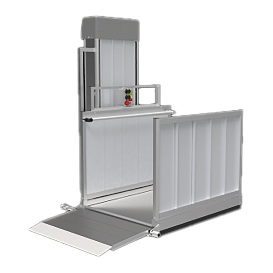
Image shown is a 14' PASSPORT®
Vertical Platform Lift with Straight
Platform and 2 Back Braces.
Manufactured in the USA
2-YEAR WARRANTY. Please register at www.ezaccess.com/warranty-satisfaction.
© EZ-ACCESS
All text and images contained in this document are proprietary and may not be shared, modified,
distributed, reproduced, or reused without the express written permission of EZ-ACCESS.
®
, a division of Homecare Products, Inc. All rights reserved.
18798 REV 06-27-19
Advertisement

Related Manuals for EZ-ACCESS PASSPORT PL120SP3651


Summary of Contents for EZ-ACCESS PASSPORT PL120SP3651
- Page 1 , a division of Homecare Products, Inc. All rights reserved. All text and images contained in this document are proprietary and may not be shared, modified, distributed, reproduced, or reused without the express written permission of EZ-ACCESS. Manufactured in the USA...
- Page 2 TABLE OF CONTENTS Section 1 .......... UNCRATING THE VPL Section 2 .......... GUARD RAMP ACTIVATING BAR Section 3 .......... INSTALLING AND CONNECTING BATTERIES Section 4 .......... LIFTING THE VPL Section 5 .......... INSTALLING BACK AND SIDE BRACING Section 6 .......... REMOVE REMAINING SHIPPING MATERIALS Section 7 ..........
- Page 3 Read the and understand the Installation Manual and all Supplements and Addendums in their entirety. Understand and learn the location and function of all the features, weight capacity, safety devices, and labels before operating any PASSPORT Vertical Platform Lift. Determine which side the guard ramp will be attached to and verify adequate clearances. Platform must travel up and down and guard ramp must fold and unfold without interference or obstruction.
-
Page 4: Required Tools
VPL must be anchored to a concrete slab and braced to a proper structure before operating the VPL while it is occupied. Maintaining all labels and manuals in legible condition is required by the VPL owner and is essential for safe VPL operation. - Page 5 UNCRATING 1.1 Remove banding from Platform Box and Gate Box (if included) and remove from pallet (FIG. 1.1) and set aside 1.2 Before continuing, see FIGs. 1.1, 1.2, and 1.3. Remove, open, and read installation instructions. 1.3 From inside the VPL tower remove the following and set aside: 1.3.1 4 Tower Panels (panels are labeled on back with blue tape;...
- Page 6 FIG. 1.2 FIG. 1.3 Page | 6...
- Page 7 GUARD RAMP ACTIVATING BAR If you wish to install the Guard Ramp Activating Bar before lifting the VPL into place, go to step 2.1. Otherwise, refer to the PASSPORT® Vertical Platform Lift (VPL) Installation Manual for Guard Ramp Activating Bar installation information. The Guard Ramp Activating Bar must always be installed on the same side as the guard ramp.
-
Page 8: Installing And Connecting Batteries
INSTALLING AND CONNECTING BATTERIES Before continuing, confirm the keyed switch is in the ‘off’ position and that the emergency stop switch is pushed in. 3.1. INSTALLING BATTERIES 3.1.1. Remove batteries from shipping box and set in place on power head mounting plate to determine installation location. - Page 9 FIG. 3.2 FIG. 3.3 FIG. 3.4 Page | 9...
- Page 10 3.2. CONNECTING BATTERIES Confirm battery polarities before connecting wires. 3.2.1. Near the power head, locate the small blue polybag. Remove the zip-tie and then remove the wires from the polybag bag (FIG. 3.5). 3.2.2. Connect the White #10AWG wire to the Negative terminal of Battery 1 (FIG. 3.5). 3.2.3.
- Page 11 LIFTING THE VPL Do not lift VPL from pallet if you do not have bracing to secure VPL to vertical structure. Do not attempt to lift VPL from pallet until all shipping lag bolts and zip ties have been removed. 4.1.
- Page 12 INSTALLING BACK AND SIDE BRACING Install bracing after properly anchoring VPL to concrete pad. Bracing is required for 10’, 12’, and 14’ VPLs. Standard bracing is available in 2 configurations; back brace and side brace. See TABLE 1, FIG. 5.1, and FIG 5.2 for available of bracing. If you are supplying your own bracing, professional design and installation is required.
- Page 13 5.1. ATTACHMENT Hardware for attaching bracing to vertical structures is supplied by others. See Technical Specifications for detailed side and back bracing dimensional information. 5.1.1. BACK BRACE 5.1.1.1. Back Brace Wall Mount Attachment Detail, used when mounting the VPL to a vertical structure to the rear of the VPL, is shown in FIG.
- Page 14 10’ VPL WITH BACK BRACE ADJUSTMENT RANGE: WALL OR STRUCTURE 10” TO 24” BEHIND VPL FIG. 5.4 FIG. 5.5 (DETAIL A SHOWN) FIG. 5.6 (DETAIL B SHOWN) Page | 14...
- Page 15 5.1.2. SIDE BRACE 5.1.2.1. Side Brace Wall Mount Attachment Detail, used when mounting the VPL to a vertical structure to one side or the other of the VPL, is shown in FIG. 5.7. 5.1.2.2. Once you have confirmed bracing is undamaged, set bracing in place and hold with clamps, ensuring a dimensionally and structurally sound fit between VPL and vertical structure.
- Page 16 10’ VPL WITH SIDE BRACE ADJUSTMENT RANGE: WALL OR STRUCTURE 0” TO 3” BEHIND VPL FIG. 5.8 FIG. 5.9 (DETAIL C SHOWN) FIG. 5.10 (DETAIL D SHOWN) Page | 16...
- Page 17 5.1.3. FIGs. 5.11 through 5.18 shown for assembled understanding. The 120” VPL uses 1 back or side brace. The 144” VPL and the 168” each require 2 braces, as shown on the 144” below, so the 168” is not shown. 120”...
- Page 18 CONTROL VOLTAGE SAFETY SERVICE SWITCH “HOOD SWITCH” 7.1. The VPL comes with a CONTROL VOLTAGE SAFETY SERVICE SWITCH (“hood switch”), a control voltage disconnect (“switch”) that is located under the power head cover (“hood”) as shown in FIG. 7.1. 7.2. This hood switch is a magnetic reed switch which works in conjunction with a magnet mounted to the inside of the hood on the angle.
- Page 19 INSTALLING PLATFORM GATE 8.1. VPLs taller than 72” include, as standard equipment, a Platform Gate (“gate”). 8.2. The gate is installed on the guard ramp side of the platform. Its tension hinges are adjustable and can mount left or right. 8.3.
- Page 20 FIG. 8.1 FIG. 8.2 Page | 20...
-
Page 21: Inspection And Testing
INSPECTION AND TESTING 9.1. Inspect all fasteners and ensure all fasteners and anchors are tightened securely. 9.2. Refer to your PASSPORT® Vertical Platform Lift (VPL) Installation Manual for additional information on testing VPL functions. TOWER PANELS Tower Panels (“panels”) must be handled with extreme caution and care; they can become dangerous if falling or sliding. -
Page 22: Final Testing
FRONT PANEL INSTALLATION FIG. 10.2 FINAL TESTING 11.1 Once all installation is complete, perform a final functional test. Refer to your PASSPORT® Vertical Platform Lift (VPL) Installation Manual for additional information on final testing procedures. 11.2 If you have any questions, please refer to your PASSPORT® Vertical Platform Lift (VPL) Installation Manual for additional information or call 1-800-451-1903.
Need help?
Do you have a question about the PASSPORT PL120SP3651 and is the answer not in the manual?
Questions and answers