Table of Contents
Advertisement
PASSPORT® Vertical Platform Lift (VPL)
Installation Manual
Models: PL44SP3651, PL44TP3860, PL52SP3651, PL52TP3860, PL72SP3651, & PL72TP3860
2-year Warranty. Please register at www.ezaccess.com/warranty-satisfaction.
®
© EZ-ACCESS
, a division of Homecare Products, Inc. All rights reserved.
Manufactured in the USA
All text and images contained in this document are proprietary and may not be shared, modified, distributed,
reproduced, or reused without the express written permission of EZ-ACCESS.
12274 11-22-19
Page | 1
Advertisement
Table of Contents

Related Manuals for EZ-ACCESS Passport PL44SP3651


Summary of Contents for EZ-ACCESS Passport PL44SP3651
- Page 1 , a division of Homecare Products, Inc. All rights reserved. Manufactured in the USA All text and images contained in this document are proprietary and may not be shared, modified, distributed, reproduced, or reused without the express written permission of EZ-ACCESS. 12274 11-22-19 Page | 1...
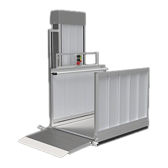
- Page 2 PL44SP3651 — 44” MAXIMUM HEIGHT PL44TP3860 — 44” MAXIMUM HEIGHT STRAIGHT PLATFORM TURN PLATFORM PL52SP3651 — 52” MAXIMUM HEIGHT PL52TP3860 — 52” MAXIMUM HEIGHT STRAIGHT PLATFORM TURN PLATFORM PL72SP3651 — 72” MAXIMUM HEIGHT PL72TP3860 — 72” MAXIMUM HEIGHT STRAIGHT PLATFORM TURN PLATFORM Page | 2...
-
Page 3: Table Of Contents
TABLE OF CONTENTS INTRODUCTION, IMPORTANT SHIPPING INFORMATION, REQUIRED TOOLS, TOOLS INSTALLERS MAY FIND USEFUL ......4 SYMBOLS, SAFETY, AND WARNINGS ..............................5 ATTENTION INSTALLER: PRIOR TO INSTALLATION ..........................5 WARNINGS ......................................6 SECTION 1: HARDWARE CONTENTS ..............................7 SECTION 2: LABELING .................................... 8 SECTION 3: OPTIONAL EQUIPMENT NOTICE ............................ -
Page 4: Introduction, Important Shipping Information, Required Tools, Tools Installers May Find Useful
INTRODUCTION This manual covers installation for the 44”, 52”, and 72” heights of the PASSPORT® Vertical Platform Lift. Throughout this document, the PASSPORT Vertical Platform Lift is also referred to as “VPL” or “Lift”. Before using the VPL, read and understand this manual as well as the User Manual, Supplements (including the PASSPORT®... -
Page 5: Symbols, Safety, And Warnings
The symbol may appear in various colors and in conjunction with other symbols. PRIOR TO INSTALLATION Professional installation by an EZ-ACCESS approved technician is required. Anchoring and bracing drawing details, if required, are the responsibility of the installer. -
Page 6: Warnings
Contact your dealer to schedule any needed inspections, repairs, or service. Do not tamper with, attempt to repair, or modify any portion of the VPL. Only EZ-ACCESS approved technicians may service the VPL. Contact your dealer to schedule inspections, repairs, or service. -
Page 7: Section 1: Hardware Contents
HARDWARE CONTENTS STRAIGHT PLATFORM TURN PLATFORM IMAGE* DESRIPTION IMAGE* DESCRIPTION GUARD RAMP PIVOT PLATE WELDED PIVOT PLATE ASSEMBLY PIVOT PLATE BOLT GUARD RAMP PIVOT PLATE 1.4”-20 X ½” LONG HEX BOLT GUARD RAMP SPACER PIVOT PLATE BOLT 2” O.D. X 11/16” LONG 1.4”-20 X ½”... -
Page 8: Section 2: Labeling
LABELING 2.1. Maintaining all labels and manuals in legible condition is required by the VPL owner and is essential for safe operation. Labels are pre-installed and positioned as shown (FIG. 2.1). These labels may vary in color, border style, size, and written content. For replacement copies, please contact your dealer or call 1-800-451-1903. -
Page 9: Section 3: Optional Equipment Notice
OPTIONAL EQUIPMENT NOTICE 3.1. VPL options are sold separately. To order optional equipment, contact your dealer or call 1-800-451-1903 for additional information. CONTROL VOLTAGE SAFETY SERVICE SWITCH “HOOD SWITCH” 4.1. For lifts taller than 72”, refer to the PASSPORT® Vertical Platform Lift (VPL) Installation Supplement for 120” (10’), 144”... -
Page 10: Section 5: Assembling The Vpl
ASSEMBLING THE VPL It is assumed at this stage that you have already poured a reinforced concrete pad for anchoring your VPL. 5.1. Assemble the VPL a few inches away from its final position, and carefully reposition as required. VPLs are top heavy; use extreme caution when moving VPLs. 5.2. - Page 11 5.8. STRAIGHT PLATFORM 5.8.1. Lift the platform assembly onto carriage, engaging both 1½” square tubes on the platform to the corresponding hooks in the carriage. Never lift or carry the platform using the safety pan. Damage to the safety pan sensors can occur rendering the lift unsafe or inoperable.
- Page 12 5.8.3. Locate the wiring connector protruding from the back of the platform and attach to the corresponding connector on carriage (FIG. 5.3). If installing a Turn Platform, connect the platform plug, and then skip to Step 5.10. FIG. 5.3 5.8.4. Install 5/16”-18 x 2” ss button head screw on pivot plate. Secure with 5/16”-18 locknut (FIG. 5.4). This screw must be installed to prevent the guard ramp from contacting the guard wall.
- Page 13 5.8.8. Locate the 5/16”-18 x 2” hex bolt and locknut before installing the pivot arm assembly (FIG. 5.4 and FIG. 5.5). 5.8.9. Slide the pivot arm into the torque tube on the guard ramp until the bolt hole in the torque tube aligns with the hole in the pivot arm.
- Page 14 5.8.12. Install the guard walls with the smooth side toward inside of the platform (FIG. 5.6). Loosen two set screws in each platform corner pocket as needed to fully engage the guard wall posts. Tighten all set screws securely after the guard walls are installed. Ensure guard wall with two holes in top rail is installed closest to the tower (FIG.
- Page 15 5.8.13. Install control box mounting frame to rear guard wall by first removing nuts and bolts from control box mounting frame posts (FIG. 5.7). Installation of the control box mounting frame is the same for the turn platform and the straight platform. 5.8.14.
- Page 16 FIG. 5.8 5.8.15. The control box (FIG. 5.8) is secured to inside of tower with zip ties. Locate and cut the zip ties to free the control box. 5.8.16. Remove fasteners securing mounting channels to control box. 5.8.17. Position control box into the mounting frame as shown (FIG 5.8) and reinstall the mounting channels using the fasteners removed in the previous step.
- Page 17 5.9. TURN PLATFORM 5.9.1. When assembling a turn platform, one pivot plate is installed on the side closest to the lift tower and one welded pivot plate assembly is installed in the opposite corner. 5.9.2. Determine which end of the platform the guard ramp will be installed on. 5.9.3.
- Page 18 5.9.8. Install the rear guard wall with the smooth side toward the inside of platform (FIG. 5.11). 5.9.9. Loosen the two set screws in each of the platform corner pockets (closest to the lift tower) as needed to fully engage the guard wall posts. Tighten all set screws securely after the guard wall is installed.
- Page 19 5.9.10. Install the side guard wall with the smooth side toward the inside of platform (FIG. 5.12). The side guard wall comes with its post installed on one side. If the post is not on the side needed for the smooth side to be installed toward the inside of the platform, disassemble the post from the guard wall and reinstall on the opposite side before proceeding.
-
Page 20: Section 6: Confirm Basic Vpl Operation
CONFIRM BASIC VPL OPERATION If plugged in to an AC outlet, unplug the VPL 120-volt AC power cord before proceeding with next steps. Do not operate a VPL that has not been properly anchored to the reinforced concrete pad. If cover panels are not installed, the VPL’s internal mechanisms will be exposed at this point. Be sure to keep all body parts and loose clothing, as well as other people and pets, clear of the VPL to avoid injury. -
Page 21: Section 7: Placement And Installation
PLACEMENT AND INSTALLATION 7.1. If using VPL with the optional Top Landing Gate, proceed to SECTION 9 prior to placing and installing VPL. 7.2. Position the VPL in its approximate final position. 7.3. Plug VPL into AC power, reinsert key into the keyed power switch, and turn to the ‘Power On’ position. 7.4. - Page 22 7.12. Locate the limit switch trigger on the upper right inside of the tower side. Place a mark on the tower side aligned with one of the flat head adjustment screws on the limit trigger (FIG. 7.2). 7.13. Measures down from the mark on the tower side by the same dimension recorded in the previous step and mark the tower at this point.
-
Page 23: Section 8: Optional Equipment - Wireless Remote
OPTIONAL EQUIPMENT – WIRELESS REMOTE 8.1. OVERVIEW 8.1.1. The wireless remote allows remote operation of the VPL from a suitable location and can be used in conjunction with the call/send control option. Multiple FOB transmitters allow VPL operation from various locations, for instance, inside a home or vehicle. Do not allow unauthorized persons to use the VPL or wireless remote. - Page 24 8.3.5. Illustration of overall installation of the receiver (FIG. 8.3). 8.3.6. To install the antenna, drop antenna cable down through the VPL’s tower wire channel (FIG. 8.4). 8.3.6.1. Note the location of the hook and loop fastener on the underside of the antenna (FIG.
- Page 25 8.3.7. Once the mount location for the antenna is determined, remove protective adhesive from hook and loop fastener and press to stick the antenna in place (FIG. 8.6). 8.3.8. Plug the antenna into the receiver (FIG. 8.7). 8.3.9. Stow excess antenna cable neatly and securely away from all VPL moving parts. 8.3.10.
-
Page 26: Section 9: Optional Equipment - Top Landing Gate
Use only recommended fasteners and attachment points for anchoring the top landing gate. Call your dealer for service if the top landing gate does not fully close unassisted and do not use until repairs have been completed by an EZ-ACCESS approved technician. 9.2. - Page 27 FIG. 9.1 FIG. 9.2 Page | 27...
- Page 28 9.4.5. Complete the remaining steps in SECTION 5. 9.4.6. Place the top landing gate on the porch or deck and adjust its position side to side until the front or rear guard wall of the platform aligns with the latch roller on the top landing gate without hitting the latch (FIG.
- Page 29 9.4.8. The top landing gate comes with four 1/4” self-drilling screws for attaching the top landing gate sill to the deck surface and two 5/16”-18 x 4-1/2” long hex bolts for attaching the top landing gate sill to the deck fascia (FIG. 9.4). 9.4.9.
- Page 30 FIG. 9.5 9.4.10. Before connecting the top landing gate cord, the VPL platform must be set at the upper landing level. Proceed with Steps 7.9 through 7.18 in SECTION 7 if not already complete. 9.4.11. Connect the top landing gate cord to VPL by first removing rear cover. There will be a cord with a 4-pin connector inside the tower located in the area where the power cord exits the tower.
- Page 31 FIG. 9.6 9.4.18. The top landing gate will come preassembled with approximately a 1/2” gap between the bottom of the top landing gate frame and the sill. If needed, the top landing gate can be adjusted up or down to accommodate field conditions. 9.4.18.1.
- Page 32 9.5. TOP LANDING GATE LATCH COVER 9.5.1. PRIOR TO INSTALLATION 9.5.1.1. The top landing gate latch cover (FIG. 9.6) is installed over the latch on the top landing gate (“gate”). Ensure that you have the properly handed (left or right) latch cover for the gate.
- Page 33 9.5.2. MODIFYING TOP LANDING GATE 9.5.2.1. Remove plastic ball cap from upper strike rod and discard; you will not reuse it. 9.5.2.2. Mark the upper strike rod 1-3/8” from the outside of the gate (FIG. 9.9). 9.5.2.3. Verify that the upper strike rod will clear the latch cover and engage with the latch when cut at the mark.
- Page 34 9.5.3. INSTALLATION OF GATE LATCH COVER 9.5.3.1. Remove gate post cap from latch post and set aside for later use (FIG. 9.10). 9.5.3.2. Attach mounting plate loosely to the back side of the latch cover with provided 5/16”-18 x 1/2” button head socket cap screw (FIG. 9.11). 9.5.3.2.1.
- Page 35 9.5.3.3. Put latch cover assembly in place by sliding the mounting plate into the same post channel as the existing gate latch mechanism mounting plate (FIG. 9.12). The cut-out on the back of the cover fits around the latch mechanism clamp plate.
-
Page 36: Section 10: Optional Equipment - Top Landing Gate Connector To Pathway Handrail
OPTIONAL EQUIPMENT – TOP LANDING GATE CONNECTOR TO PATHWAY HANDRAIL 10.1. INTRODUCTION 10.1.1. Connector kits are designed to fill the space between the VPL’s top landing gate (“gate”) and a two-line platform handrail post on a PATHWAY® Modular Access System. 10.1.2. - Page 37 10.2.5. Place the gate on the platform and use the upper mounting holes in the gate sill as a template to drill 5/16” or 11/32” holes through the platform side rail (FIG. 10.2). 10.2.6. Install the two 5/16”-18 x 4-1/2” long hex bolts through the sill and the platform side rail, then secure with lock nuts and washers (FIG.
- Page 38 10.2.15. Once the screw splines are aligned correctly, use two #10 x 1” long self-tapping hex washer head screws through the platform post to attach the open end of the handrail tube to the platform post and tighten the 5/16”-18 x 3/4” long button head socket clamp screws securely.
- Page 39 10.3. INSTALLATION TO PATHWAY® 3G 10.3.1. The PATHWAY® 3G connector kit, also known as a closure kit, includes two 1-1/2” diameter handrail tubes, two connector plates, two clamp plates, two 5/16”-18 threaded round tube inserts, and attachment hardware (FIG. 10.4). If connecting both gate posts to platform handrail posts, use two kits.
- Page 40 10.3.9. Tap a 5/16”-18 threaded round tube insert into the end of the 1-1/2” diameter tube, opposite the end you installed the connector plate on (FIG. 10.5). 10.3.10. Orient the connector plate as shown (FIG. 10.5) with the clamp plate below the handrail tube and toward the platform side of the gate post.
-
Page 41: Section 11: Optional Equipment - Top Landing Gate Connector To Wood Deck
OPTIONAL EQUIPMENT – TOP LANDING GATE CONNECTOR TO WOOD DECK 11.1. OVERVIEW 11.1.1. This option is used to tie the top landing gate post to handrails or posts on an existing wood porch or deck. Each connector includes two clamp plates, two angle connectors, and attachment hardware (FIG. - Page 42 11.1.2. Insert two 5/16”-18 x 3/4” long button head socket clamp screws through the slots in one leg of the angle connector and into the tapped holes in the clamp plate (FIG. 11.2). Do not fully tighten fully at this time. FIG.
-
Page 43: Section 12: Optional Equipment - Platform Safety Rail
OPTIONAL EQUIPMENT – PLATFORM SAFETY RAIL 12.1. OVERVIEW 12.1.1. The platform safety rail (FIG. 12.1) is designed exclusively for the purpose of providing additional personal stability while standing on the VPL. The platform safety rail is required for anyone who will be standing on the VPL. Do not install the platform safety rail on the outside of the platform guard walls;... - Page 44 12.3. INSTALLATION 12.3.1. STRAIGHT PLATFORM 12.3.1.1. Measure 3/4” in from the end of one guard wall post and make a mark. Next, measure 2-1/2” down from the top of the guard wall post (excluding the plug) and mark. Find the location where the two marks cross. Mark a location on the other guard wall post 2-1/2”...
- Page 45 12.3.3. Install a round threaded insert into one end of each 1-1/2” diameter x 1-1/4” long tube (FIG. 12.5). Use a rubber mallet to fully seat the threaded inserts into tubes. 12.3.4. Hold one 1-1/2” diameter x 1-1/4” long tube with the threaded insert to the inside of the guard wall (tube will be oriented toward the guard wall post or top rail and the insert will be oriented toward the other side of the platform).
- Page 46 12.3.6.4. After tightening, the rounded side of the elbow halves should be on the bottom facing the platform. It may be necessary to loosen the hex cap screws holding the round tubes with threaded inserts and rotate in one direction or the other. Re-tighten to get the elbows to end up in the correct orientation when fully secured (FIG.
-
Page 47: Section 13: Optional Equipment - Platform Safety Pan Weather Guard
OPTIONAL EQUIPMENT – PLATFORM SAFETY PAN WEATHER GUARD 13.1. The platform safety pan weather guard (“weather guard”) installs by clipping it onto the safety pan (FIG. 13.1). 13.2. Begin at the rear (closest to lift) and adjacent to one of the outer carriage arms (FIG. 13.2). Orient the weather guard with the flap pointing up toward the platform and firmly press onto the outer edge of the safety pan until fully engaged (FIG. -
Page 48: Section 14: Optional Equipment - Interlock
OPTIONAL EQUIPMENT – INTERLOCK 14.1. BEFORE YOU BEGIN 14.1.1. Read this section in its entirety before beginning the installation process. 14.1.2. For interlock installation, see the Porta Electric Door Lock (6-position) Installation Instructions, which came with your Porta Electric Door Lock. 14.1.3. - Page 49 14.2. INSTALLATION PREPARATION 14.2.1. Interlock electrical connections are shown in FIG. 14.5 and FIG. 14.6. 14.2.2. Strip the 18/4 SOOW cord insulation back, exposing approximately 1.25” of internal 4- white, black, green, and red wires (FIG. 14.5). 14.2.3. Strip the insulator from the internal white, black, green, and red wires to expose 1/2” of the conductor (FIG.
- Page 50 14.3. INSTALLATION 14.3.1. Turn VPL keyed power switch to ‘Power Off’ position, remove key, and unplug VPL from AC power. Failure to turn the VPL keyed power switch to the ‘Power Off‘ position, remove key, and unplug AC power cord could create a dangerous situation and result in equipment damage or failure, injury to property, risk of electrical shock, risk of fire, risk of crushing injuries, risk of serious personal injury, and or death.
- Page 51 14.3.11. Connect the male spade connector on the end of the 16” black wire with the 1/4” ring terminal on the opposite end to the female spade connector on the blue wire, which was disconnected in the previous step. (FIG. 14.14). 14.3.12.
-
Page 52: Section 15: Optional Equipment - Call/Send Control
OPTIONAL EQUIPMENT – CALL/SEND CONTROL 15.1. OVERVIEW 15.1.1. The call/send control allows you to “call” the VPL up or down (FIG. 15.1). Multiple call/send controls can be used, allowing the lift to be called from various locations (fig. 15.2). Press the ‘down’... - Page 53 15.2. INSTALLATION 15.2.1. Connect the call/send control cord to VPL by first removing rear cover panel. 15.2.2. Locate the cord with a 3-pin connector inside the tower (this cord is positioned in the area where the power cord exits the tower). 15.2.3.
-
Page 54: Section 16: Optional Equipment - Call/Send Control Mounting Kit
OPTIONAL EQUIPMENT – CALL/SEND CONTROL MOUNTING KIT 16.1. OVERVIEW 16.1.1. The call/send control mounting kit (FIG. 16.1) is used to mount the call/send control to the top landing gate post. The kit includes two mounting bars, one attachment bar, and attachment hardware. - Page 55 16.2.2. Assemble the two mounting bars to the call/send control using four #10-24 x 3/4” long button head socket cap screws and nylon locking nuts (FIG. 16.2). Assemble the bars in such a manner that the larger hole is on the gate side when mounted to the same post which contains the latching mechanism.
-
Page 56: Section 17: Optional Equipment - Turn Platform Pivot Post
OPTIONAL EQUIPMENT – TURN PLATFORM PIVOT POST 17.1. OVERVIEW 17.1.1. The turn platform pivot Post (FIG. 17.1) is used when a top landing gate latch is mounted opposite the guard wall (FIG. 17.1). This option replaces the welded pivot plate. 17.2. -
Page 57: Section 18: Optional Equipment - Platform Gate
OPTIONAL EQUIPMENT – PLATFORM GATE 18.1. OVERVIEW 18.1.1. VPLs taller than 72” include a platform gate as standard equipment. The platform gate is an option available for lifts 72” and shorter. 18.1.2. Installation is always on the guard ramp side of the platform. Its tension hinges are adjustable and can mount left or right. - Page 58 18.2.5. Hinge tension is factory set. However, tension can be adjusted as desired on both hinges using a flat screwdriver and adjusting from the top. Depress and turn counterclockwise to increase tension, clockwise to release tension. The platform gate should swing fully shut gently so as not to bounce off bumper (installed in next steps) more than once.
-
Page 59: Section 19: Maintenance And Service
MAINTENANCE AND SERVICE 19.1. OVERVIEW 19.1.1. Maintenance and service must be performed only by an EZ-ACCESS approved technician. Contact your dealer with questions or to schedule any needed inspections, repairs, or service. 19.1.2. If the platform and guard ramp surface are covered with frost, ice and or snow, remove frost, ice and or snow before using the VPL. -
Page 60: Section 20: Batteries
BATTERIES 20.1. BEFORE YOU BEGIN Before performing battery services, confirm the keyed power switch is in the ‘Power Off’ position and that the emergency stop switch is pushed in. 20.1.1. The VPL comes with two standard batteries, each are 12-volt 12 Ah valve regulated (VRLA) AGM, sealed lead acid batteries in spill proof housing. - Page 61 20.3. BATTERY INSTALLATION 20.3.1. Set replacement batteries in same orientation as the batteries previously removed. Field-replaced batteries do not use double-back foam tape or hook and loop fastener. 20.3.2. Insert bolt (removed earlier) through battery hold down, between batteries, and through power head mounting plate (FIG.
- Page 62 Before continuing, confirm the keyed switch is in the ‘Power Off’ position and that the emergency stop switch is pushed in. 20.3.5. Using FIG. 20.3 as a guide, plug previously removed wires back into batteries. 20.3.5.1. Connect the red #10AWG to the positive terminal of Battery 2. 20.3.5.2.
-
Page 63: Section 21: Hi-Lead Screw Lubrication
HI-LEAD® SCREW LUBRICATION 21.1. OVERVIEW 21.1.1. The Hi-Lead® Screw (“screw”) drives the lift platform up and down and must be lubricated at minimum once per year or more frequently if the VPL is used in extremely hot or cold locations (FIG. 21.1). 21.1.1.1. -
Page 64: Section 22: Anchoring Vpl To Reinforced Concrete Pad
ANCHORING VPL TO REINFORCED CONCRETE PAD 22.1. OVERVIEW 22.1.1. The VPL must be anchored “plumb”, to a level, 3,500 PSI, 4” thick (minimum) reinforced concrete pad. 22.1.2. Minimum pad dimensions are 41” x 50” to anchor the legs and support the tower. However, a larger pad will be needed if it is desired that the guard ramp land on the pad and or the approach to the VPL ramp. -
Page 65: Section 23: Electrical Drawing
ELECTRICAL DRAWING Page | 65... - Page 66 Page | 66...
-
Page 67: Section 24Written Maintenance Program (Wmp) And Service Log
(a) Wiring Diagram, (b) Installation Manual, (c) User Manual, (d) Service Log In case of a non-life threatening VPL-related emergency, contact your dealer or EZ ACCESS Technical Support at 1-800-332-1381. All maintenance and service must be performed only by EZ-ACCESS approved technicians. Contact your dealer with questions. LUBRICATE HI-LEAD® SCREW*... - Page 68 24.2 SERVICE LOG SERVICE DATE SERVICE COMPANY NAME SERVICE TECHNICIAN NAME FULL NAME (PLEASE PRINT) SERVICE COMPANY ADDRESS CITY REASON FOR SERVICE DESCRIBE SERVICE ACCIDENTS INVOLVING LIFT? IF YES, PLEASE EXPLAIN CONFIRM DOCUMENTS ARE ON SITE WIRING DIAGRAM INSTALLATION MANUAL USER MANUAL SERVICE LOG(S) TECH NOTES...
Need help?
Do you have a question about the Passport PL44SP3651 and is the answer not in the manual?
Questions and answers