Table of Contents
Advertisement
Quick Links
Installation and User Manual
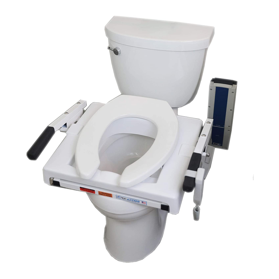
TILT® Toilet Incline Lift – Battery Powered
UNIVERSAL MOTOR MOUNT (LEFT OR RIGHT SIDE)
2-YEAR WARRANTY on product; 1-YEAR WARRANTY on battery.
Please register at www.ezaccess.com/warranty-satisfaction.
© Homecare Products, Inc. All rights reserved.
All text and images contained in this document are proprietary and may not be shared, modified, distributed,
reproduced, or reused without the express written permission of EZ-ACCESS®, a division of Homecare Products, Inc.
Manufactured in the USA
18591 REV 09-18-18
Advertisement
Table of Contents

Related Manuals for EZ-ACCESS TILT


Summary of Contents for EZ-ACCESS TILT
- Page 1 © Homecare Products, Inc. All rights reserved. All text and images contained in this document are proprietary and may not be shared, modified, distributed, reproduced, or reused without the express written permission of EZ-ACCESS®, a division of Homecare Products, Inc. Manufactured in the USA...
-
Page 2: Table Of Contents
• Please read these instructions entirely before installing or using your new TILT. • After installation, it’s important that you cycle - fully raise and lower - the TILT 3-4 times (without sitting on or adding any weight to the seat) to become familiar with its functionality. -
Page 3: Symbols And Warnings
Remove loose rugs and make sure that the area around the TILT is free of all obstructions and moisture. The TILT is strictly an assist lift. The patient must have dexterity, strength, and balance in order to use the TILT safely. -
Page 4: Notes, Box Contents, Tools/Hardware Needed, And Hardware Contents
Before installation, ensure that there is enough space for proper TILT operation. The TILT warranty is not transferable. Attempting to tamper with or modify any portion of the TILT will void the warranty. Using the TILT for anything other than its intended purpose will void the warranty. -
Page 5: Product Overview
PLASTIC SHIELD – REMOVABLE TOILET SEAT – STANDARD SEAT SHOWN HANDLES WITH FOAM GRIP ACTUATOR (MOTOR) – MOUNTED TO TILT FRAME HANDHELD CONTROL – PUSH BUTTON DEVICE DC CONTROL BOX – ATTACHES TO MOUNTING BRACKET BATTERY – ATTACHES TO MOUNTING BRACKET... -
Page 6: Section 1: Pre-Installation
Always use the toilet seat provided with the TILT; do not replace it with any other seat. 2.2 Set the TILT frame on the toilet, in place of the seat that was previously removed. Align two holes on the TILT’s mounting plate with the existing two holes on the toilet bowl. -
Page 7: Section 3: Actuator Mount
FIG. 4 3.2 The actuator mount is universal for both the left and right side of the TILT and is factory packaged configured for a left side mount. Depending on space requirements (see ‘SECTION 1’) or bathroom configuration, it may be necessary to change to a right side mount. - Page 8 For a left side mount, red dots will be facing outward, away from the bowl (FIG. 8). For a right side mount, green dots will be facing outward (FIG. 9). LEFT SIDE MOUNT FRONT, INSTALLING VIEW REVERSE VIEW FIG. 8 RIGHT SIDE MOUNT FRONT, INSTALLING VIEW REVERSE VIEW...
- Page 9 3.7 Place actuator mount over bolt as shown in FIG. 10. ③ ④ 3.8 With your hand on position , push actuator mount down and guide actuator mount tab into the ⑤ ⑥ frame bracket , until it rests completely inside the frame bracket ②...
-
Page 10: Section 4: Actuator Detail And Assembly
4. ACTUATOR DETAIL AND ASSEMBLY 4.1 Using the blue dots on actuator bracket and actuator as guides (FIG. 14), hold actuator ③ ④ ① lower the seat to align the actuator slot with the actuator bracket ② 4.2 Ensure the actuator bracket rests inside of the actuator slot. 4.3 Once aligned, fully insert the pin into actuator and through the bracket (FIG. -
Page 11: Section 5: Installing Mounting Bracket And Control Box
5. INSTALLING MOUNTING BRACKET AND CONTROL BOX 5.1 The battery and control box ship from the factory attached to the mounting bracket and both will need to be removed prior to installing the mounting bracket. 5.1.1 For component understanding, FIG. 16 illustrates the exploded view of the battery, control box, and mounting bracket assembly. -
Page 12: Section 6: Battery
6. BATTERY 6.1 The battery powered TILT operates on a single 24 VDC, 2.9 Ah battery with a separate battery charger (FIG. 21). The battery charger operates off typical household power - 120 VAC at .5 amps - and must be plugged into a properly grounded GFCI protected outlet. -
Page 13: Section 8: Connect Actuator To Control Box
(FIG. 24). 9.3 Test cycle (raise and lower) the TILT 3-4 times, without sitting on the seat, to learn its functionality. 9.4 To RAISE: Push and hold the “up” button to raise the TILT. -
Page 14: Section 10: Post-Installation And Before Use Inspection
It is important that an effective cleaning and sanitization schedule be established that fits your situation. You may clean debris and soils from the TILT using a soft cloth with warm water and mild soap, noting that while soap and water may remove debris, additional methods are needed to sanitize the TILT. -
Page 15: Section 12: Troubleshooting
12. TROUBLESHOOTING SYMPTOM POTENTIAL CAUSE SOLUTION TILT will not • Battery discharged • Charge battery lift • Battery damaged, cannot hold charge • Replace battery and charge • Battery charger not charging • Call for assistance checking battery and charger •...
Need help?
Do you have a question about the TILT and is the answer not in the manual?
Questions and answers